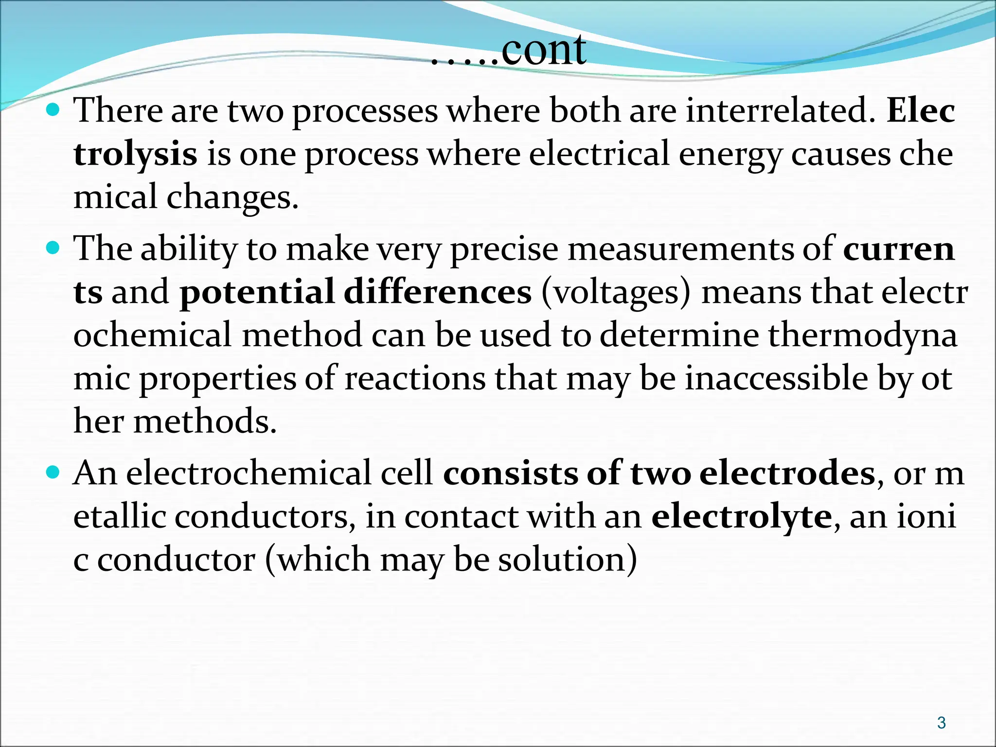
The document discusses electrochemical cells, focusing on electrochemistry as the study of energy transformations between electrical and chemical forms. It explains processes like electrolysis, galvanic cells, and the reactions occurring at electrodes, providing insight into their applications and principles. The document also addresses the thermodynamics of these cells, including cell potentials, Nernst equation, and the role of faraday in quantifying electric charge.


![Reversible electrodes
Electrode type Example Description Electrode reaction (in reduction
direction)
Metal metal-ion
electrode
Cu(s)│Cu2+(aq) Metal bathed in electrolyte
containing its own ions.
Cu2+(aq)+2e→Cu(s)
Ion – ion (redox)
electrode
Pt(s)│Fe3+,Fe2+(aq)
Pt|[Fe(CN)6]3–
,[Fe(CN)6]4–
Noble metal in contact with
solution of a redox couple
Fe3+(aq)+e→Fe2+(aq)
[Fe(CN)6]3– + e→[Fe(CN)6]4–
Metal insoluble salt
electrode
Hg(s) │Hg2Cl2(s)
│KCl(aq)
Ag|AgCl(s) |Cl–
Metal in contact with its
insoluble salt (i.s.) and a solution
containing a soluble anion of the
i.s.
Hg2Cl2(s)+2e→2Hg+2Cl-
AgCl(s) + e → Ag(s) + Cl–
Gas electrode Pt(s)│H2(g) │H+(aq) Noble metal in contact with a
saturated solution for a gas and
contains the reduced or oxidized
form of the gas
H+(aq)+e→1/2H2(g)
Amalgam and
membrane
Na(Hg) solution of a metal in liquid
mercury
28](https://image.slidesharecdn.com/newelectrochemistryedi-1-240307123528-6d8ddb53/75/new-Electrochennnnnnnnnnnnnnnmistry-edi-1-ppt-28-2048.jpg)


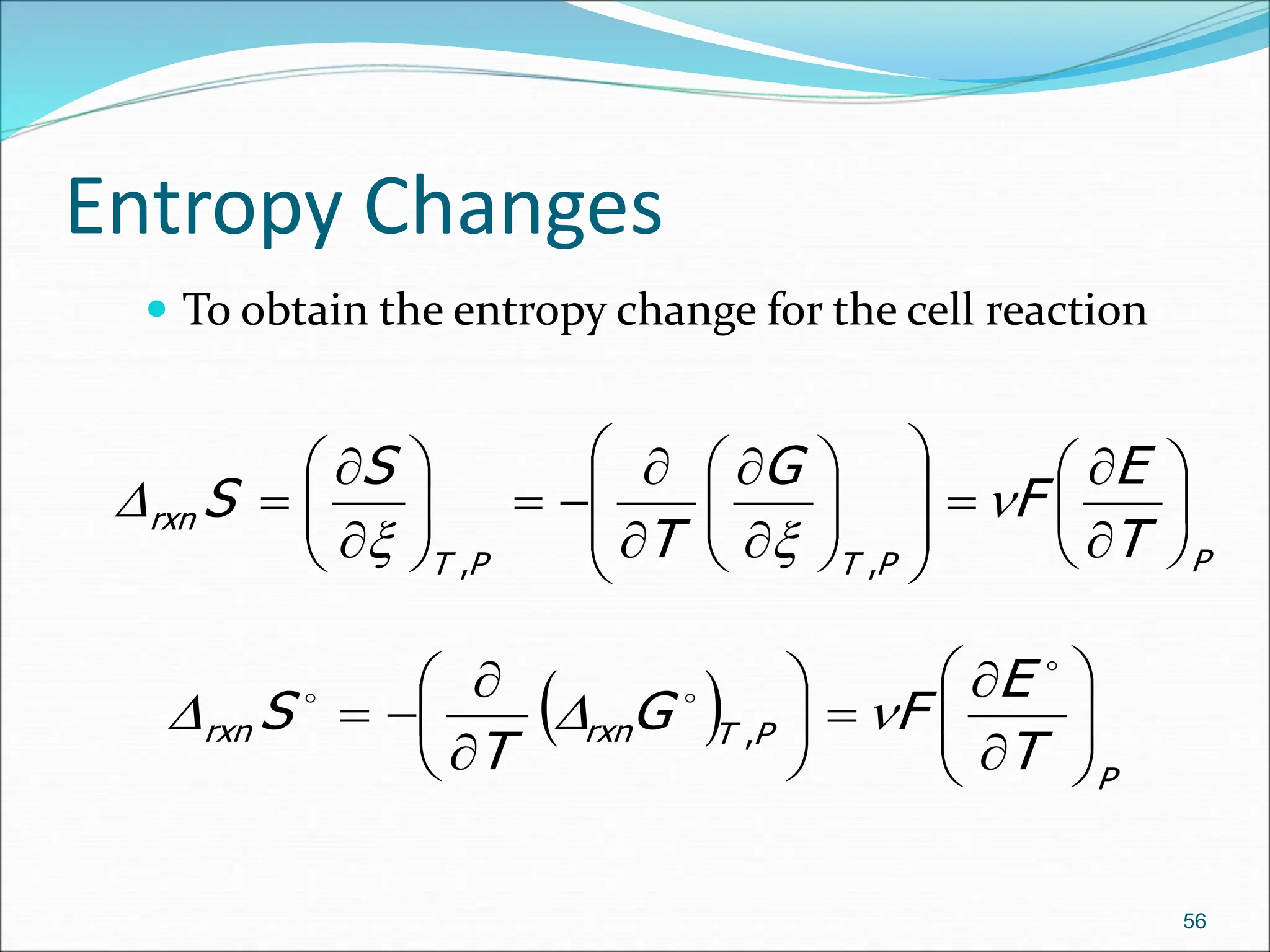

![E.g
The Weston Cadmium Cell has an e.m.f. (E) of 1.01463 V at 298
K and a temperature coefficient of -5.00 × 10⁻⁵ V K–
1.calculate the thermodynamic quantities of the overall cell
reaction.
ΔG = – n F E = – 2 × 96500 C mol–1 × 1.01463 V
= –195824 Jmol-1
ΔS = nF[ ∂ E/∂T]p
= 2 (96500 C mol–1) × (– 5.00 × 10⁻⁵) V K–1
= – 9.65 Jmol-1 K–1
ΔH = ΔG + T ΔS
= – 195824 Jmol-1 + 298 K (– 9.65 Jmol-1 K–1)
= -198700 Jmol-1
58](https://image.slidesharecdn.com/newelectrochemistryedi-1-240307123528-6d8ddb53/75/new-Electrochennnnnnnnnnnnnnnmistry-edi-1-ppt-58-2048.jpg)