COMPUTER NETWORKS -19CS3602
• MODULE 3 8 Hrs
• Network Layer: Network Layer Design issues, store and forward packet switching
• connection less and connection oriented networks-routing algorithms-optimality principle,
• shortest path, flooding, Distance Vector Routing, Control to Infinity Problem, Hierarchical
• Routing, Congestion control algorithms, admission control, Classful IP addresses(A,B,C,D)
• ,QoS, Details of IP Packet
3.
Design issues inNetwork
Layer
DAYANANDA SAGAR UNIVERSITY , DEPARTMENT OF CSE
COMPUTER NETWORKS - 19CS3602
4.
Introduction
• The NetworkLayer is responsible for getting packets from the source to the
destination.
• To do so, the network layer must know about the topology of the network.
• It also chooses the appropriate path in networks.
• It must also take consider the situation of overloading or underloading the
communication lines while choosing the routes across the networks.
COMPUTER NETWORKS - 19CS3602
DAYANANDA SAGAR UNIVERSITY , DEPARTMENT OF CSE
5.
COMPUTER NETWORKS -19CS3602
Store-and-Forward Packet Switching
DAYANANDA SAGAR UNIVERSITY , DEPARTMENT OF CSE
6.
COMPUTER NETWORKS -19CS3602
Store-and-Forward Packet Switching
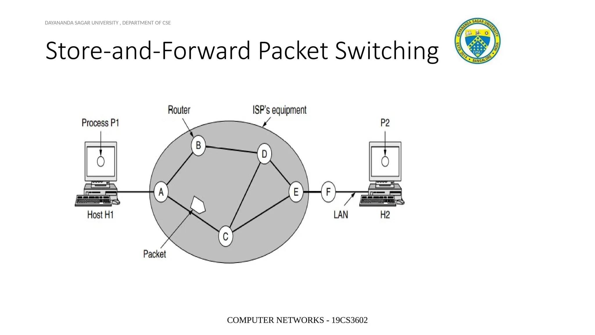
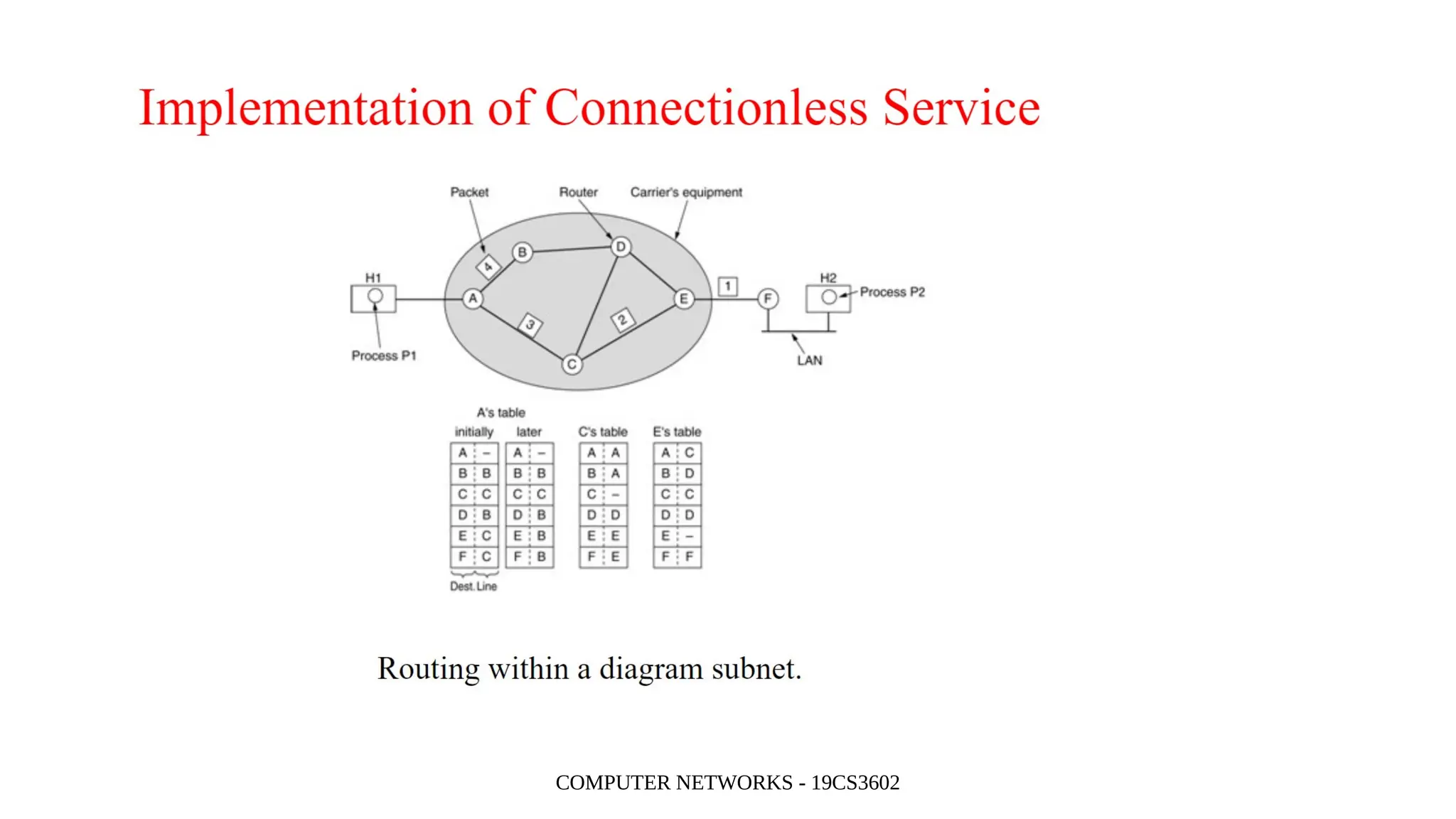
• Consider the following network, having two hosts Host H1, and Host H2.
• The major components of the network are the routers and ISP (Internet Service
Providers) equipment.
• H1 is directly connected to the ISP equipment where as H2 uses a router F which
is outside the network.
DAYANANDA SAGAR UNIVERSITY , DEPARTMENT OF CSE
7.
COMPUTER NETWORKS -19CS3602
Store-and-Forward Packet Switching
• The host transmits the packet to the nearest router.
• The packet is stored there until it has fully arrived and the link has finished its
processing by verifying the checksum.
• Then it is forwarded to the next router along the path until it reaches the
destination.
• This mechanism is called store-and-forward packet switching.
DAYANANDA SAGAR UNIVERSITY , DEPARTMENT OF CSE
8.
COMPUTER NETWORKS -19CS3602
Services provided to Transport Layer
• The services should be independent of the router.
• The transport layer should be shielded from the number, type and topology of
the routers.
• The network address must be same across LANs and WANs.
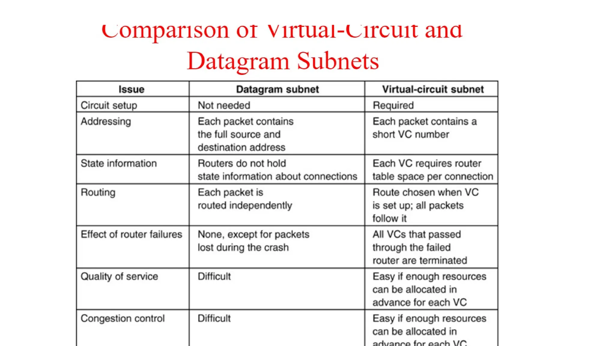
• The main design issues is on whether the network layer should provide
connection-oriented service or connectionless service.
DAYANANDA SAGAR UNIVERSITY , DEPARTMENT OF CSE
COMPUTER NETWORKS -19CS3602
ATM
• Asynchronous Transfer Mode (ATM) is a cell-switching, connection-oriented
technology. In ATM networks, end stations attach to the network using dedicated
full duplex connections. The ATM networks are constructed using switches, and
switches are interconnected using dedicated physical connections.
• A virtual circuit (VC) is a means of transporting data over a packet-switched
network in such a way that it appears as though there is a dedicated physical link
between the source and destination end systems of this data. The term virtual
circuit is synonymous with virtual connection.
13.
Department of ComputerScience & Engineering 13
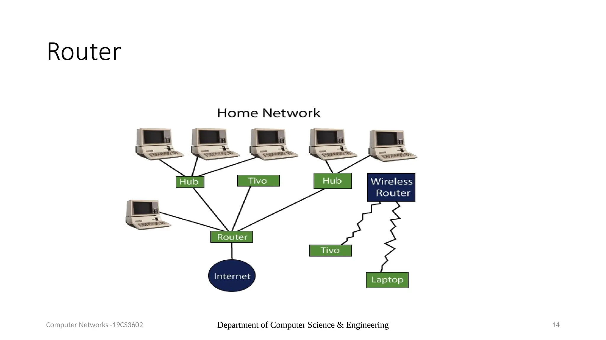
What is a router?
• A router is a switching device for networks, which is able to route network
packets, based on their addresses, to other networks or devices.
• Among other things, they are used for Internet access, for coupling networks or
for connecting branch offices to a central office via VPN (Virtual Private Network)
• In the OSI layer model, the switching of data packets through the router is based
on the address on the network layer (layer 3).
Computer Networks -19CS3602
Department of ComputerScience & Engineering 15
How a router functions?
• A router has multiple interfaces and receives data packets through
them. It evaluates the network addresses of the incoming packets and
decides which interface to forward the packet to.
• It uses its local routing table for decision-making. This can be
statically configured or calculated via dynamic routing protocols such
as OSPF or BGP.
Computer Networks -19CS3602
16.
Department of ComputerScience & Engineering 16
Various types of routers
• Backbone routers are high-performance routers of the carrier class,
which route and forward packets with rapid speeds of several gigabits
per second. They are housed in data centres.
• For interfacing with networks of other providers, Internet service
providers may use border routers or edge routers, which mainly use
the routing protocol BGP.
• For connecting to the Internet, access routers are used, which allow
devices in a local area network to access Internet via DSL, cable,
wireless or ISDN.
Computer Networks -19CS3602
17.
Department of ComputerScience & Engineering 17
Routers and telephony
• Many Internet routers have additional functions for telephony. They
often have full telephone systems integrated within the devices.
• While a normal Internet connection provides sufficient access for VoIP
telephony, routers with telephone systems for standard telephony
need interfaces for access to the analogue or digital (ISDN) telephone
network.
Computer Networks -19CS3602
ISDN or Integrated Services Digital Network is a circuit-switched telephone network system
that transmits both data and voice over a digital line. You can also think of it as a set of
communication standards to transmit data, voice, and signaling. These digital lines could be
copper lines
18.
5.2 Routing Algorithms
•The main function of NL (Network Layer) is routing packets
from the source machine to the destination machine.
• The algorithms that choose the routes and the data
structures that they use are a major area of network layer
design.
• The routing algorithm is that part of the NL software
responsible for deciding which output line an incoming
packet should be transmitted on.
19.
5.2 Routing Algorithms
•There are two processes inside router:
a) One of them handles each packet as it arrives,
looking up the outgoing line to use for it in the
routing table. This process is forwarding.
b) The other process is responsible for filling in and
updating the routing tables. That is where the
routing algorithm comes into play. This process is
routing.
20.
5.2 Routing Algorithms
•Regardless of whether routes are chosen
independently for each packet or only
when new connections are established,
certain properties are desirable in a
routing algorithm:
• correctness, simplicity,
• robustness, stability,
• fairness, and optimality.
21.
5.2 Routing Algorithms
•Correctness and simplicity hardly require
comment.
• Robustness: the routing algorith should be able to
cope with changes in topology and traffic without
requiring all jobs in all hosts to be aborted and the
network to be rebooted every time some router
crashes.
22.
5.2 Routing Algorithms
•Stability is also an important goal for the
routing algorithm. A stable algorithm
reaches equilibrium and stays there.
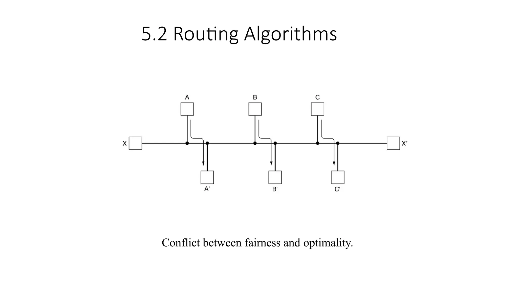
• Fairness and optimality may sound
obvious – surely no reasonable person
would oppose them – but as it turn out, they
are often contradictory goals.
5.2 Routing Algorithms
•Routing algorithms can be grouped into two major
classes: nonadaptive and adaptive.
• Nonadaptive algorithm do not base their routing decisions
on measurements or estimates of the current traffic and
topology. Instead, the choice of the route to use to get
from I to J is computed in advance, off line, and
downloaded to the routers when the network is booted.
This procedure is sometimes called static routing.
25.
5.2 Routing Algorithms
•Adaptivealgorithm, in contrast, change their routing decisions to
reflect changes in the topology, and usually the traffic as well.
•Adaptive algorithms differ in where they get their information
(e.g., locally, from adjacent routers, or from all routers), when
they change the routes (e.g., every ∆T sec, when the load changes
or when the topology changes), and what metric is used for
optimization (e.g., distance, number of hops, or estimated transit
time). This procedure is called dynamic routing.
5.2 Routing Algorithms-- The
Optimality Principle (1)
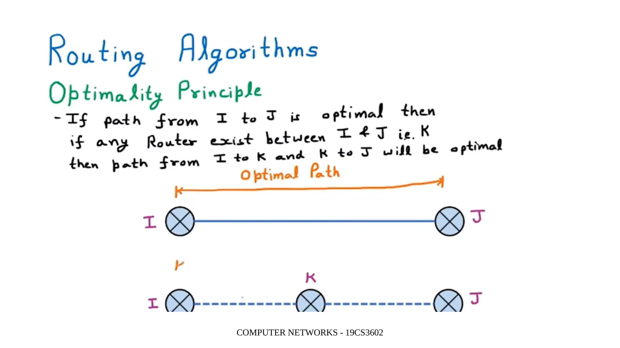
•One can make a general statement about optimal
routes without regard to network topology or traffic.
•This statement is known as the optimality principle.
•It states that if router J is on the optimal path from router
I to router K, then the optimal path from J to K also falls
along the same route.
28.
5.2 Routing Algorithms----The
Optimality Principle (2)
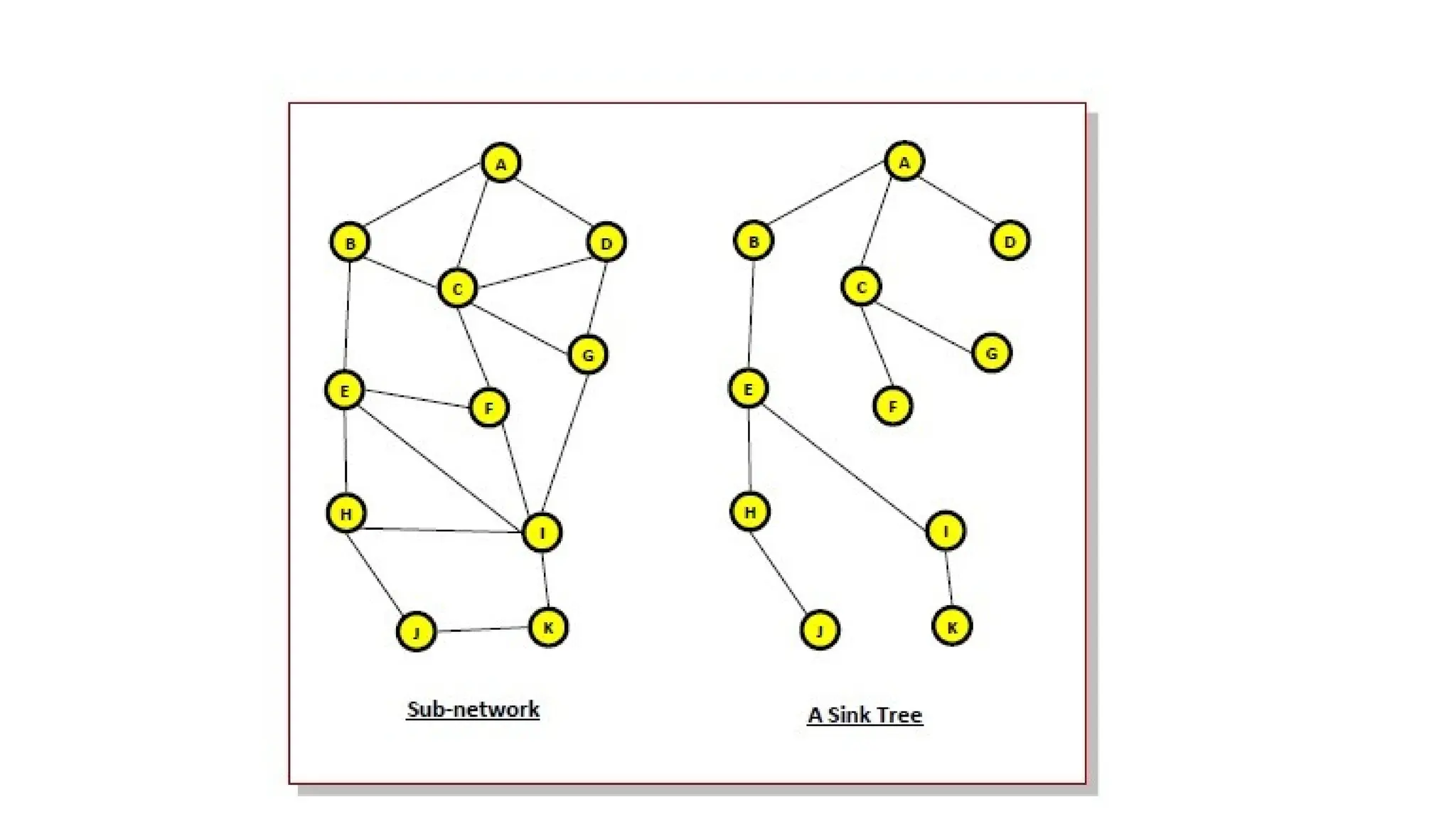
•As a direct consequence of the optimality principle,
we can see that the set of optimal routes from all
sources to a given destination form a tree rooted at
the destination.
•Such a tree is called a sink tree.
•The goal of all routing algorithms is to discover and
use the sink trees for all routers
29.
• A sinktree may not be unique.
• There can exist more than one sink trees having same path length.
The objective of routing algorithms is to find the sink trees for all
nodes in the network.
• Since, links and nodes may go down and revive during data
transmission, the alternative sink trees and the paths are also made
available to the nodes.
• Being a tree, a sink tree does not contain any loops or cycles. So
each packet can be delivered within a finite number of hops. Also, a
packet will not be infinitely rotated within a subnet.
30.
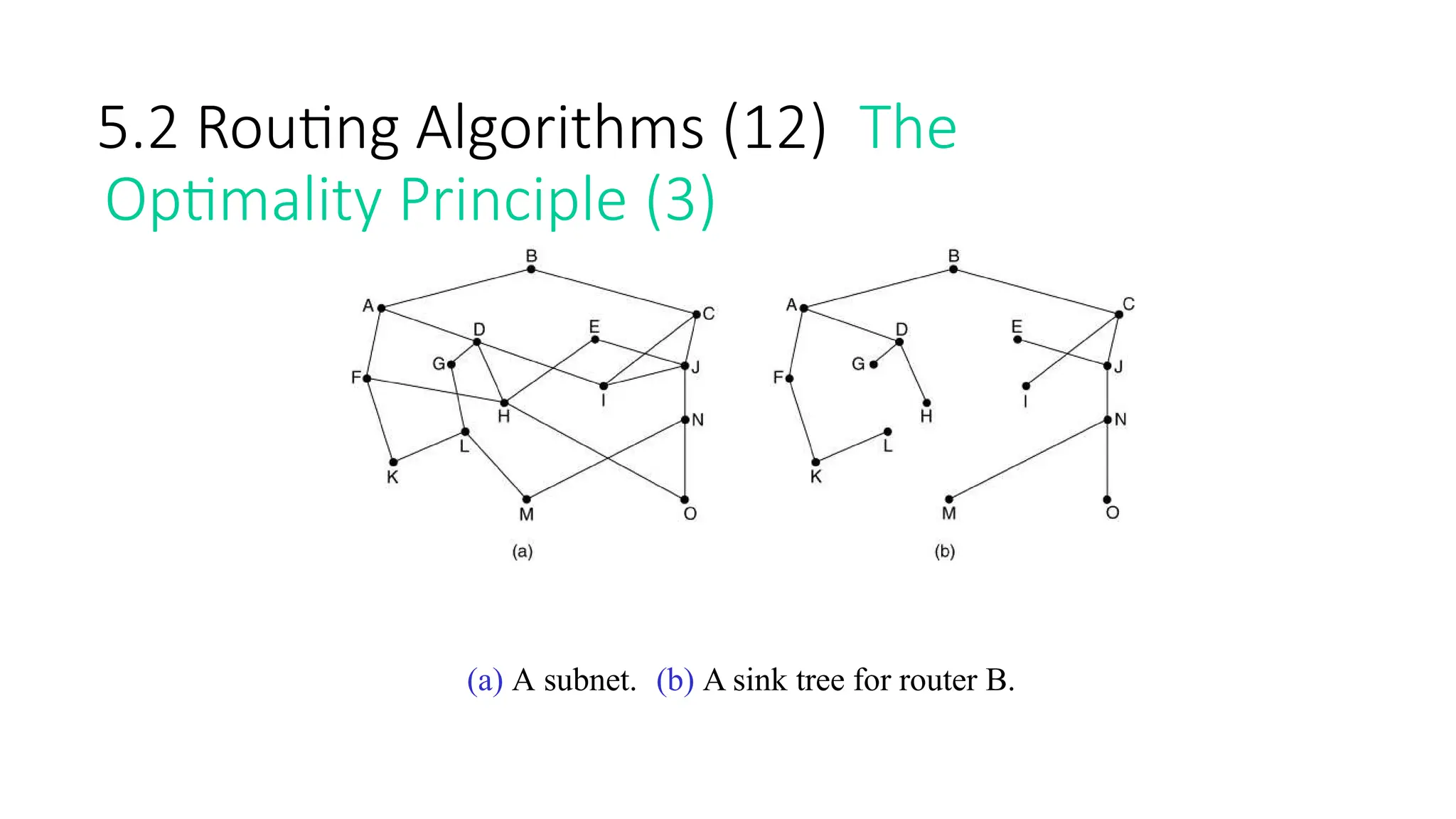
5.2 Routing Algorithms(12) The
Optimality Principle (3)
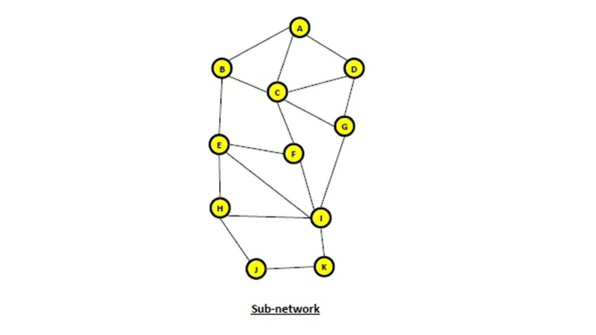
(a) A subnet. (b) A sink tree for router B.
5.2 Routing Algorithms(13)
Shortest Path Routing (1)
•The idea is to build a graph of the subnet, with each
node of the graph representing a router and each arc
of the graph representing a communication line or
link.
•To choose a route between a given pair of routers,
the algorithm just finds the shortest path between
them on the graph.
35.
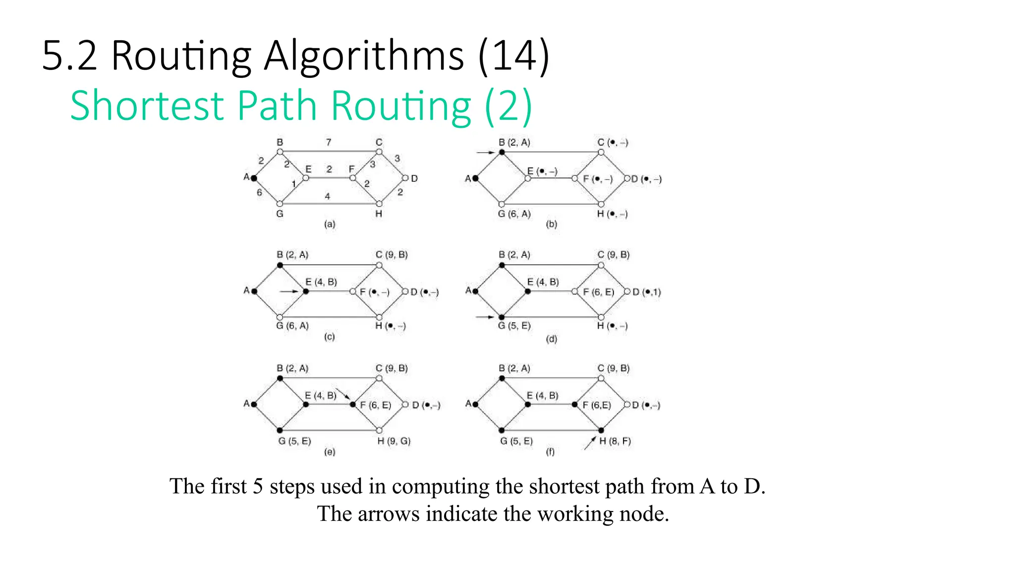
5.2 Routing Algorithms(14)
Shortest Path Routing (2)
The first 5 steps used in computing the shortest path from A to D.
The arrows indicate the working node.
36.
5.2 Routing AlgorithmsShortest Path Routing
•Many other metrics besides hops and physical distance
are also possible.
•For example, each arc could be labeled with the mean queuing
and transmission delay for some standard test packet as
determined by hourly test runs.
•With this graph labeling, the shortest path is the fastest path
rather than the path with the fewest arcs or kilometers.
37.
5.2 Routing Algorithms- Shortest Path Routing
•In the general case, the labels on the arcs could be computed as
a function of the distance, bandwidth, average traffic,
communication cost, mean queue length, measured delay, and
other factors.
•By changing the weighting function, the algorithm would then
compute the “shortest” path measured according to any one of a
number of criteria or to a combination of criteria.
38.
What is flooding?
•In a computer network, flooding occurs
• when a router uses a nonadaptive routing algorithm to
send an incoming packet to every outgoing link except the
node on which the packet arrived.
• Flooding is a way to distribute routing protocols updates quickly
to every node in a large network.
39.
5.2 Routing Algorithms
Flooding
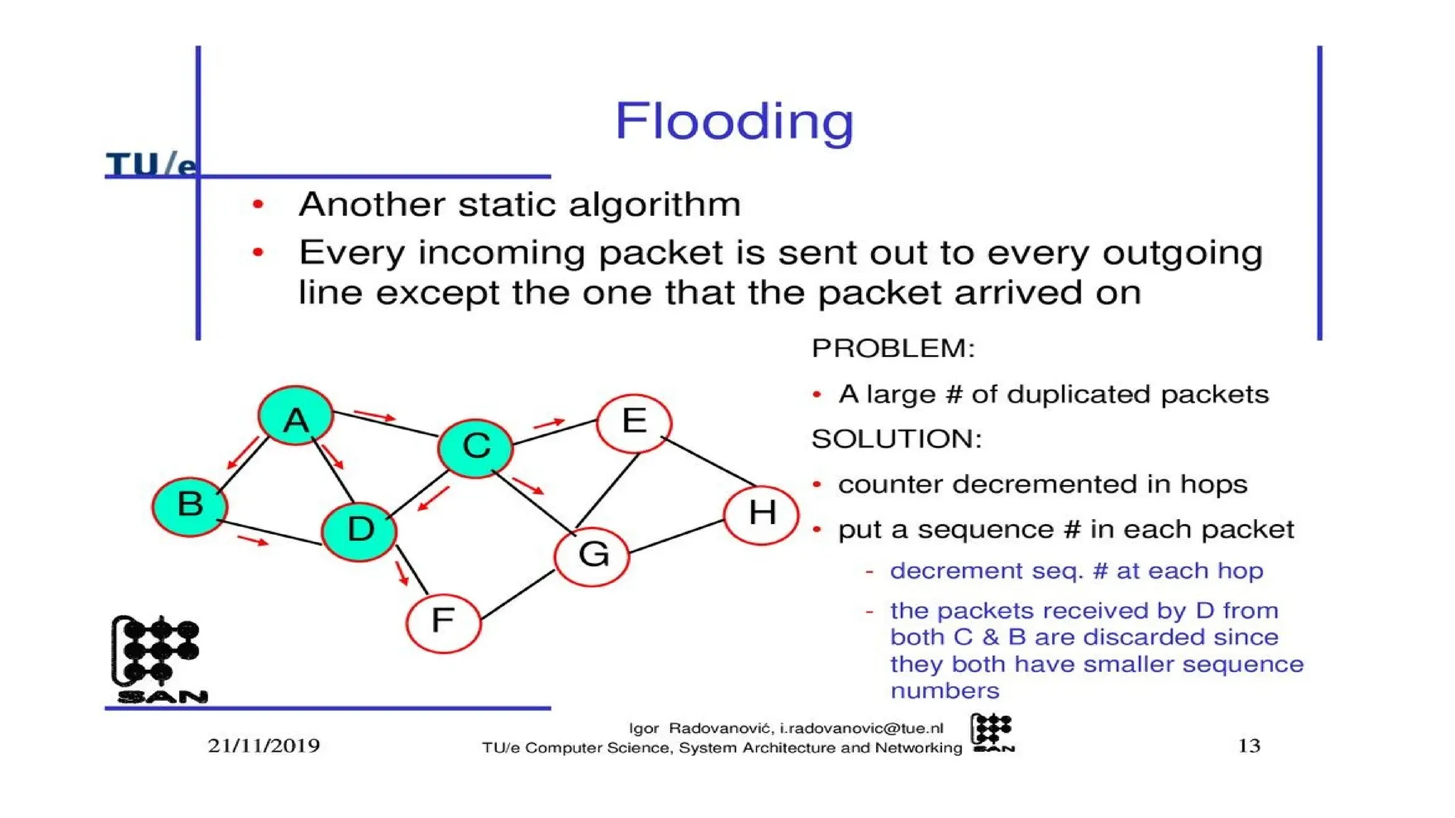
•Another static algorithm is flooding, in which every
incoming packet is sent out on every outgoing line except
the one it arrived on.
• Flooding obviously generates vast numbers of duplicate
packets, in fact, an infinite number unless some measures
are taken to damp the process.
40.
5.2 Routing Algorithms
Flooding
•One such measure is to have a hop counter contained in
the header of each packet, which is decremented at each
hop, with the packet being discarded when the counter
reaches zero.
• Ideally, the hop counter should be initialized to the length
of the path from source to destination.
41.
5.2 Routing Algorithms
Flooding
•A variation of flooding that is slightly more
practical is selective flooding.
• In this algorithm the routers do not send every
incoming packet out on every line, only on those
lines that are going approximately in the right
direction.
• Flooding is not practical in most
applications.
43.
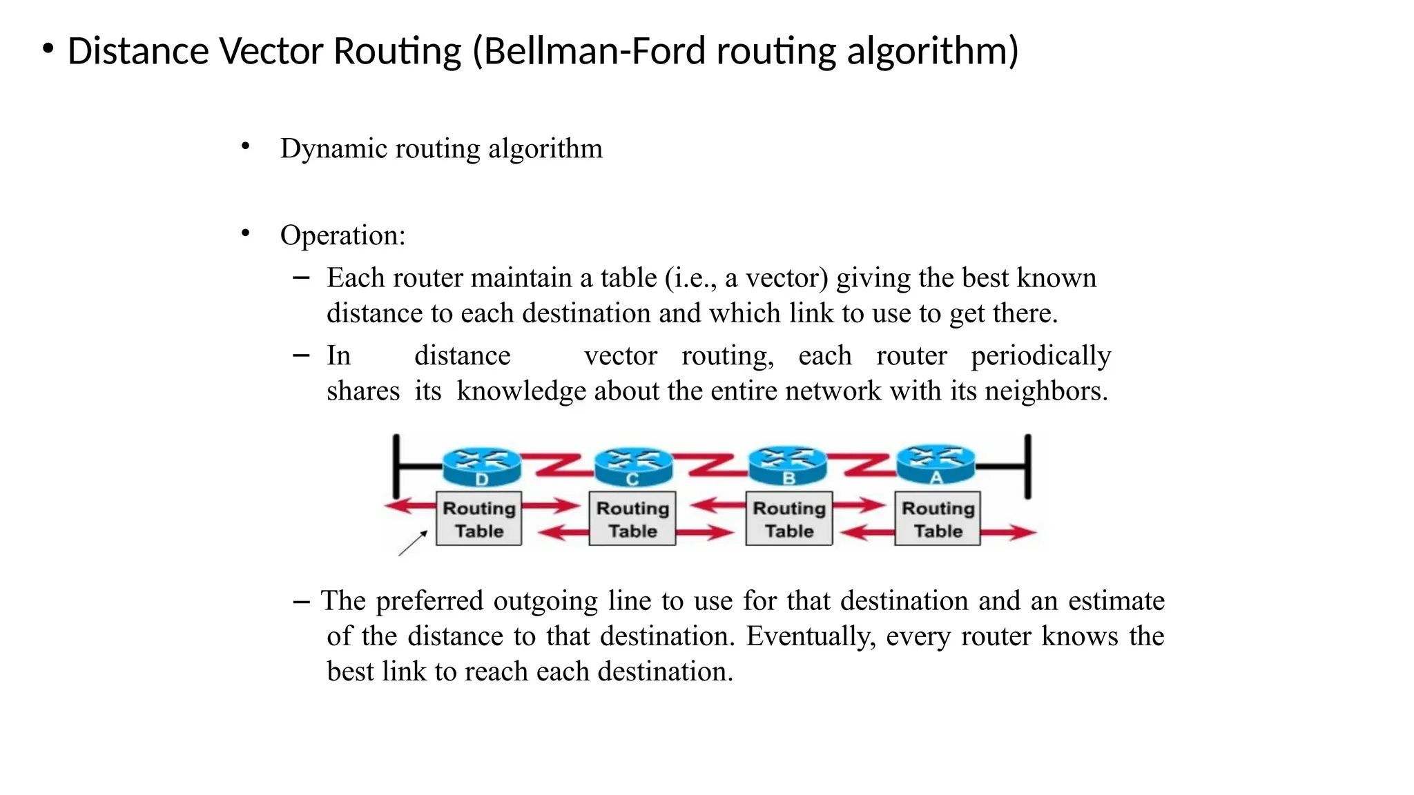
• Distance VectorRouting (Bellman-Ford routing algorithm)
• Dynamic routing algorithm
• Operation:
– Each router maintain a table (i.e., a vector) giving the best known
distance to each destination and which link to use to get there.
– In distance vector routing, each router periodically
shares its knowledge about the entire network with its neighbors.
– The preferred outgoing line to use for that destination and an estimate
of the distance to that destination. Eventually, every router knows the
best link to reach each destination.
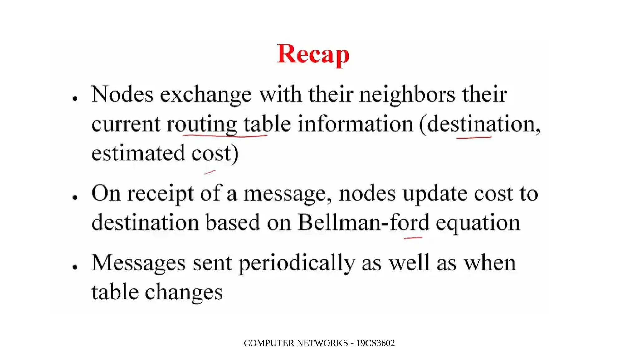
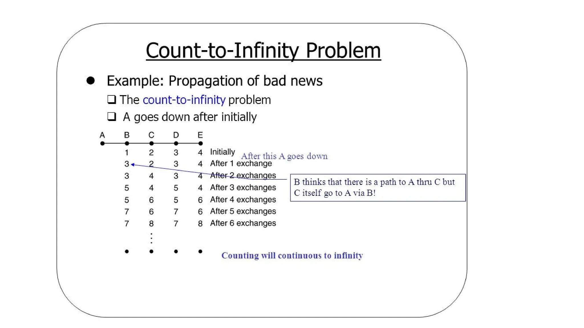
What is TheCount to Infinity problem
• The Count to Infinity problem arises from the routing loop in
this Distance Vector Routing(DVR) network. Such Routing
Loops usually occurs when 2 routers send an update together
at the same time or when an interface goes down
48.
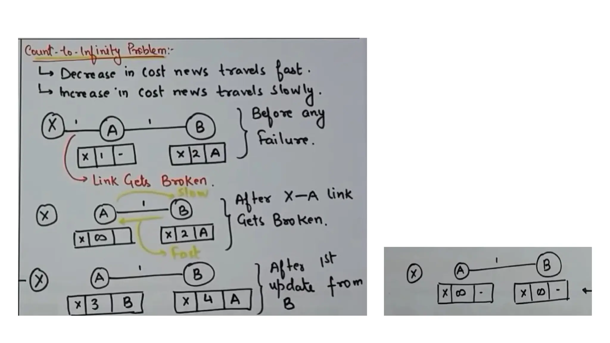
Count to InfinityProblem
• It is an issue in Distance Vector Routing
• Counting to infinity is just another name for a routing loop
• A problem with distance-vector routing is that any decrease in cost
(good news) propagates quickly, but any increase in cost (bad news)
will propagate slowly.
• For a routing protocol to work properly, if a link is broken (cost
becomes infinity), every other router should be aware of it
immediately, but in distance-vector routing, this takes some time. The
problem is referred to as count to infinity.
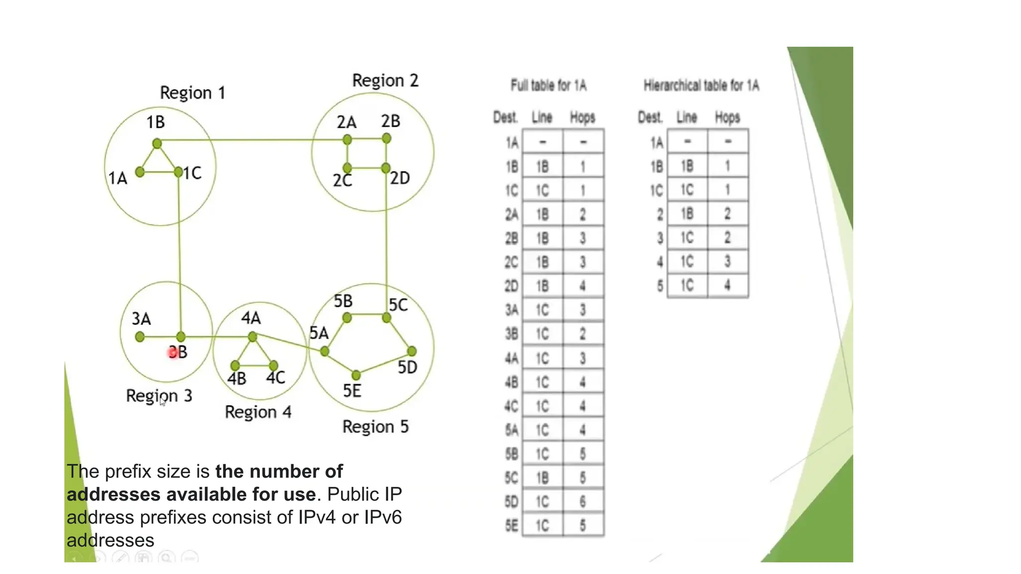
The prefix sizeis the number of
addresses available for use. Public IP
address prefixes consist of IPv4 or IPv6
addresses
56.
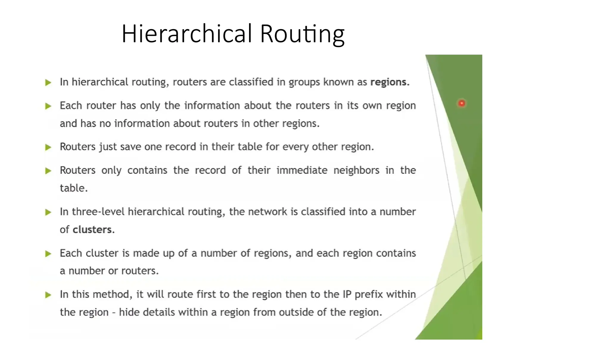
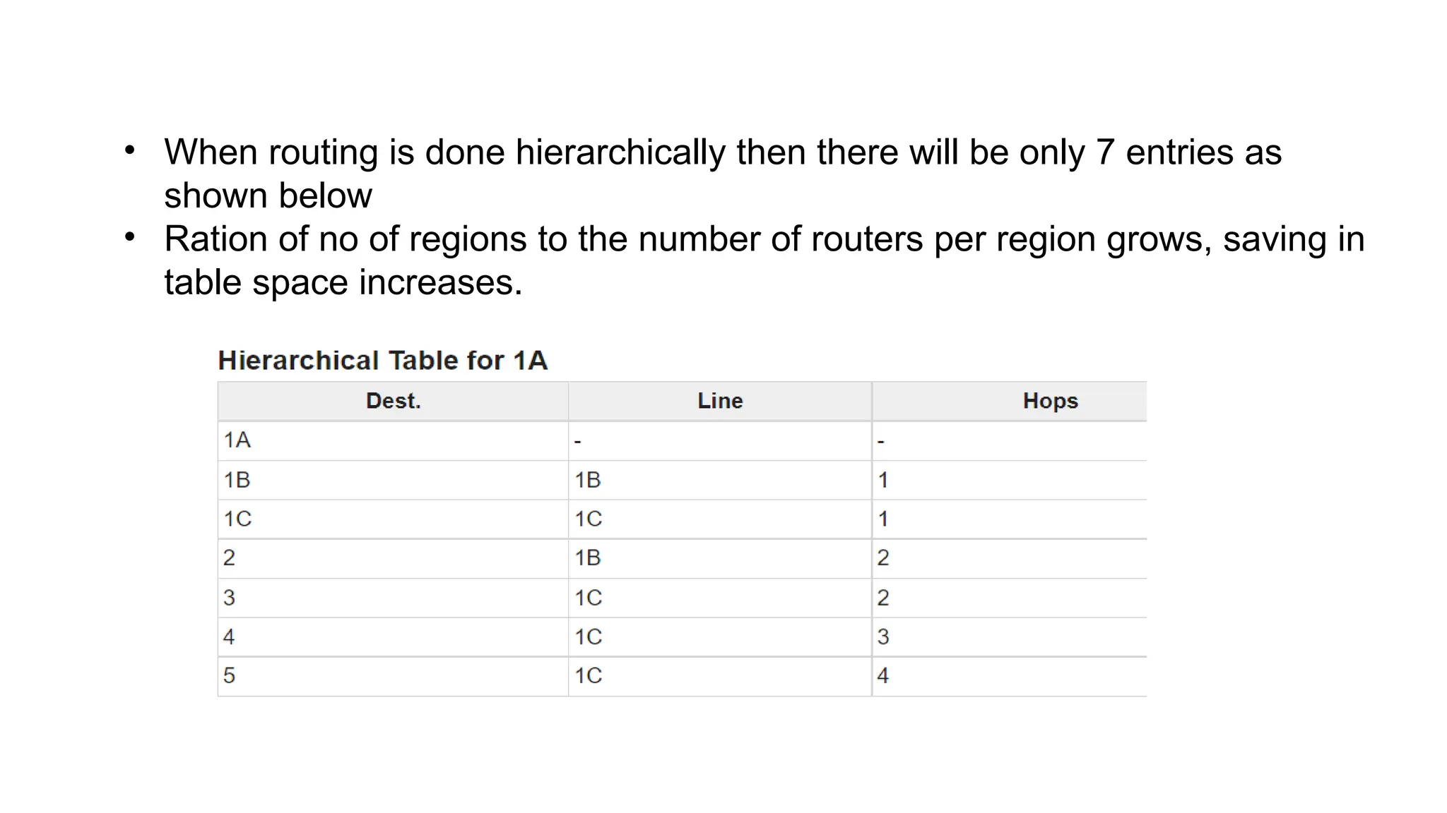
• When routingis done hierarchically then there will be only 7 entries as
shown below
• Ration of no of regions to the number of routers per region grows, saving in
table space increases.
57.
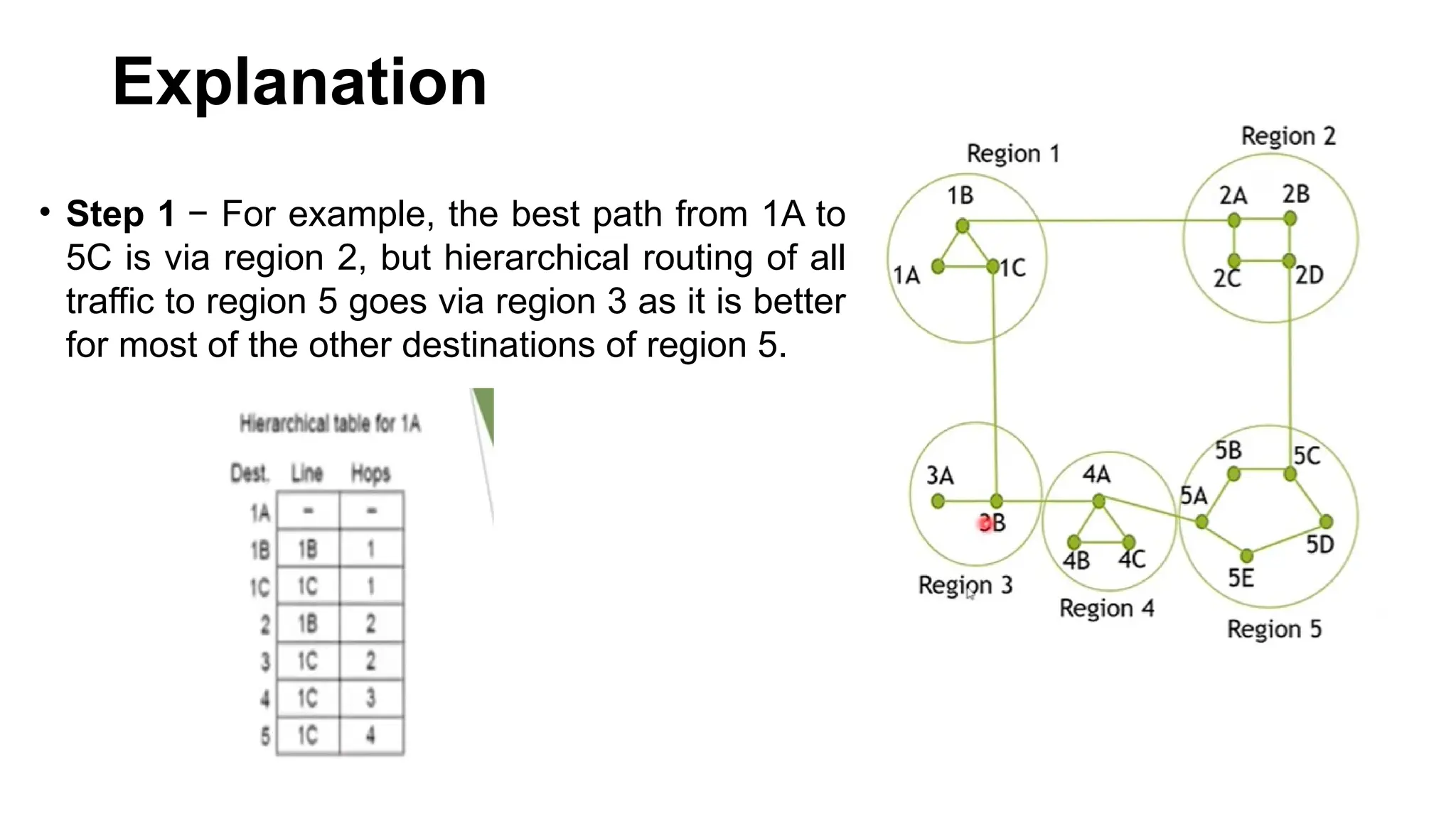
Explanation
• Step 1− For example, the best path from 1A to
5C is via region 2, but hierarchical routing of all
traffic to region 5 goes via region 3 as it is better
for most of the other destinations of region 5.
58.
Think and solve?
Ifthe same subnet of 720 routers is partitioned into 8 clusters,
each containing 9 regions and each region containing 10 routers.
Then what will be the total number of table entries in each router.
59.
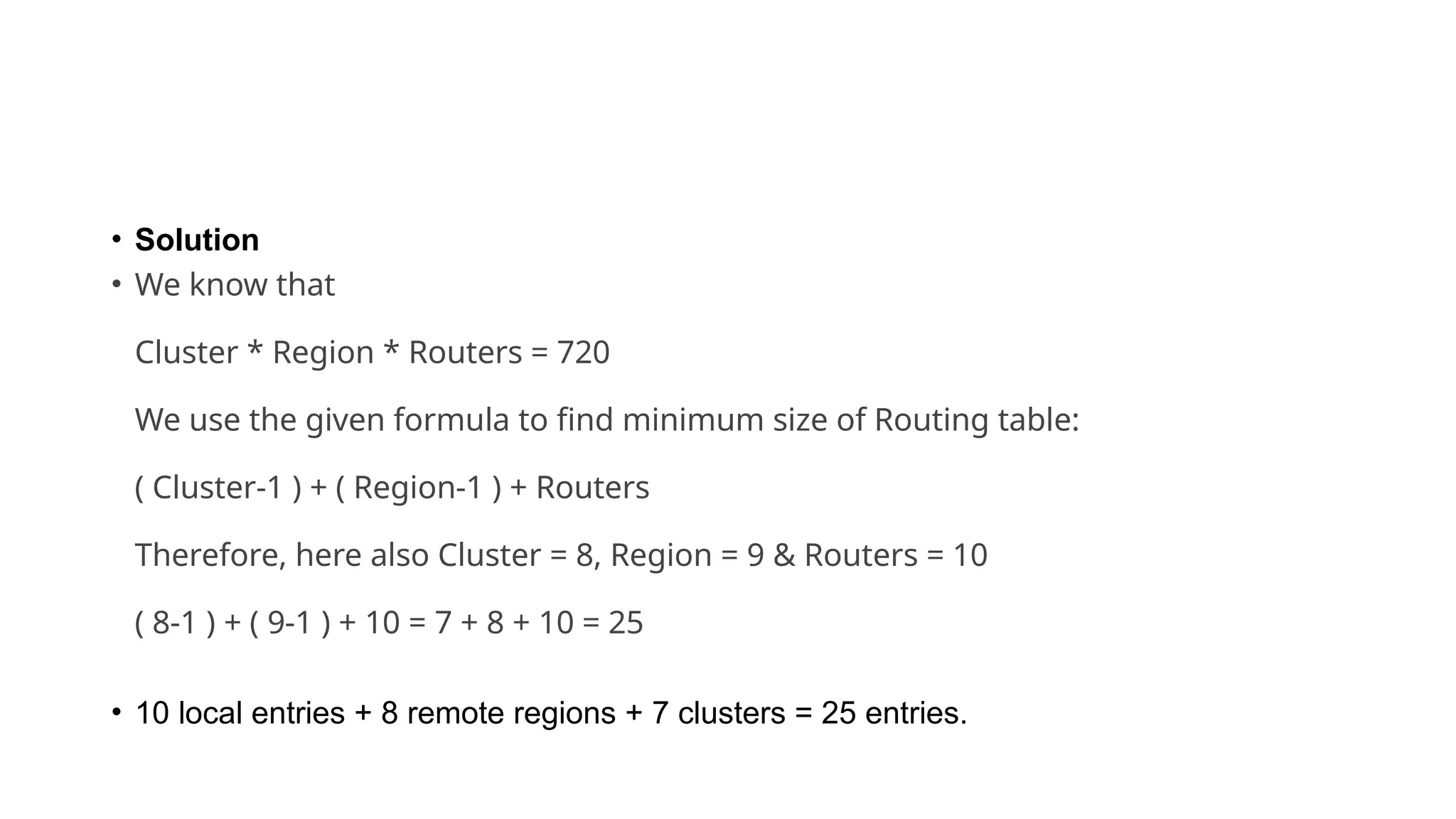
• Solution
• Weknow that
Cluster * Region * Routers = 720
We use the given formula to find minimum size of Routing table:
( Cluster-1 ) + ( Region-1 ) + Routers
Therefore, here also Cluster = 8, Region = 9 & Routers = 10
( 8-1 ) + ( 9-1 ) + 10 = 7 + 8 + 10 = 25
• 10 local entries + 8 remote regions + 7 clusters = 25 entries.
60.
61
5.3. Congestion ControlAlgorithms
• When too many packets are present in (a part of)
the subnet, performance degrades.
• This situation is called congestion.
61.
62
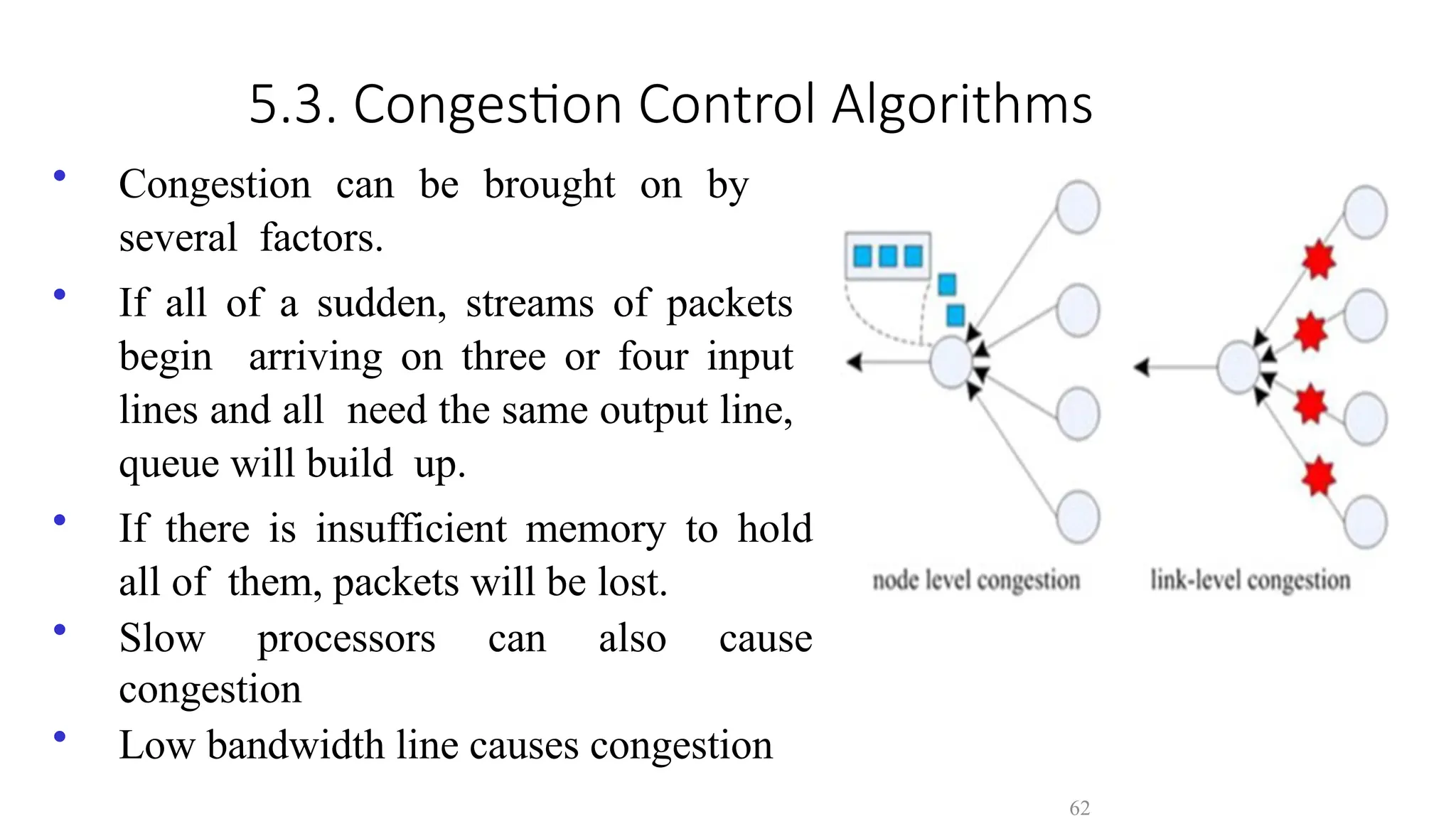
5.3. Congestion ControlAlgorithms
• Congestion can be brought on by
several factors.
• If all of a sudden, streams of packets
begin arriving on three or four input
lines and all need the same output line,
queue will build up.
• If there is insufficient memory to hold
all of them, packets will be lost.
• Slow processors can also cause
congestion
• Low bandwidth line causes congestion
62.
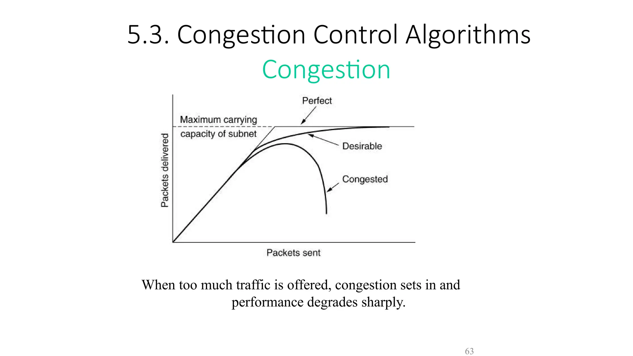
5.3. Congestion ControlAlgorithms
Congestion
When too much traffic is offered, congestion sets in and
performance degrades sharply.
63
63.
64
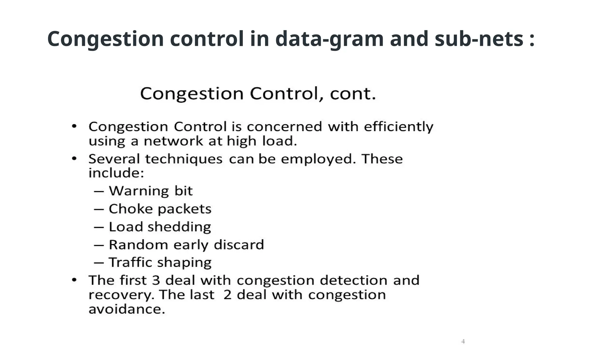
5.3. Congestion ControlAlgorithms
• General Principles of Congestion Control
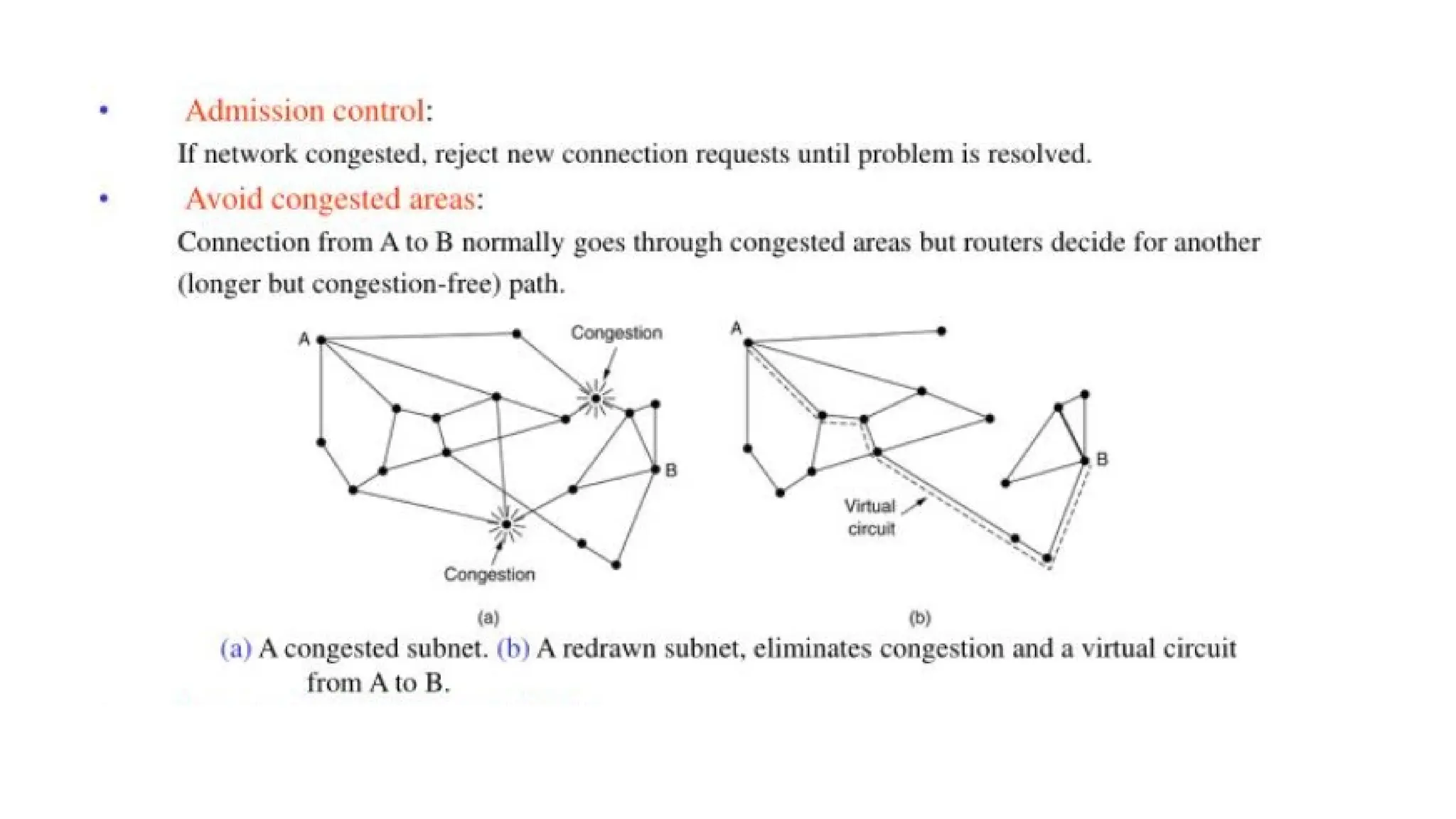
• Congestion Prevention Policies
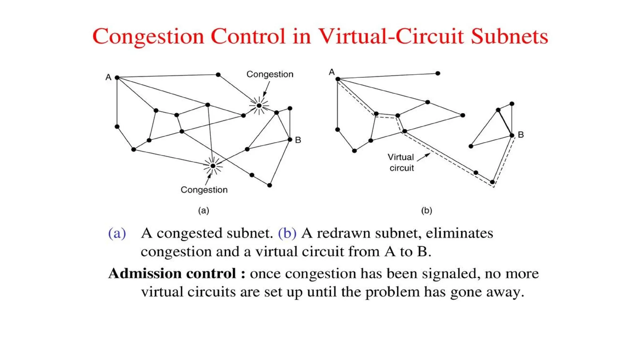
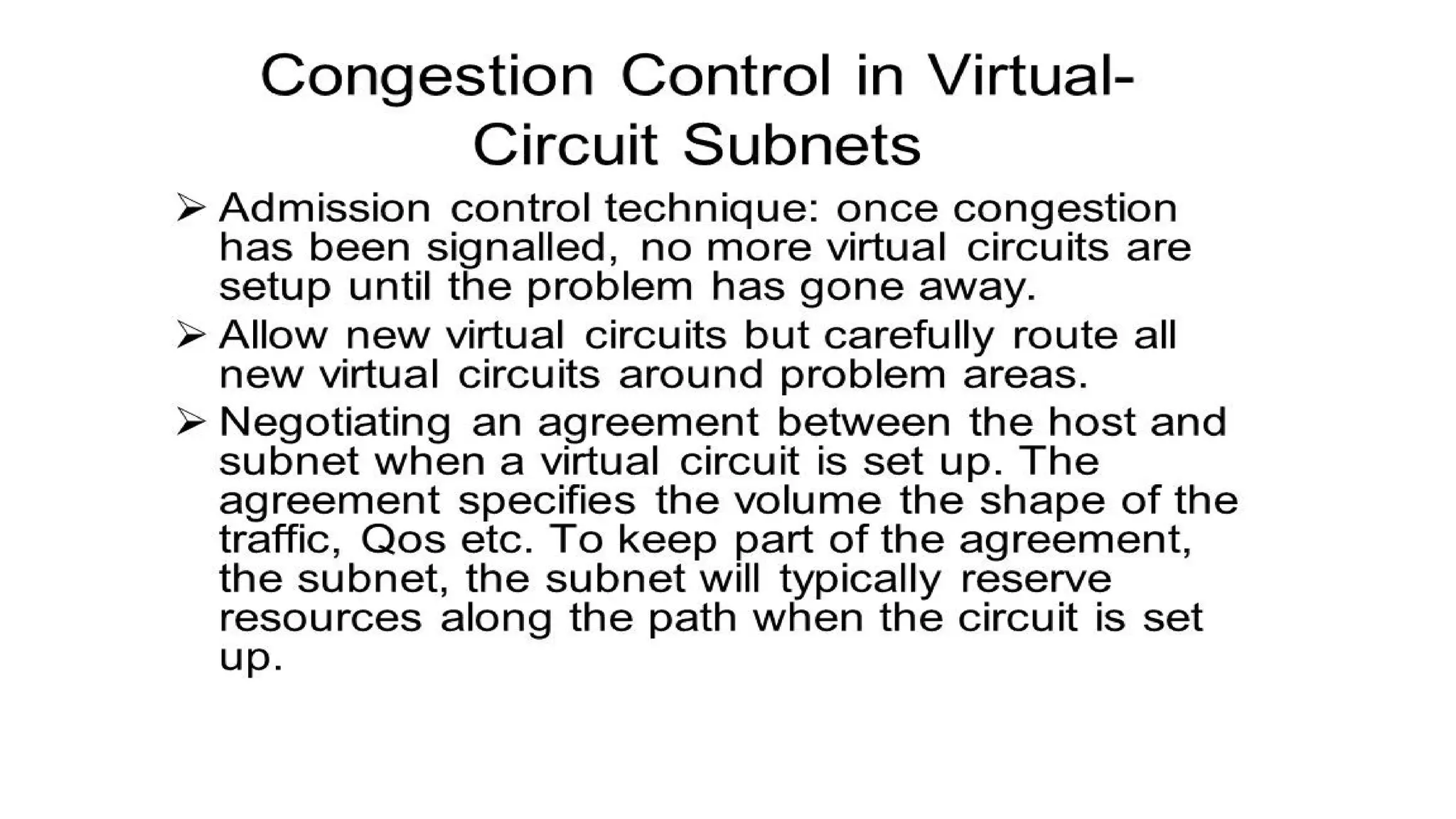
• Congestion Control in Virtual-Circuit Subnets
• Congestion Control in Datagram Subnets
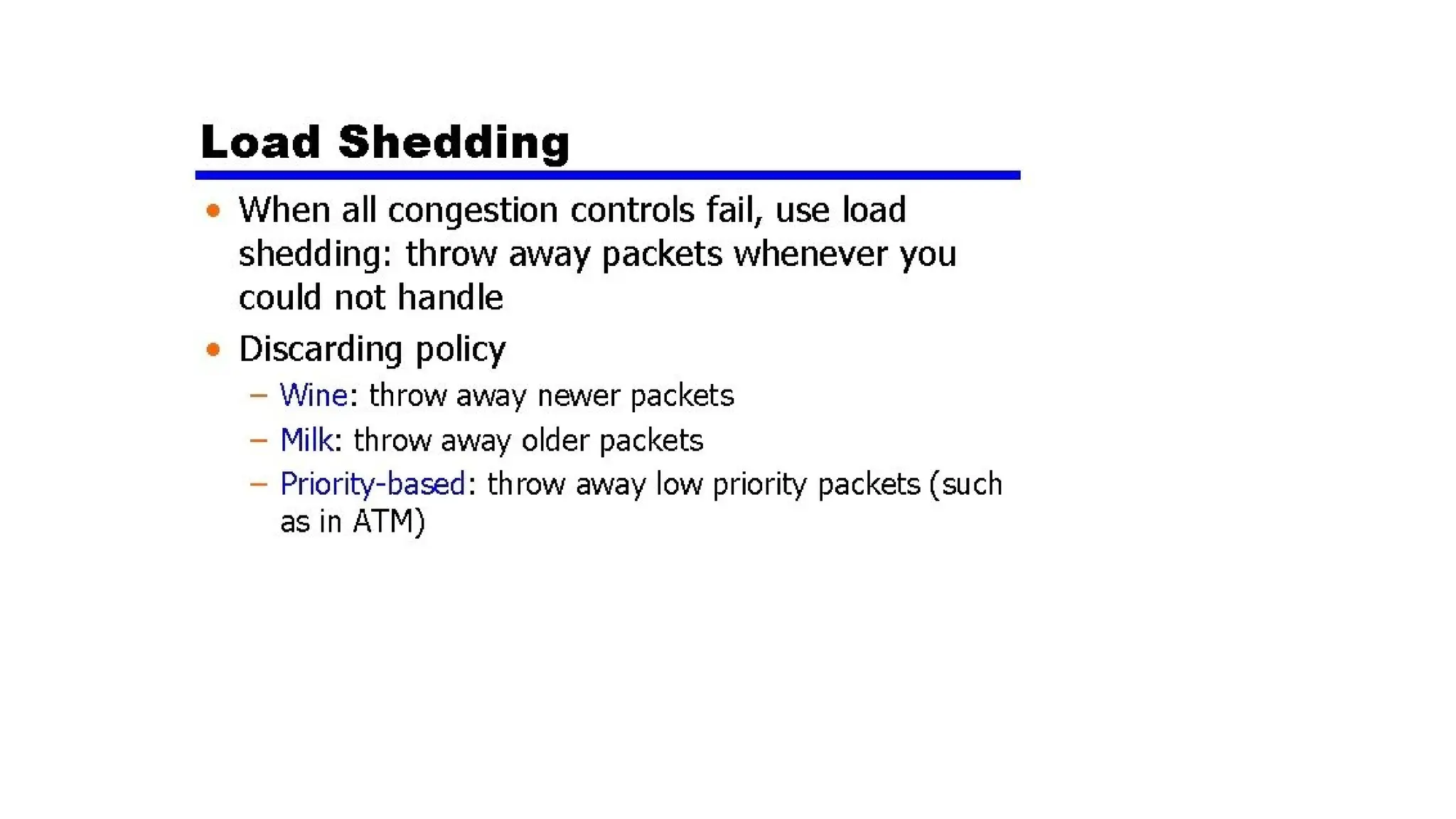
• Load Shedding
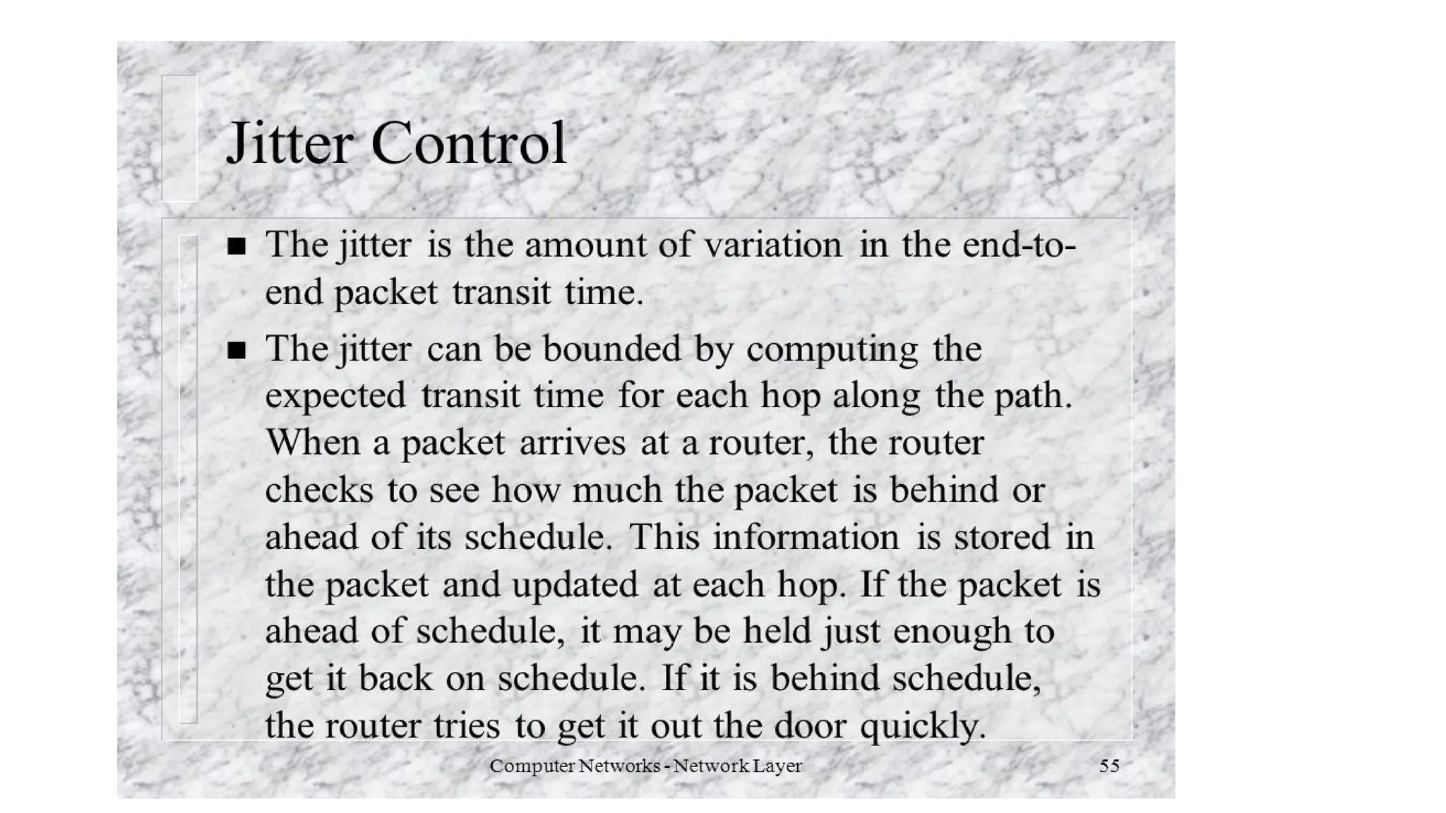
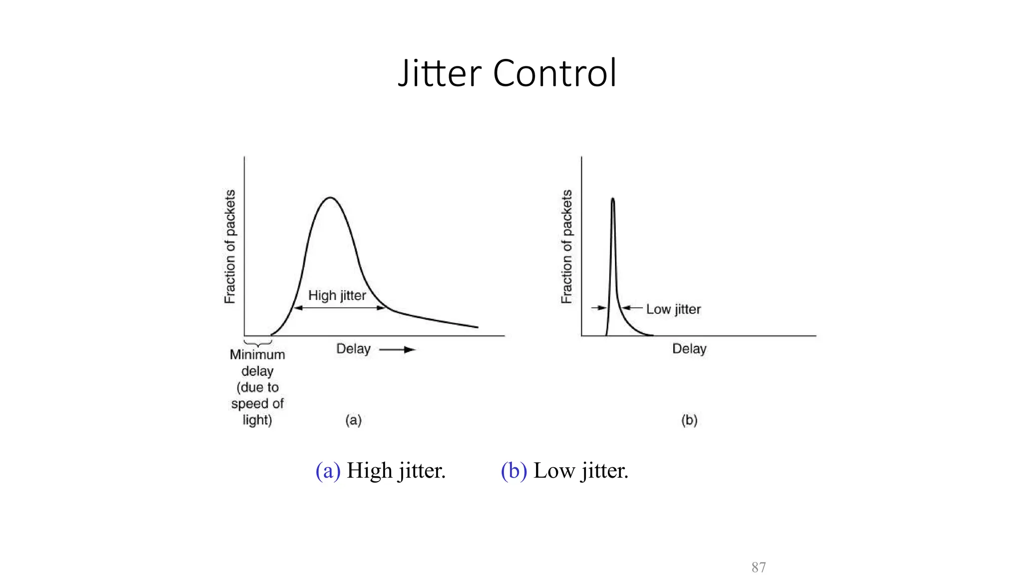
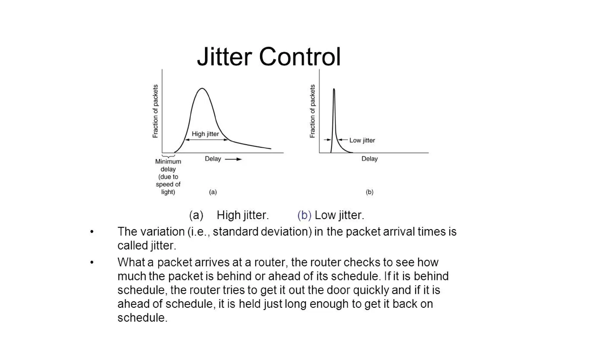
• Jitter Control
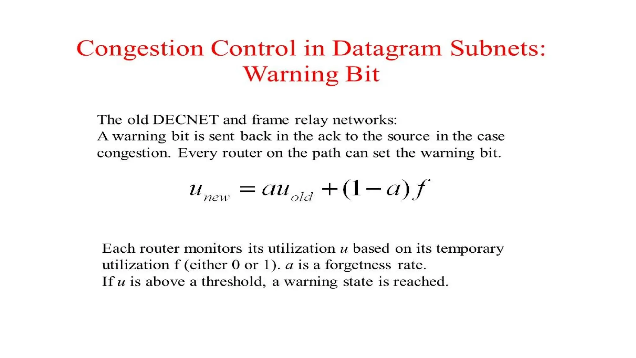
• A specialbit (warning bit) in the packet header is set by the
router to warn the source when congestion is detected.
• The bit is copied and piggy-backed on the ACK and sent to the
sender.
• The sender monitors the number of ACK packets it receives
with the warning bit set and adjusts its transmission rate
accordingly.
• The usual purpose of piggybacking is simply to gain free network access rather than any malicious intent, but it
can slow down data transfer for legitimate users of the network. Piggybacking is sometimes referred to as "Wi-Fi
squatting
72.
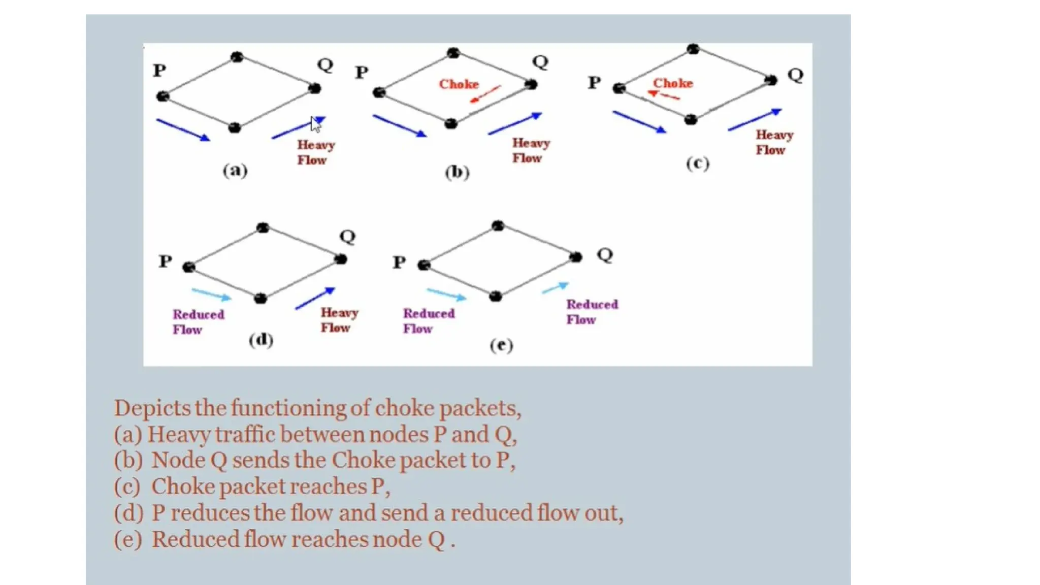
A choke packet
Achoke packet is used in network maintenance and quality
management to inform a specific node or transmitter that its
transmitted traffic is creating congestion over the network.
This forces the node or transmitter to reduce its output rate.
Choke packets are used for congestion and flow control over a
network
76.
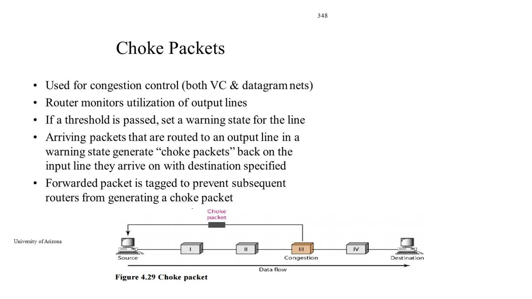
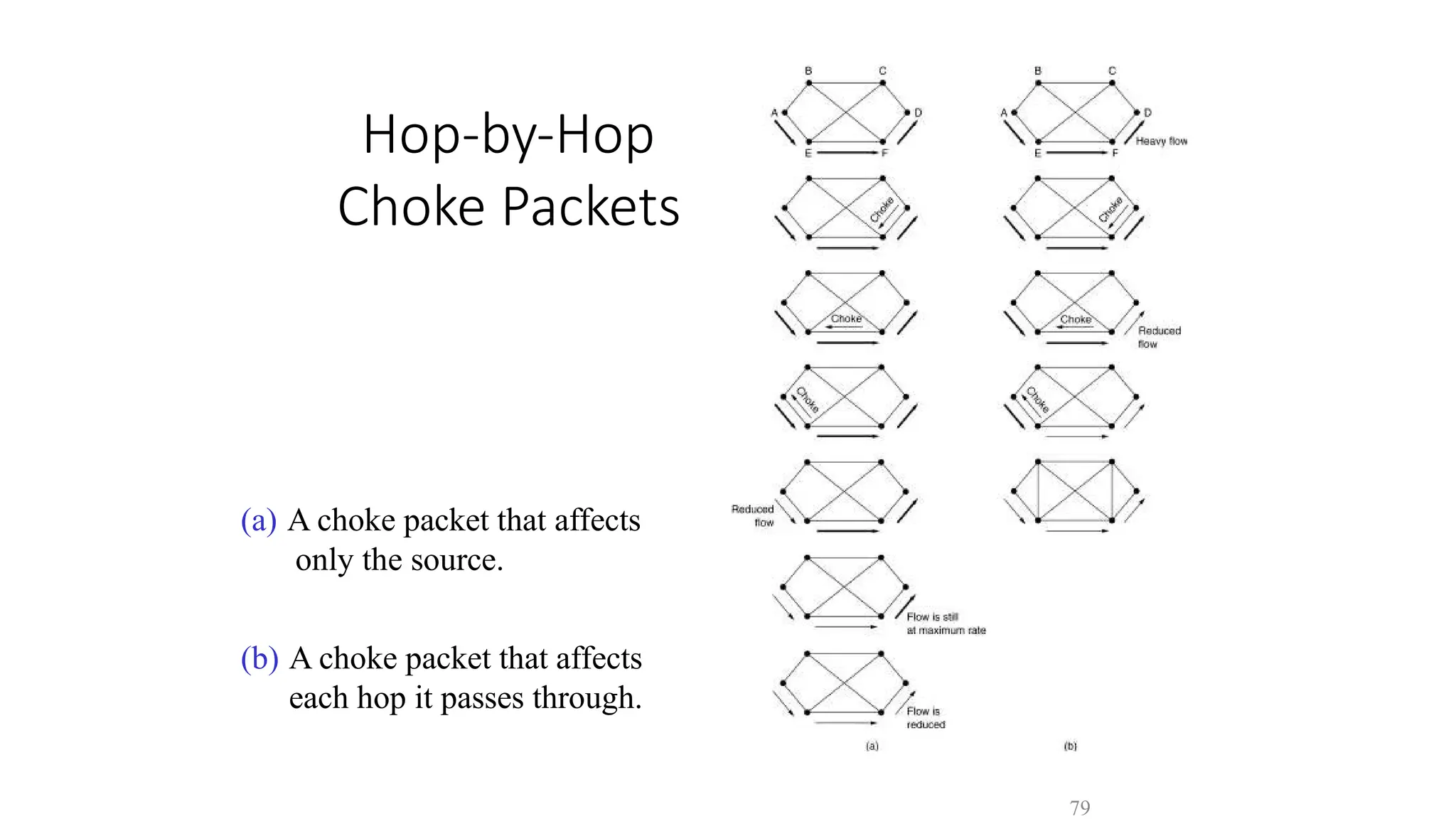
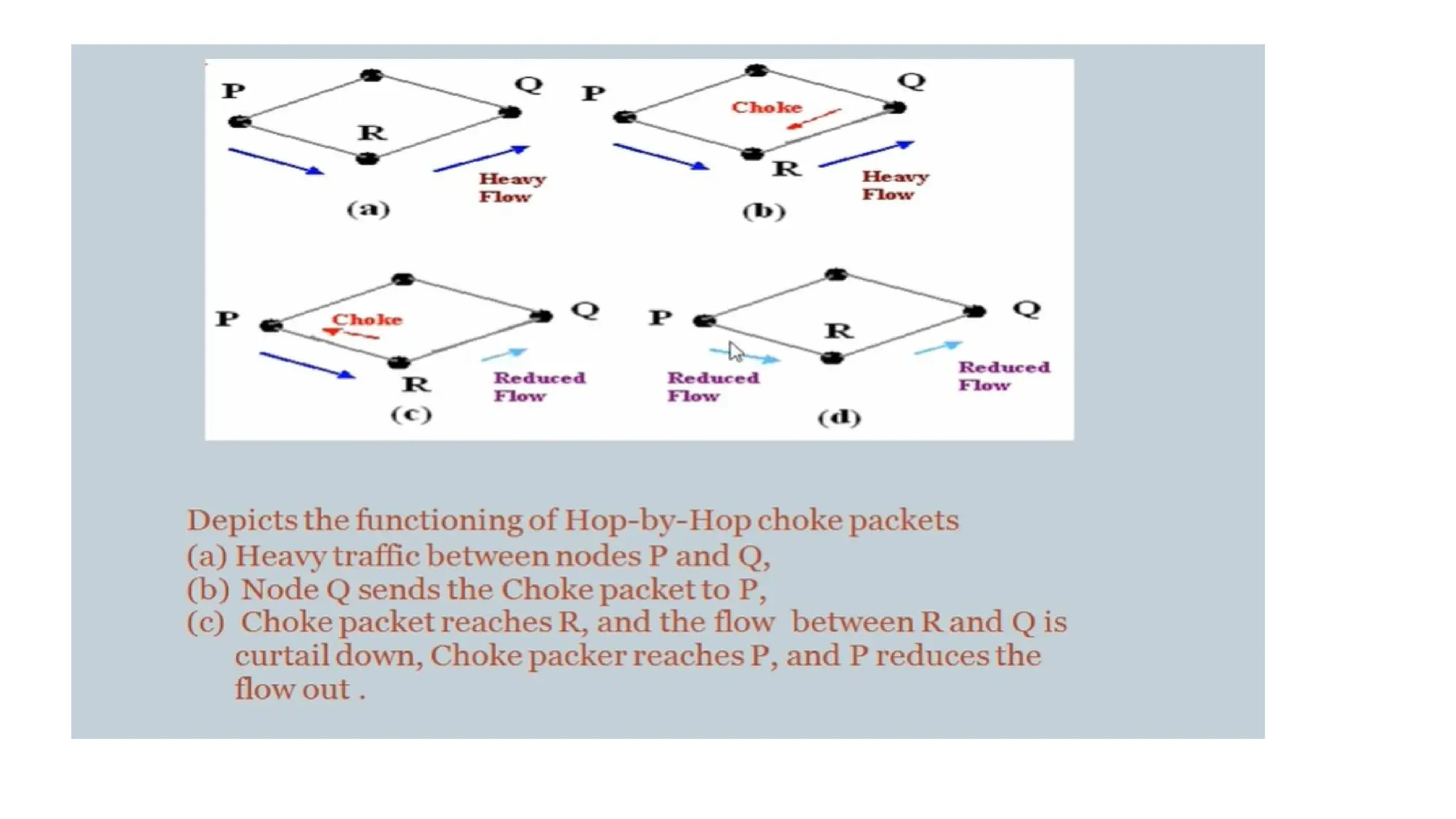
Hop-by-Hop
Choke Packets
(a) Achoke packet that affects
only the source.
(b) A choke packet that affects
each hop it passes through.
79
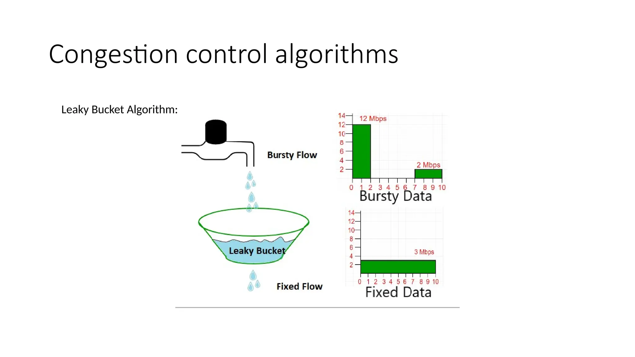
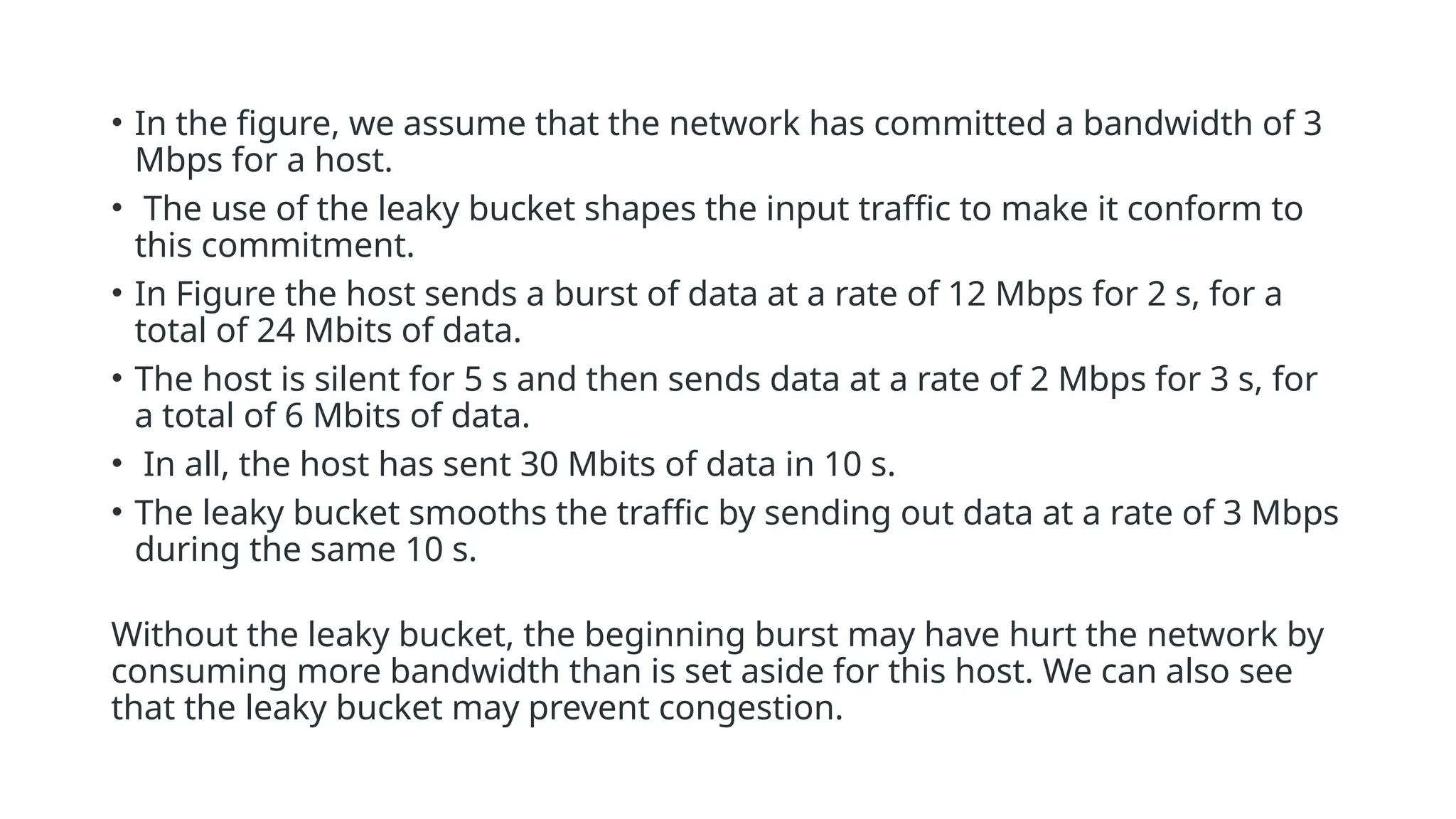
• In thefigure, we assume that the network has committed a bandwidth of 3
Mbps for a host.
• The use of the leaky bucket shapes the input traffic to make it conform to
this commitment.
• In Figure the host sends a burst of data at a rate of 12 Mbps for 2 s, for a
total of 24 Mbits of data.
• The host is silent for 5 s and then sends data at a rate of 2 Mbps for 3 s, for
a total of 6 Mbits of data.
• In all, the host has sent 30 Mbits of data in 10 s.
• The leaky bucket smooths the traffic by sending out data at a rate of 3 Mbps
during the same 10 s.
Without the leaky bucket, the beginning burst may have hurt the network by
consuming more bandwidth than is set aside for this host. We can also see
that the leaky bucket may prevent congestion.
88.
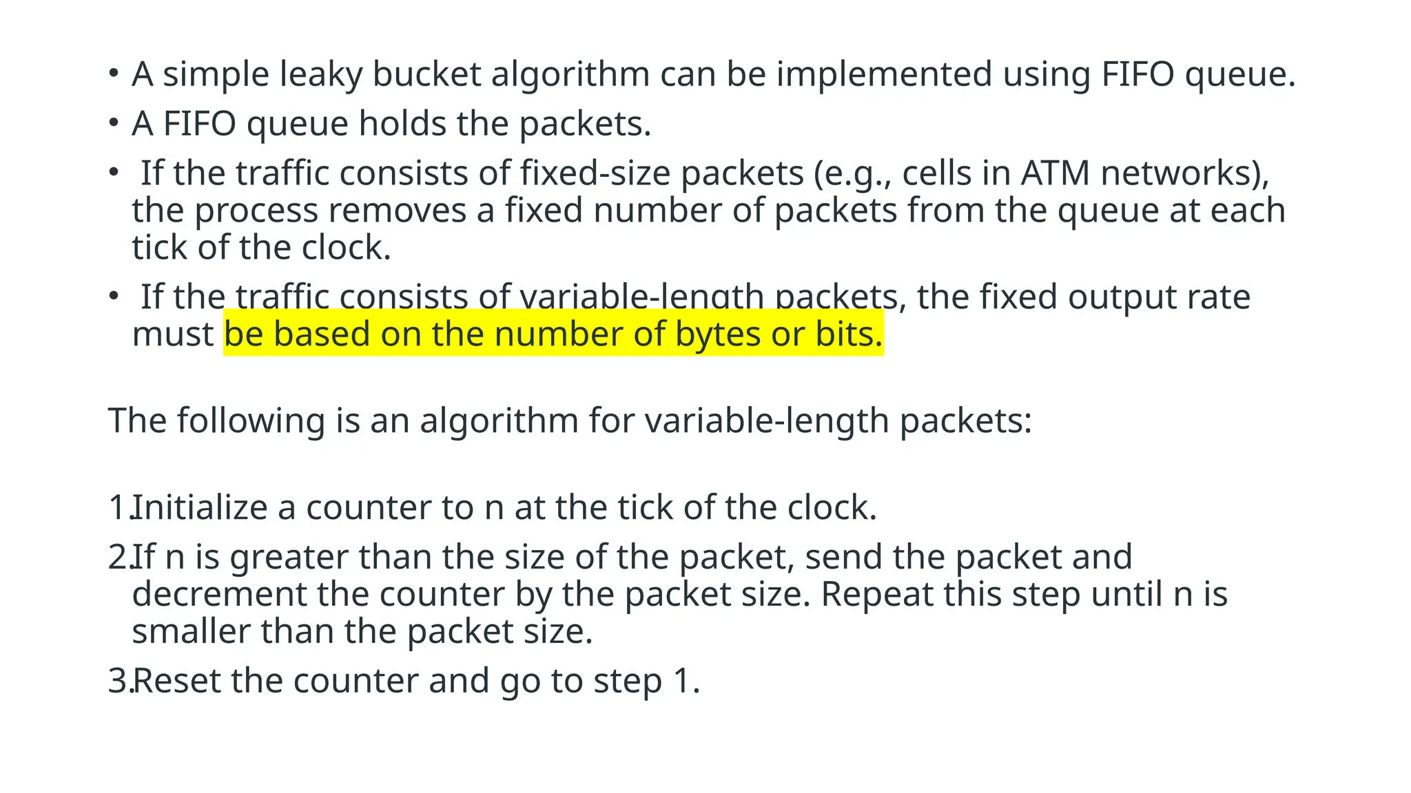
• A simpleleaky bucket algorithm can be implemented using FIFO queue.
• A FIFO queue holds the packets.
• If the traffic consists of fixed-size packets (e.g., cells in ATM networks),
the process removes a fixed number of packets from the queue at each
tick of the clock.
• If the traffic consists of variable-length packets, the fixed output rate
must be based on the number of bytes or bits.
The following is an algorithm for variable-length packets:
1.Initialize a counter to n at the tick of the clock.
2.If n is greater than the size of the packet, send the packet and
decrement the counter by the packet size. Repeat this step until n is
smaller than the packet size.
3.Reset the counter and go to step 1.
89.
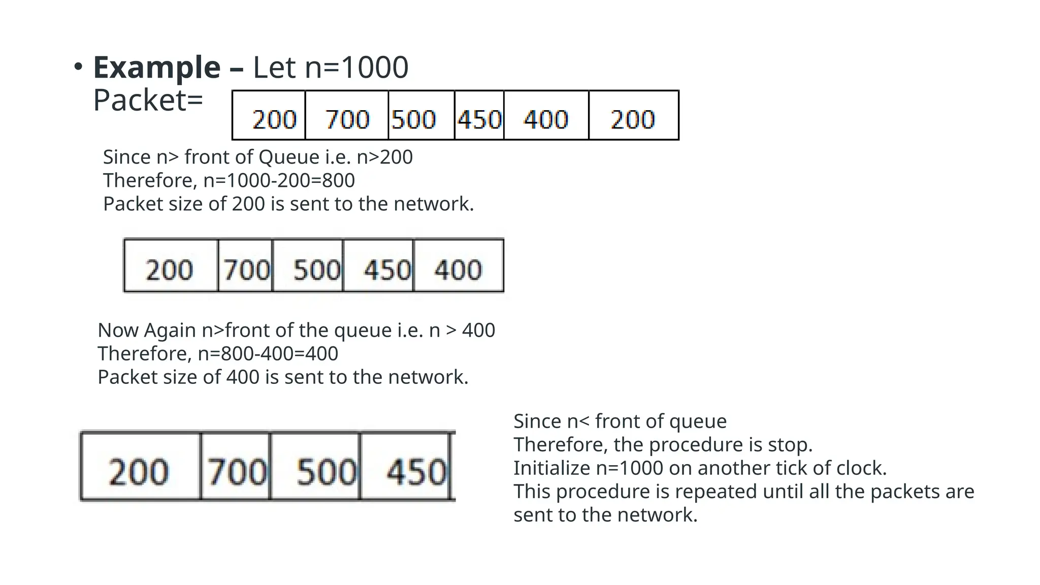
• Example –Let n=1000
Packet=
Since n> front of Queue i.e. n>200
Therefore, n=1000-200=800
Packet size of 200 is sent to the network.
Now Again n>front of the queue i.e. n > 400
Therefore, n=800-400=400
Packet size of 400 is sent to the network.
Since n< front of queue
Therefore, the procedure is stop.
Initialize n=1000 on another tick of clock.
This procedure is repeated until all the packets are
sent to the network.
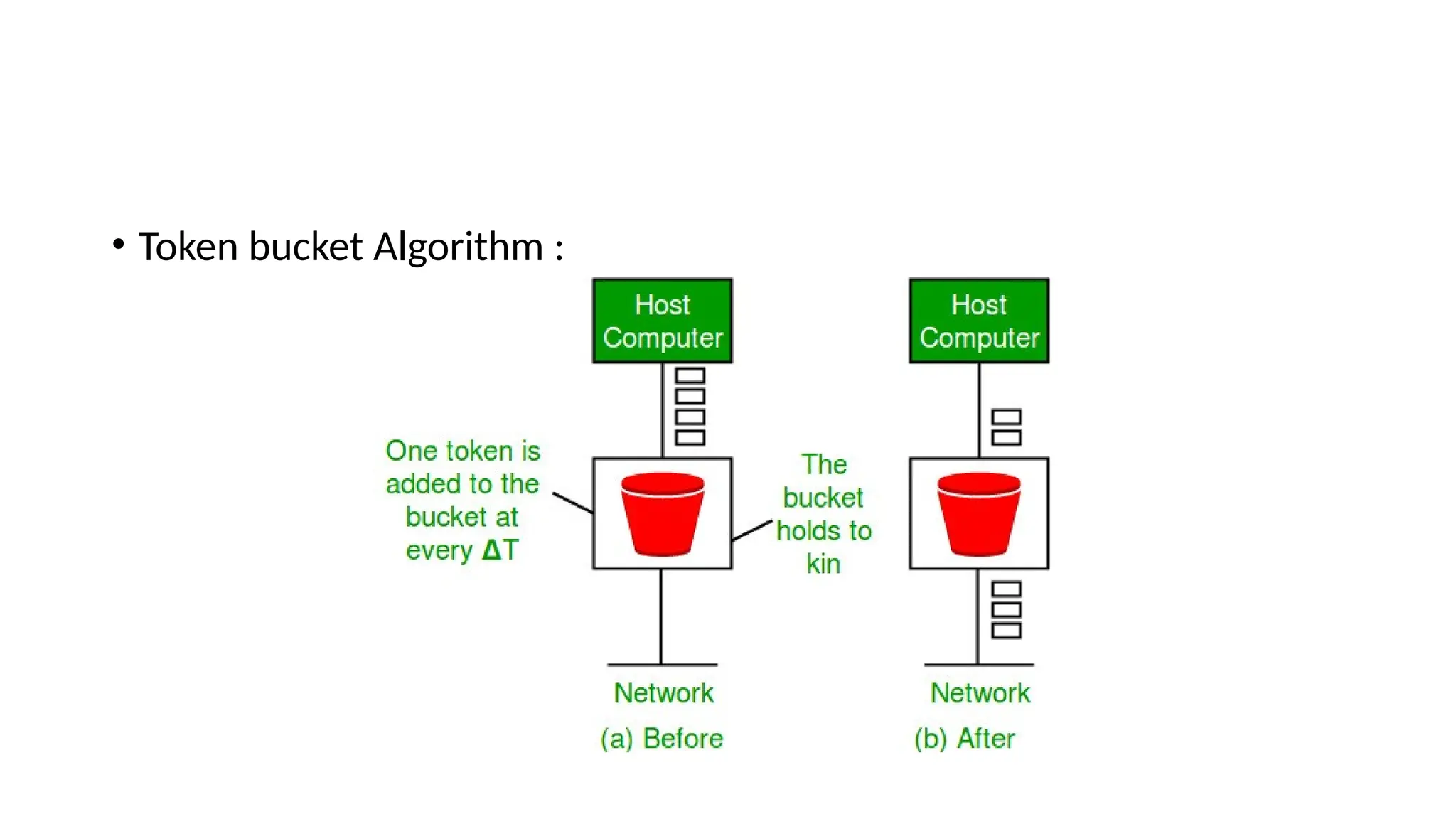
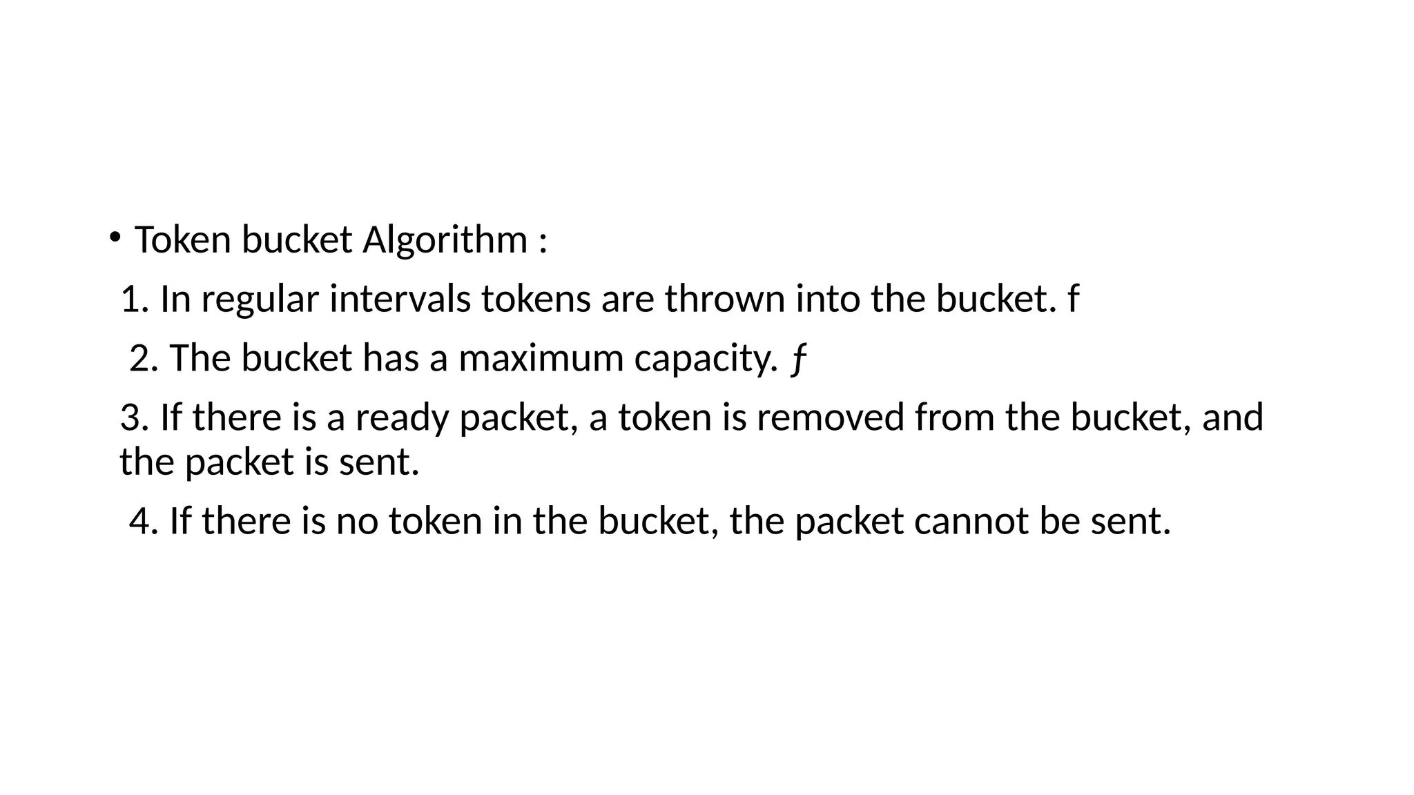
• Token bucketAlgorithm :
1. In regular intervals tokens are thrown into the bucket. f
2. The bucket has a maximum capacity. ƒ
3. If there is a ready packet, a token is removed from the bucket, and
the packet is sent.
4. If there is no token in the bucket, the packet cannot be sent.
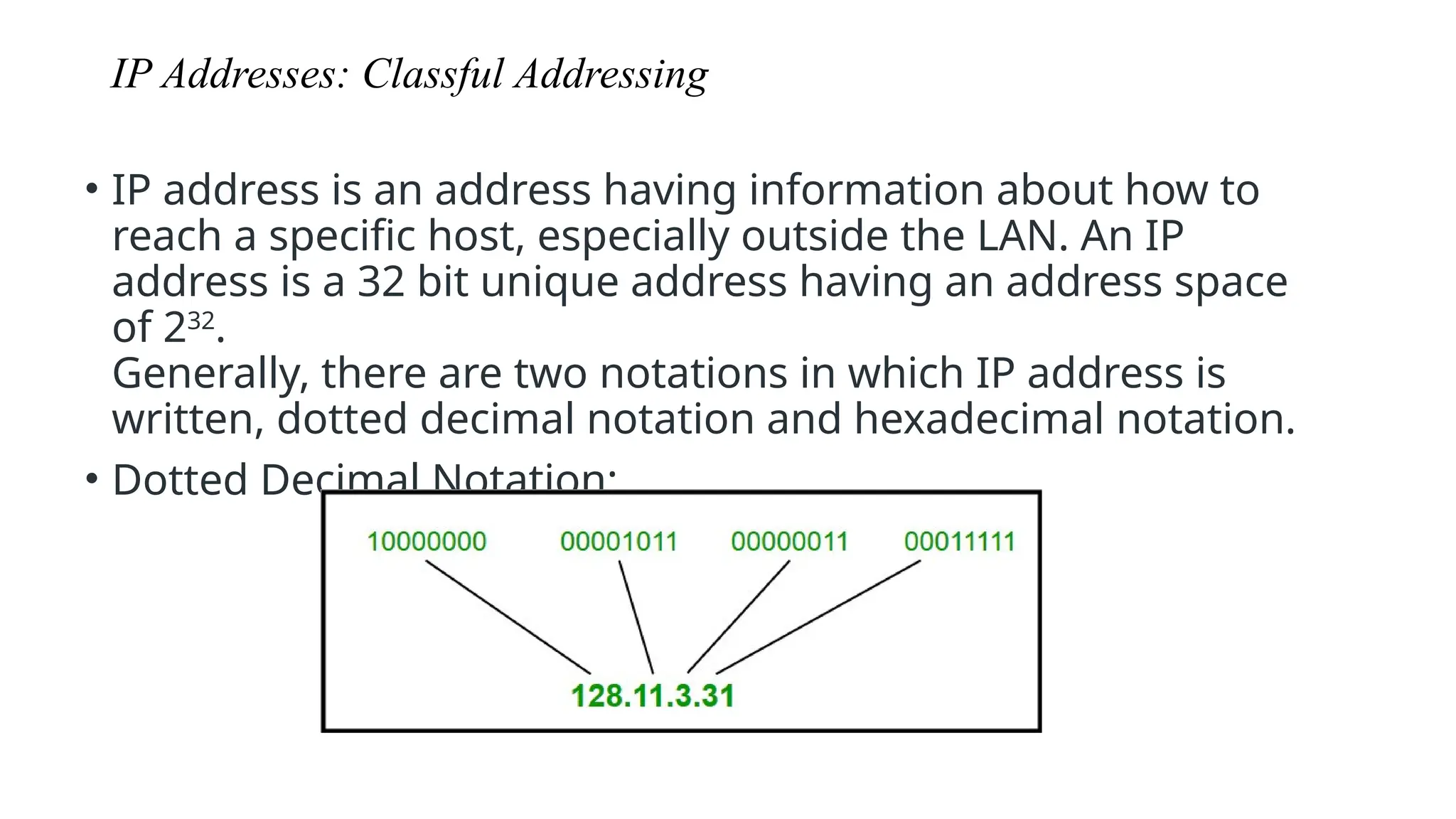
IP Addresses: ClassfulAddressing
• IP address is an address having information about how to
reach a specific host, especially outside the LAN. An IP
address is a 32 bit unique address having an address space
of 232
.
Generally, there are two notations in which IP address is
written, dotted decimal notation and hexadecimal notation.
• Dotted Decimal Notation:
95.
4.2 CLASSFUL ADDRESSING
IPaddresses, when started a few decades ago, used
the concept of classes. This architecture is called
classful addressing. In the mid-1990s, a new
architecture, called classless addressing, was
introduced and will eventually supersede the original
architecture. However, part of the Internet is still
using classful addressing, but the migration is very
fast.
96.
Some points tobe noted about dotted decimal notation:
1.The value of any segment (byte) is between 0 and 255 (both included).
2.There are no zeroes preceding the value in any segment (054 is wrong, 54 is
correct).
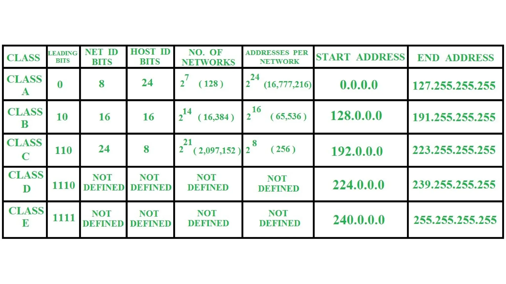
Classful Addressing
The 32 bit IP address is divided into five sub-classes. These are:
•Class A
•Class B
•Class C
•Class D
97.
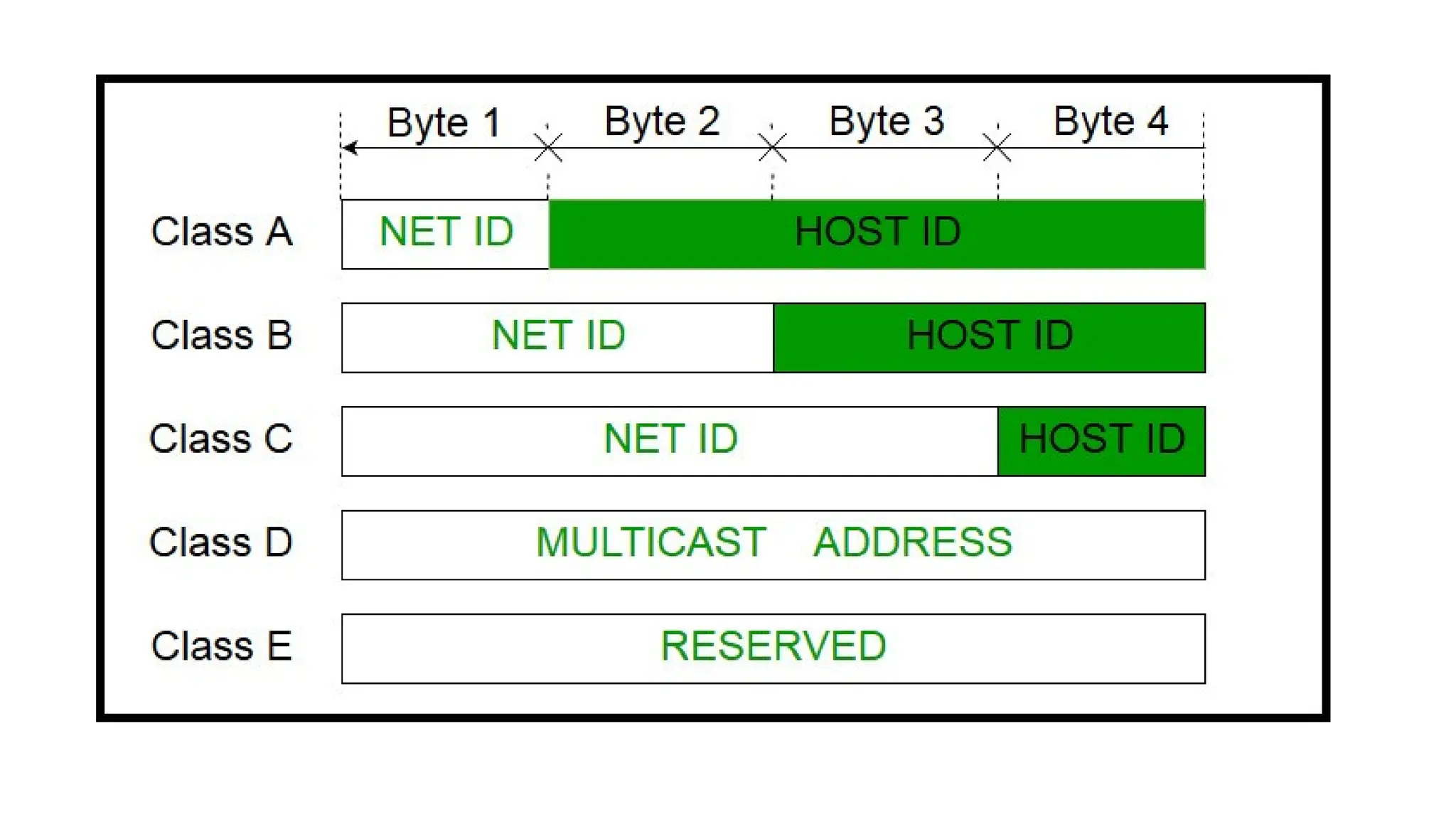
Each of theseclasses has a valid range of IP addresses. Classes D
and E are reserved for multicast and experimental purposes
respectively. The order of bits in the first octet determine the
classes of IP address.
IPv4 address is divided into two parts:
•Network ID
•Host ID
The class of IP address is used to determine the bits used for
network ID and host ID and the number of total networks and
hosts possible in that particular class.
Each ISP or network administrator assigns IP address to each
device that is connected to its network.
99.
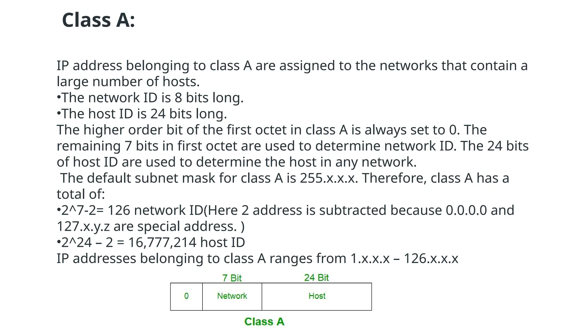
Class A:
IP addressbelonging to class A are assigned to the networks that contain a
large number of hosts.
•The network ID is 8 bits long.
•The host ID is 24 bits long.
The higher order bit of the first octet in class A is always set to 0. The
remaining 7 bits in first octet are used to determine network ID. The 24 bits
of host ID are used to determine the host in any network.
The default subnet mask for class A is 255.x.x.x. Therefore, class A has a
total of:
•2^7-2= 126 network ID(Here 2 address is subtracted because 0.0.0.0 and
127.x.y.z are special address. )
•2^24 – 2 = 16,777,214 host ID
IP addresses belonging to class A ranges from 1.x.x.x – 126.x.x.x
100.
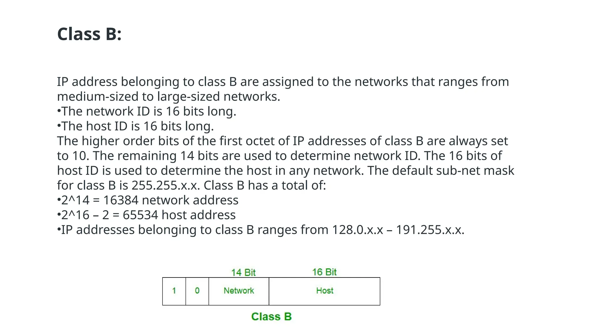
Class B:
IP addressbelonging to class B are assigned to the networks that ranges from
medium-sized to large-sized networks.
•The network ID is 16 bits long.
•The host ID is 16 bits long.
The higher order bits of the first octet of IP addresses of class B are always set
to 10. The remaining 14 bits are used to determine network ID. The 16 bits of
host ID is used to determine the host in any network. The default sub-net mask
for class B is 255.255.x.x. Class B has a total of:
•2^14 = 16384 network address
•2^16 – 2 = 65534 host address
•IP addresses belonging to class B ranges from 128.0.x.x – 191.255.x.x.
101.
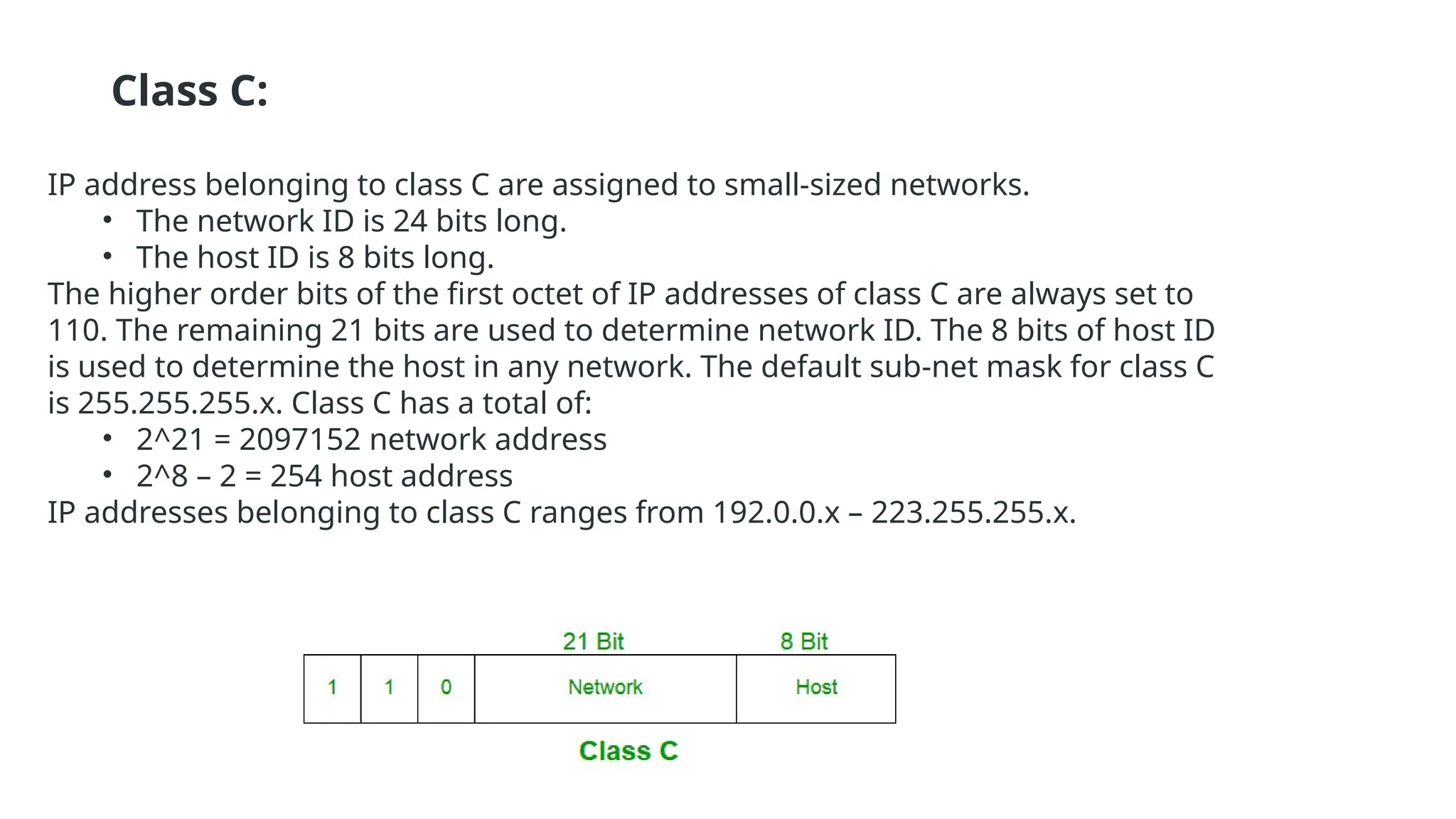
Class C:
IP addressbelonging to class C are assigned to small-sized networks.
• The network ID is 24 bits long.
• The host ID is 8 bits long.
The higher order bits of the first octet of IP addresses of class C are always set to
110. The remaining 21 bits are used to determine network ID. The 8 bits of host ID
is used to determine the host in any network. The default sub-net mask for class C
is 255.255.255.x. Class C has a total of:
• 2^21 = 2097152 network address
• 2^8 – 2 = 254 host address
IP addresses belonging to class C ranges from 192.0.0.x – 223.255.255.x.
102.
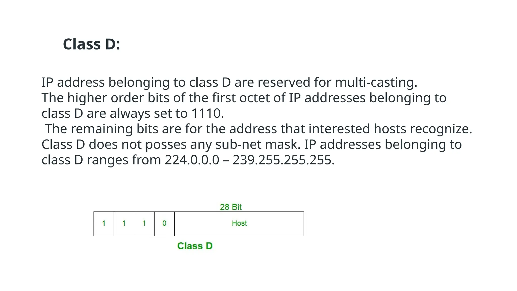
Class D:
IP addressbelonging to class D are reserved for multi-casting.
The higher order bits of the first octet of IP addresses belonging to
class D are always set to 1110.
The remaining bits are for the address that interested hosts recognize.
Class D does not posses any sub-net mask. IP addresses belonging to
class D ranges from 224.0.0.0 – 239.255.255.255.
104.
An IPpacket is the smallest message entity exchanged via
the Internet Protocol across an IP network.
IP packets consist of a header for addressing and routing,
and a payload for user data.
The header contains information about IP version, source IP
address, destination IP address, time-to-live, etc.
DETAILS OF IP PACKET
105.
IPv4:
IPv4 is aconnectionless protocol used for packet-switched networks.
It operates on a best effort delivery model, in which neither delivery is
guaranteed, nor proper sequencing or avoidance of duplicate delivery is
assured.
Internet Protocol Version 4 (IPv4) is the fourth revision of the Internet Protocol
and a widely used protocol in data communication over different kinds of
networks.
IPv4 is a connectionless protocol used in packet-switched layer networks, such
as Ethernet.
It provides a logical connection between network devices by providing
identification for each device.
106.
IPv4 isdefined and specified in IETF publication RFC 791.
IPv4 uses 32-bit addresses for Ethernet communication in five classes: A, B, C, D and
E.
Classes A, B and C have a different bit length for addressing the network host.
Class D addresses are reserved for military purposes, while class E addresses are
reserved for future use.
IPv4 uses 32-bit (4 byte) addressing, which gives 232
addresses.
IPv4 addresses are written in the dot-decimal notation, which comprises of four
octets of the address expressed individually in decimal and separated by periods,
for instance, 192.168.1.5.
110.
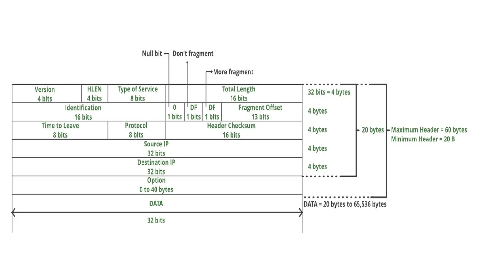
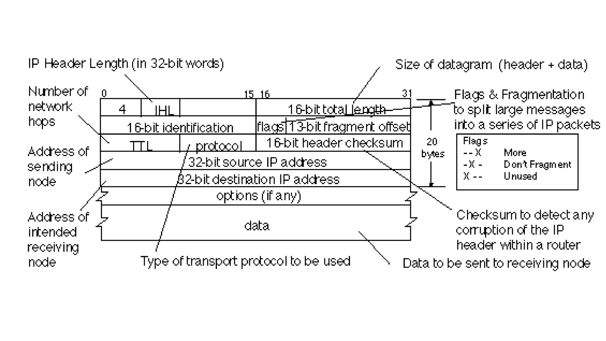
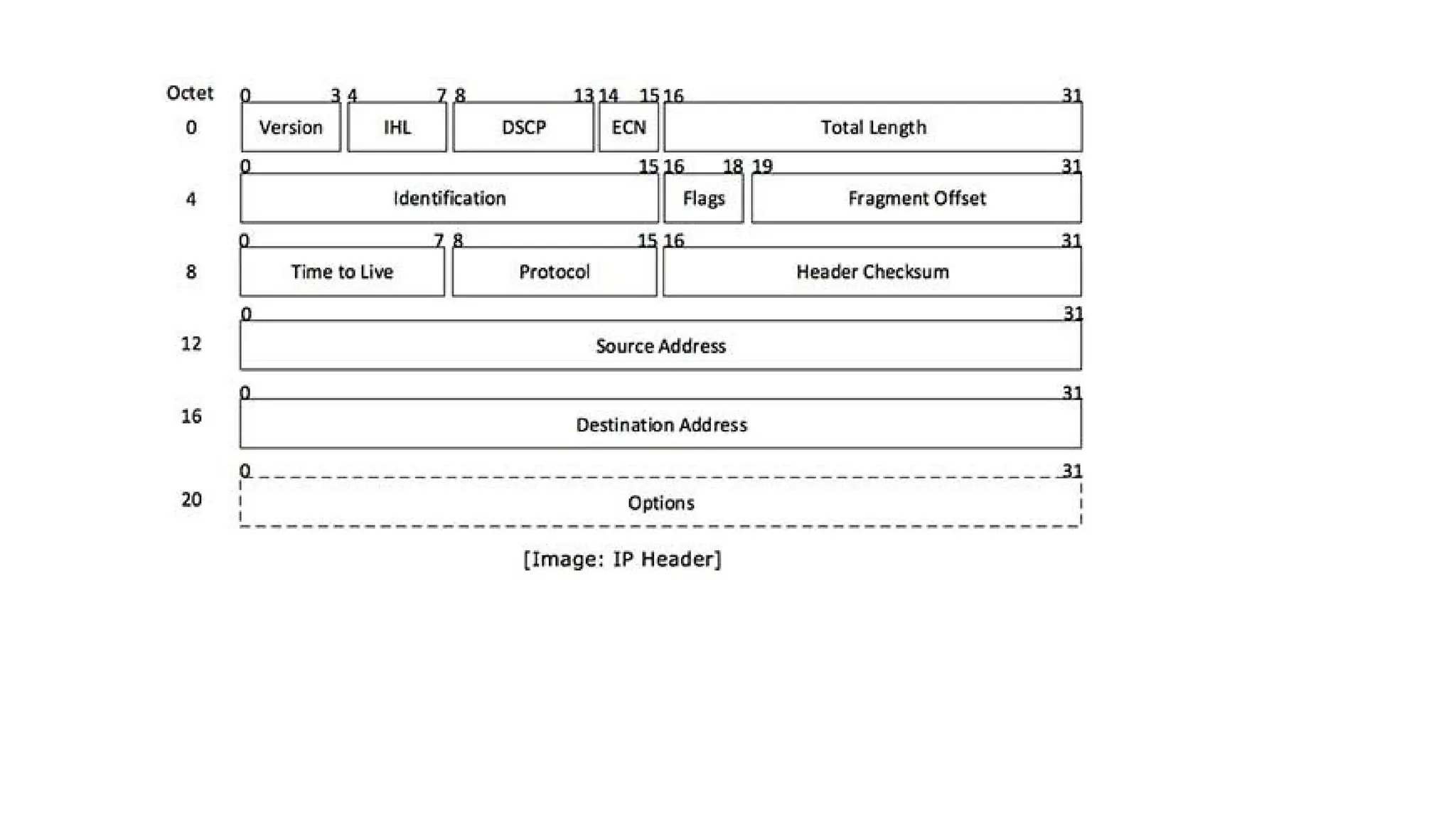
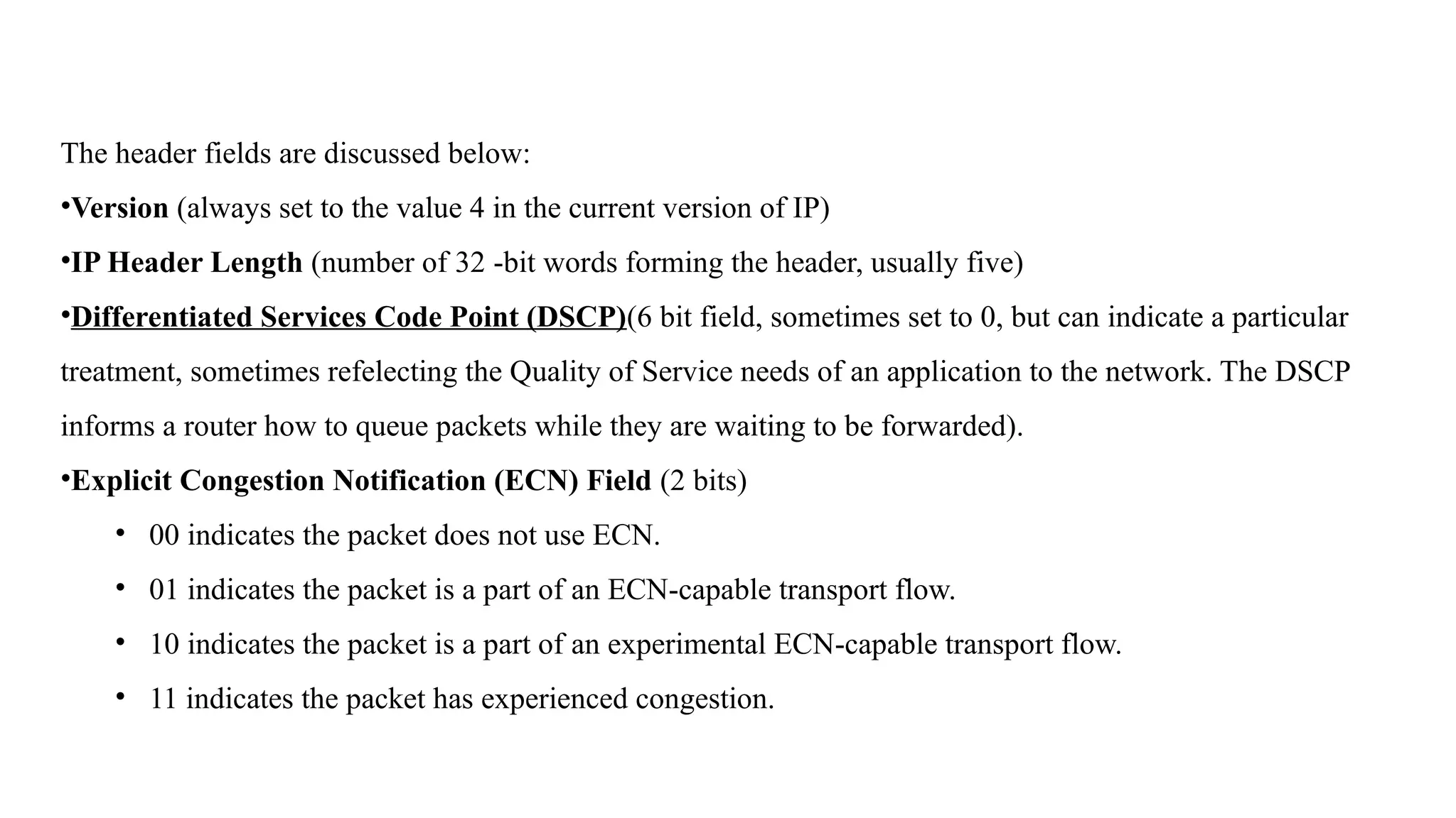
The header fieldsare discussed below:
•Version (always set to the value 4 in the current version of IP)
•IP Header Length (number of 32 -bit words forming the header, usually five)
•Differentiated Services Code Point (DSCP)(6 bit field, sometimes set to 0, but can indicate a particular
treatment, sometimes refelecting the Quality of Service needs of an application to the network. The DSCP
informs a router how to queue packets while they are waiting to be forwarded).
•Explicit Congestion Notification (ECN) Field (2 bits)
• 00 indicates the packet does not use ECN.
• 01 indicates the packet is a part of an ECN-capable transport flow.
• 10 indicates the packet is a part of an experimental ECN-capable transport flow.
• 11 indicates the packet has experienced congestion.
111.
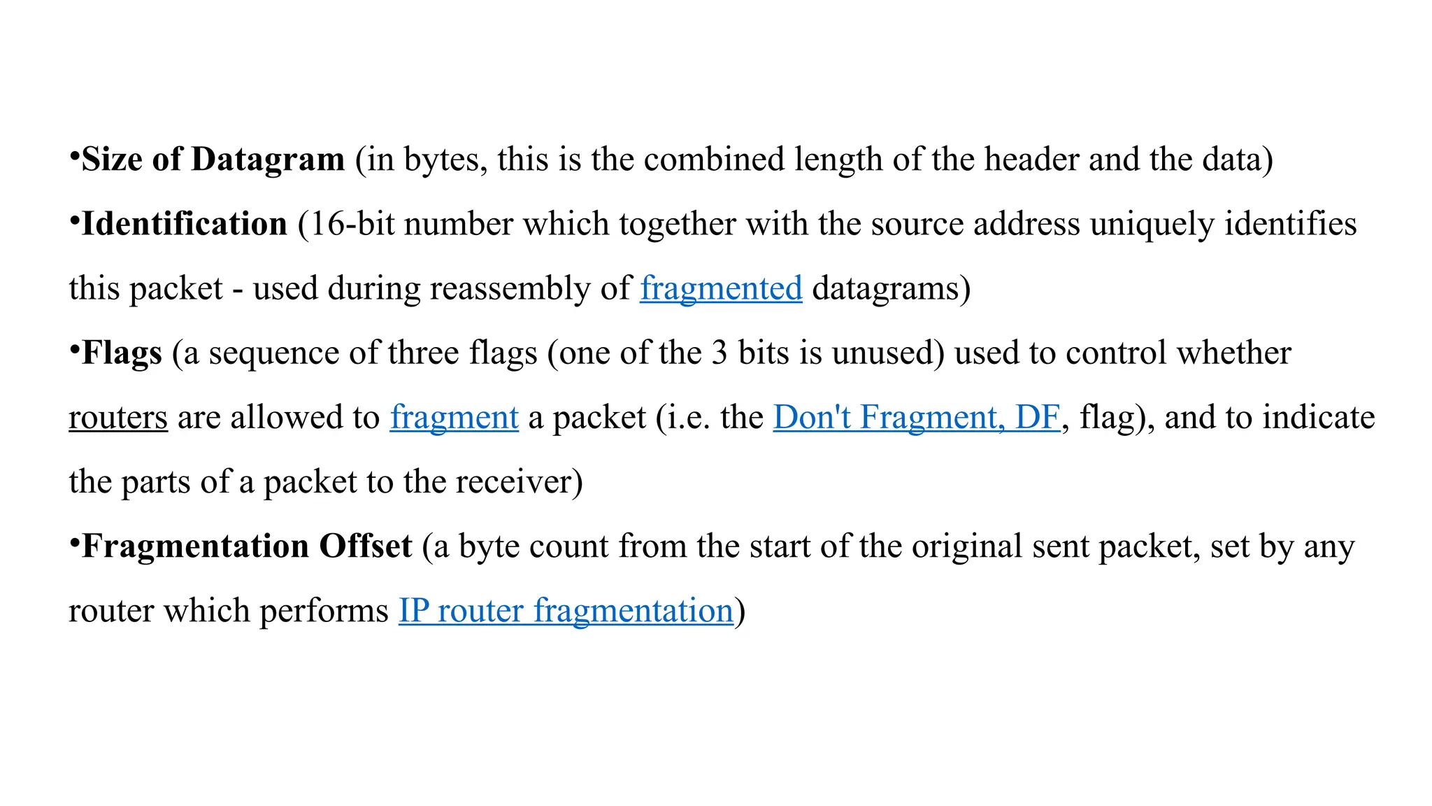
•Size of Datagram(in bytes, this is the combined length of the header and the data)
•Identification (16-bit number which together with the source address uniquely identifies
this packet - used during reassembly of fragmented datagrams)
•Flags (a sequence of three flags (one of the 3 bits is unused) used to control whether
routers are allowed to fragment a packet (i.e. the Don't Fragment, DF, flag), and to indicate
the parts of a packet to the receiver)
•Fragmentation Offset (a byte count from the start of the original sent packet, set by any
router which performs IP router fragmentation)
112.
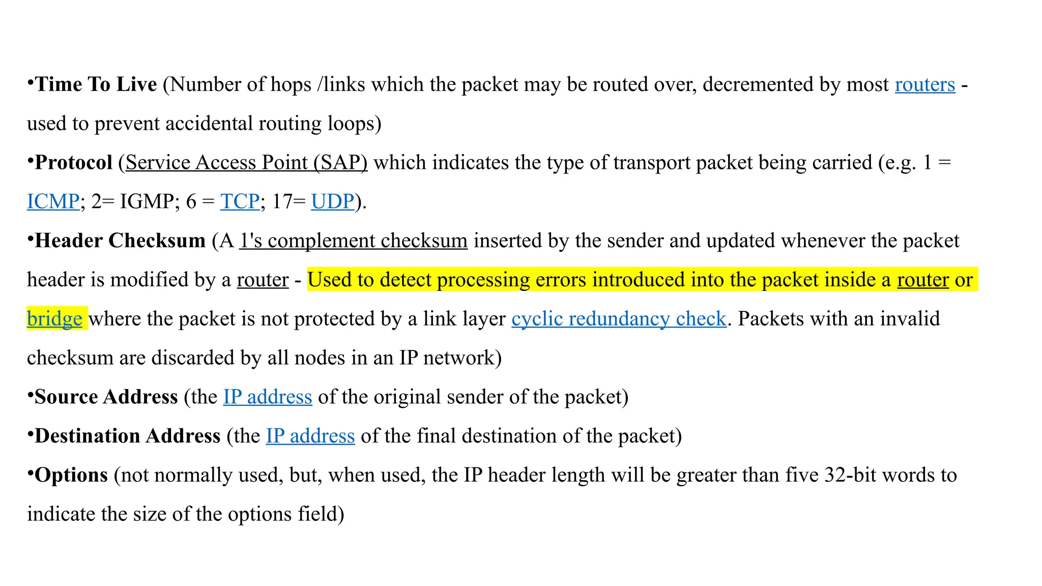
•Time To Live(Number of hops /links which the packet may be routed over, decremented by most routers -
used to prevent accidental routing loops)
•Protocol (Service Access Point (SAP) which indicates the type of transport packet being carried (e.g. 1 =
ICMP; 2= IGMP; 6 = TCP; 17= UDP).
•Header Checksum (A 1's complement checksum inserted by the sender and updated whenever the packet
header is modified by a router - Used to detect processing errors introduced into the packet inside a router or
bridge where the packet is not protected by a link layer cyclic redundancy check. Packets with an invalid
checksum are discarded by all nodes in an IP network)
•Source Address (the IP address of the original sender of the packet)
•Destination Address (the IP address of the final destination of the packet)
•Options (not normally used, but, when used, the IP header length will be greater than five 32-bit words to
indicate the size of the options field)
113.
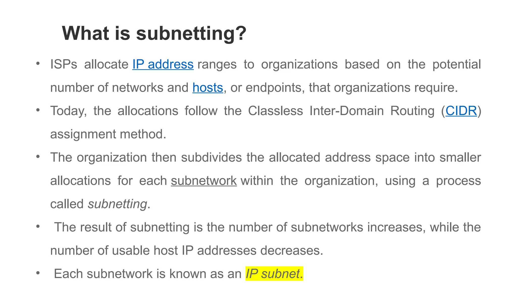
• ISPs allocateIP address ranges to organizations based on the potential
number of networks and hosts, or endpoints, that organizations require.
• Today, the allocations follow the Classless Inter-Domain Routing (CIDR)
assignment method.
• The organization then subdivides the allocated address space into smaller
allocations for each subnetwork within the organization, using a process
called subnetting.
• The result of subnetting is the number of subnetworks increases, while the
number of usable host IP addresses decreases.
• Each subnetwork is known as an IP subnet.
What is subnetting?


![Unit-3-Part-1 [Autosaved].ppt](https://cdn.slidesharecdn.com/ss_thumbnails/unit-3-part-1autosaved-230216062941-16596250-thumbnail.jpg?width=640&height=640&fit=bounds)