The document describes the NFS-320 intelligent fire alarm control panel. It has the following key features:
- It is part of the ONYX series of fire alarm controls and can be used in stand-alone or networked configurations.
- It has an isolated intelligent signaling line circuit that can connect up to 159 detectors and 159 modules.
- Additional optional modules allow it to interface with wireless devices and provide additional notification and control functions.
The D.T.MUX Sentinel Crash protected Airborne Data Recorder, is fully integrated solution in a lightweight compact system (FDR/CVR/AIR) providing crash-protected recording of flight data, audio, and image/video (Full HD 1080p 30fps) on lightweight helicopters and fixed-wing aircrafts. More than a simple recorder the unit can replace a Data Acquisition system with the advantage of crash protection. He has been designed to capture any type of data source, by serial bus or by internal Sensor to complete missing data. It can be used with all functions or just a one. This unit can cover “Crash requirements” of the ED-155 or ED-112 standard and can be easily integrated to any type of aircraft.
The D.T.MUX Nano Airborne Data Recorder, is a powerful miniature unit (Available in two form factor) with recoding capacity on Solid State Disk (SSD) from 32GB to 2TB, support Military Grade Encryption/Erasure and Physical Destruction. IRIG 106 Chapter 10 Compliant. An ultra-compact and standalone airborne data logging unit, with a quick access removable media of solid state flash memory, who permit an easy data retrieval at the exploitation center. D.T.MUX Nano can be built to meet your customized configuration. This device is particularly adapted to mission use, like surveillance and reconnaissance activity
The NanoX acquisition system is an efficient data concentrator and recorder, with an ultra-compact design, and an ease of changing acquisition modules. The NanoX provide modularity and permit to plug/stack until sixteen data acquisition modules by unit. A unit is constituted by a CPU/Controller module with a optional recording capacity (from 32GB to 2TB) and a smart power supply module. The NanoX is a data acquisition concentrator completed with high speed (1Gbps) recording and transmitting system combined in the same device, with this device you can make all in one modular and compact solution where other solutions require two or three separate units.
HUBUNGI KAMI : PT.MINDS INDO SURVEY, DISTRIBUTOR ALAT UKUR SURVEY DAN PEMETAAN, KOMP/RUKO. MEGA KALIMALANG KAV. 8 JLN KH NOER ALI NO. 11,PEKAYON JAYA BEKASI, Tlp : 02195099644/ HP : 082119953499/ 087886144398 Pin BB : 237FC845 .
PENGIRIMAN GRATIS UNTUK WILAYAH DKI
Menjual Alat-Alat Untuk Survey Pemetaan, Infrastruktur, Kontraktor, Telekomunikasi, Pertambangan, Geologist, Exploration, Mining, Dirling, Kelautan, Militer, Migas, Pembangunan Pembangunan, Pengelolaan Lahan Lahan Perhutanan Dan Perkebunan Kelapa Sawit.
RUANG LINGKUP KEGIATAN
PENJUALAN, SERVICE / PERBAIKAN DAN PENYEWAAN ALAT-ALAT UKUR
PENJUALAN :
Alat Ukur
- Total Station
- Altimeter
- Theodolite
- Digital Planimeter
- Levels
- Walking Measure
- GPS Geodetic
- Digital Level / Smart Tool
- Compass
- Phantograph
- Clinometer
- Tandem / Clino - Compass
Accessories :
- Tripod
- Prisma
- Rambu Ukur
- Meteran
- Jalon
- Binocular
PENYEWAAN :
- Total Station
- Automatic Level
- Theodolite
MEREK ALAT UKUR YANG TERSEDIA :
- MINDS
- SPECTRA
- NIKON
- SUUNTO
- GARMIN
- LEICA
- HORIZON
SERVICE / PERBAIKAN DAN KALIBRASI MACAM-MACAM ALAT UKUR
HARGA MENARIK / COMPETITIVE
Catatan : Price List akan dikirim sesuai permintaan
Nanometrics TitanSMA e TitanEA: accelerografi strong motion per il monitoraggio di grandi infrastrutture come reattori nucleari, edifici a più piani, ponti e dighe.
Microcontrolador STM32WL55 - Fazendo uma aplicação LORAWAN do zero em poucos ...Embarcados
Neste evento teremos a oportunidade de fazer uma aplicação LoRaWAN do zero, através do nosso IDE, fazendo todo o processo de seleção dos periféricos, configuração de I/Os, Modo Low Power,etc. Também conectar a Rede LoRa da American Tower e finalmente fazendo o controle das regras da aplicação pelo painel WEB da TAGO.
Mais detalhes em: https://www.embarcados.com.br/evento-online-microcontrolador-stm32wl55/
Objetivo do Webinar
Apresentação da solução BlueNRG-MESH e do SDK que é composto pelo firmware embarcado para a plataforma BlueNRG e a library para Android e iOS.
Convidados - José Ricardo de Freitas
É engenheiro sênior da STMicroelectronics. É formado em Engenharia Elétrica pela Escola de Engenharia Mauá e MBA em Administração de Empresas pela Fundação Getulio Vargas. Ele é responsável pelo desenvolvimento e suporte em aplicações de Sensores e Conectividade na STMicroelectronics na América do Sul.
Webinar: Nova família de microcontroladores STM32WL – Sub Giga MultiprotocoloEmbarcados
Neste webinar você vai conhecer o primeiro microcontrolador monolítico com radio Sub Giga multi protocolo (range de frequência: 150 MHz a 960 MHz , Modulações : LoRa®, (G)FSK, (G)MSK and BPSK ). Também será apresentado o Ambiente de desenvolvimento (CubeIDE) e outras ferramentas, mostrando um exemplo de uma aplicação LoRa.
Assista o webinar em: https://www.embarcados.com.br/webinar-nova-familia-de-microcontroladores-stm32wl-sub-giga-multiprotocolo/
Webinar: BlueNRG-LP - Bluetooth 5.2 de longo alcance para aplicações industriaisEmbarcados
O BlueNRG-LP é uma solução de SoC sem fio Bluetooth® Low Energy programável de ultrabaixa energia. Ele incorpora os IPs de rádio RF de 2,4 GHz de última geração da STMicroelectronics combinando desempenho incomparável com vida útil de bateria extremamente longa. É compatível com a especificação de núcleo Bluetooth® Low Energy SIG versão 5.2 endereçando conectividade ponto a ponto e rede Bluetooth Mesh e permite que redes de dispositivos em grande escala sejam estabelecidas de maneira confiável. O BlueNRG-LP também é adequado para comunicação sem fio de rádio proprietária de 2,4 GHz para lidar com aplicações de latência ultrabaixa.
Assista a gravação em: https://www.embarcados.com.br/webinars/webinar-bluenrg-lp-bluetooth-5-2-de-longo-alcance-para-aplicacoes-industriais/
Dewesoft is designing and manufacturing versatile and easy-to-use data acquisition systems. The products are the ultimate tools for every test and measurement engineer. The presentation includes products for automotive, aerospace, energy, civil engineering, industrial and heavy machinery.
1. DN-7112:N • 3/24/17 — Page 1 of 6
NFS-320
Intelligent Addressable
Fire Alarm System
Intelligent Fire Alarm Control Panels
DN-7112:N • A-14
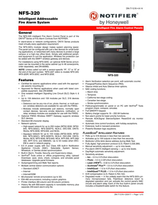
NFS-320
7112pho1.jpg
General
The NFS-320 intelligent Fire Alarm Control Panel is part of the
ONYX®
Series of Fire Alarm Controls from NOTIFIER.
In stand-alone or network configurations, ONYX Series products
meet virtually every application requirement.
The NFS-320’s modular design makes system planning easier.
The panel can be configured with just a few devices for small build-
ing applications, or networked with many devices to protect a large
campus or a high-rise office block. Simply add additional periph-
eral equipment to suit the application. Wireless fire protection can
be added with the SWIFT wireless gateway and devices.
For installations using NFS-320C, an optional ACM Series annun-
ciator can be mounted in the same cabinet (up to 48 zones/points,
order separately; see DN-60085).
NOTE: Unless called out with a version-specific “R”, “C” or “E” at
the end of the part number, “NFS-320” refers to models NFS-320,
NFS-320R, NFS-320C, and NFS-320E.
Features
• Certified for seismic applications when used with the appropri-
ate seismic mounting kit.
• Approved for Marine applications when used with listed com-
patible equipment. See DN-60688.
• One isolated intelligent Signaling Line Circuit (SLC) Style 4, 6
or 7.
• Up to 159 detectors and 159 modules per SLC; 318 devices
maximum.
– Detectors can be any mix of ion, photo, thermal, or multi-sen-
sor; wireless detectors are available for use with the FWSG.
– Modules include addressable pull stations, normally open
contact devices, two-wire smoke detectors, notification, or
relay; wireless modules are available for use with the FWSG.
• Optional FWSG Wireless SWIFT Gateway supports wireless
SLC devices.
• Standard 80-character display.
• Network options:
– High-speed network for up to 200 nodes (NFS2-3030, NFS2-
640, NFS-320(C), NFS-320SYS, NCA-2, DVC-EM, ONYX-
Works, NFS-3030, NFS-640, and NCA).
– Standard network for up to 103 nodes (NFS2-3030, NFS2-
640, NFS-320(C), NFS-320SYS, NCA-2, DVC-EM, ONYX-
Works, NCS, NFS-3030, NFS-640, NCA, AFP-200, AFP-300/
400, AFP-1010, and AM2020). Up to 54 nodes when DVC-
EM is used in network paging.
• 6.0 A power supply with four Class A/B built-in Notification
Appliance Circuits (NAC). Selectable System Sensor,
Wheelock, or Gentex strobe synchronization.
• Built-in Alarm, Trouble, Security, and Supervisory relays.
• VeriFire®
Tools online or offline programming utility. Upload/
Download, save, store, check, compare, and simulate panel
databases. Upgrade panel firmware.
• Autoprogramming and Walk Test reports.
• Multiple central station communication options:
– Standard UDACT
– Internet
– Internet/GSM
• 80-character remote annunciators (up to 32).
• EIA-485 annunciators, including custom graphics.
• Printer interface (80-column and 40-column printers).
• History file with 800-event capacity in nonvolatile memory, plus
separate 200-event alarm-only file.
• Alarm Verification selection per point, with automatic counter.
• Presignal/Positive Alarm Sequence (PAS).
• Silence inhibit and Auto Silence timer options.
• NAC coding functions:
– March time.
– Temporal.
– California two-stage coding.
– Canadian two-stage.
– Strobe synchronization.
• Field-programmable on panel or on PC with VeriFire®
Tools
program check, compare, simulate.
• Full QWERTY keypad.
• Battery charger supports 18 – 200 AH batteries.
• Non-alarm points for lower priority functions.
• Remote ACK/Signal Silence/System Reset/Drill via monitor
modules.
• Automatic time control functions, with holiday exceptions.
• Extensive, built-in transient protection.
• Powerful Boolean logic equations.
FLASHSCAN
®
INTELLIGENT FEATURES
• Polls up to 318 devices in less than two seconds.
• Activates up to 159 outputs in less than five seconds.
• Multicolor LEDs blink device address during Walk Test.
• Fully digital, high-precision protocol (U.S. Patent 5,539,389).
• Manual sensitivity adjustment — up to nine levels.
• Pre-alarm ONYX intelligent sensing — up to nine levels.
• Day/Night automatic sensitivity adjustment.
• Sensitivity windows:
– Ion – 0.5 to 2.5%/foot obscuration.
– Photo – 0.5 to 2.35%/foot obscuration.
– Laser (VIEW®) – 0.02 to 2.0%/foot obscuration.
– Acclimate®
Plus™ – 0.5 to 4.0%/foot obscuration.
– IntelliQuad – 1.0 to 4.0%/foot obscuration.
– IntelliQuad™ PLUS – 1.0 to 4.0%/foot obscuration
• Drift compensation (U.S. Patent 5,764,142).
• Degraded mode — in the unlikely event that the NFS-320’s pri-
mary microprocessor fails, FlashScan detectors revert to
degraded operation and can activate the control panel’s NAC
circuits and alarm relay. Each of the four built-in panel circuits
includes a Disable/Enable switch for this feature.
2. Page 2 of 6 — DN-7112:N • 3/24/17
• Multi-detector algorithm involves nearby detectors in alarm
decision (U.S. Patent 5,627,515).
• Automatic detector sensitivity testing (NFPA-72 compliant).
• Maintenance alert (two levels).
• Self-optimizing pre-alarm.
FSL-751 VIEW (VERY INTELLIGENT EARLY WARNING)
SMOKE DETECTION TECHNOLOGY
• Advanced ONYX intelligent sensing algorithms differentiate
between smoke and non-smoke signals (U.S. Patent
5,831,524).
• Addressable operation pinpoints the fire location.
• Early warning performance comparable to the best aspiration
systems at a fraction of the lifetime cost.
FAPT-851 ACCLIMATE® PLUS™
LOW-PROFILE INTELLIGENT MULTI-SENSOR
• Detector automatically adjusts sensitivity levels without opera-
tor intervention or programming. Sensitivity increases with heat.
• Microprocessor-based technology; combination photo and ther-
mal technology.
• Low-temperature warning signal at 40°F ± 5°F (4.44°C ±
2.77°C).
FSC-851 INTELLIQUAD
ADVANCED MULTI-CRITERIA DETECTOR
• Detects all four major elements of a fire (smoke, heat, CO, and
flame).
• Automatic drift compensation of smoke sensor and CO cell.
• High nuisance-alarm immunity.
INTELLIGENT FAAST®
DETECTORS FSA-5000, FSA-8000, FSA-
20000 AND FSA-20000P
• Connects directly to the SLC loop of compatible ONYX series
panels.
• Provides five event thresholds that can be individually pro-
grammed with descriptive labels for control-by-event program-
ming; uses five detector addresses.
• Uses patented particle separator and field-replaceable filter to
remove contaminants.
• Advanced algorithms reject common nuisance conditions
• FSA-5000 covers 5,000 square feet through one pipe.
• FSA-8000 covers 8,000 square feet through one pipe.
• FSA-20000 covers 28,800 square feet through one to four
pipes.
• FSA-20000P covers 28,800 square feet through one to four
pipes. Supports addressable pipes to pinpoint location of alarm
events.
FCO-851 INTELLIQUAD™ PLUS
ADVANCED MULTI-CRITERIA FIRE/CO DETECTOR
• Detects all four major elements of a fire.
• Separate signal for life-safety CO detection.
• Optional addressable sounder base for Temp-3 (fire) or Temp-
4(CO) tone.
• Automatic drift compensation of smoke sensor and CO cell.
• High nuisance-alarm immunity.
SWIFT WIRELESS
• Self-healing mesh wireless protocol.
• Each SWIFT Gateway supports up to 50 devices: 1 wireless
gateway and up to 49 SWIFT devices.
• Up to 4 wireless gateways can be installed with overlapping
network coverage.
RELEASING FEATURES
• Ten independent hazards.
• Sophisticated cross-zone (three options).
• Delay timer and Discharge timers (adjustable).
• Abort (four options).
• Low-pressure CO2 listed.
VOICE FEATURES
• Integrates with FirstCommand Series. See DN-60772.
• Telephone applications require NFC-FFT.
Sample
System
Options
7112blok-2014.wmf
SLC Intelligent Loop
DEVICES
FSC-851 IntelliQuad
FAPT-851 Acclimate PLUS
FSL-751 FlashScan VIEW
FSP-851 Photo
FSI-851 Ion
FST-851 Thermal
FSA-8000
...etc.
NBG-12LX
FMM-1
IDCFDU-80
LCD2-80
Up to 32 remote displays
EIA-485
EIA-485
EIA-232
2048 annunciator/control points
Optional 318-point UDACT
Dual phone
lines to
Central
Station
ACM/AEM-24AT
LED Annunciator
LDM-32
Custom Graphics
ACM-8R
RelayControl
FCM-1
NAC
FRM-1
Relay Contact
PRN Series
Printer
NFS-320
FWSG
XP6/10 I/O Modules
3. DN-7112:N • 3/24/17 — Page 3 of 6
HIGH-EFFICIENCY OFFLINE SWITCHING
3.0 A POWER SUPPLY (6.0 A IN ALARM)
• 120 VAC (NFS-320/NFS-320C); 240 VAC (NFS-320E).
• Displays battery current/voltage on panel (with display).
FlashScan, Exclusive
World-Leading Detector Protocol
At the heart of the NFS-320 is a set of detection devices and
device protocol — FlashScan (U.S. Patent 5,539,389). FlashScan
is an all-digital protocol that gives superior precision and high
noise immunity.
In addition to providing quick identification of an active input
device, this protocol can also activate many output devices in a
fraction of the time required by competitive protocols. This high
speed also allows the NFS-320 to have the largest device per loop
capacity in the industry — 318 points — yet every input and output
device is sampled in less than two seconds. The microprocessor-
based FlashScan detectors have bicolor LEDs that can be coded
to provide diagnostic information, such as device address during
Walk Test.
ONYX Intelligent Sensing
Intelligent sensing is a set of software algorithms that provides the
NFS-320 with industry-leading smoke detection capability. These
complex algorithms require many calculations on each reading of
each detector, and are made possible by the high-speed micro-
computer used by the NFS-320.
Drift Compensation and Smoothing: Drift compensation allows
the detector to retain its original ability to detect actual smoke, and
resist false alarms, even as dirt accumulates. It reduces mainte-
nance requirements by allowing the system to automatically per-
form the periodic sensitivity measurements required by NFPA 72.
Smoothing filters are also provided by software to remove tran-
sient noise signals, such as those caused by electrical interfer-
ence.
Maintenance Warnings: When the drift compensation performed
for a detector reaches a certain level, the performance of the
detector may be compromised, and special warnings are given.
There are three warning levels: (1) Low Chamber value; (2) Main-
tenance Alert, indicative of dust accumulation that is near but
below the allowed limit; (3) Maintenance Urgent, indicative of dust
accumulation above the allowed limit.
Sensitivity Adjust: Nine sensitivity levels are provided for alarm
detection. These levels can be set manually, or can change auto-
matically between day and night. Nine levels of pre-alarm sensitiv-
ity can also be selected, based on predetermined levels of alarm.
Pre-alarm operation can be latching or self-restoring, and can be
used to activate special control functions.
Self-Optimizing Pre-Alarm: Each detector may be set for “Self-
Optimizing” pre-alarm. In this special mode, the detector “learns”
its normal environment, measuring the peak analog readings over
a long period of time, and setting the pre-alarm level just above
these normal peaks.
Cooperating Multi-Detector Sensing: A patented feature of
ONYX intelligent sensing is the ability of a smoke sensor to con-
sider readings from nearby sensors in making alarm or pre-alarm
decisions. Without statistical sacrifice in the ability to resist false
alarms, it allows a sensor to increase its sensitivity to actual smoke
by a factor of almost two to one.
Field Programming Options
Autoprogram is a timesaving feature. The FACP “learns” what
devices are physically connected and automatically loads them in
the program with default values for all parameters. Requiring less
than one minute to run, this routine allows the user to have almost
immediate fire protection in a new installation, even if only a por-
tion of the detectors are installed.
Keypad Program Edit (with KDM-R2) The NFS-320, like all
NOTIFIER intelligent panels, has the exclusive feature of program
creation and editing capability from the front panel keypad, while
continuing to provide fire protection. The architecture of the NFS-
320 software is such that each point entry carries its own program,
including control-by-event links to other points. This allows the pro-
gram to be entered with independent per-point segments, while
the NFS-320 simultaneously monitors other (already installed)
points for alarm conditions.
VeriFire®
Tools is an offline programming and test utility that can
greatly reduce installation programming time, and increase confi-
dence in the site-specific software. It is Windows®
-based and pro-
vides technologically advanced capabilities to aid the installer. The
installer may create the entire program for the NFS-320 in the
comfort of the office, test it, store a backup file, then bring it to the
site and download from a laptop into the panel.
Placement of Equipment
in Chassis and Cabinet
The following guidelines outline the NFS-320’s flexible system
design.
Wiring: When designing the cabinet layout, consider separation of
power-limited and non-power-limited wiring as discussed in the
NFS-320 Installation Manual.
It is critical that all mounting holes of the NFS-320 are secured
with a screw or standoff to ensure continuity of Earth Ground.
Networking: If networking two or more control panels, each unit
requires a Network Communication Module or High-Speed Net-
work Communication Module (HS-NCM can support two nodes;
see “Networking Options” on page 4). These modules can be
installed in any option board position (see manual), and additional
option boards can be mounted in front of them.
KDM-R2 Controls and Indicators
Program Keypad: QWERTY type (keyboard layout).
12 LED Indicators: Power; Fire Alarm; Pre-Alarm; Security;
Supervisory; System Trouble; Signals Silenced; Points Disabled;
Control Active; Abort; Pre-Discharge; Discharge.
Keypad Switch Controls: Acknowledge/Scroll Display; Signal
Silence; Drill; System Reset; Lamp Test.
LCD Display: 80 characters (2 x 40) with long-life LED backlight.
Product Line Information
• “Configuration Guidelines” on page 3
• “Networking Options” on page 4
• “Auxiliary Power Supplies and Batteries” on page 4
• “Audio Options” on page 4
• “Compatible Devices, EIA-232 Ports” on page 4
• “Compatible Devices, EIA-485 Ports” on page 4
• “Compatible Intelligent Devices” on page 4
• “Enclosures, Chassis, and Dress Plates” on page 5
• “Other Options” on page 5
CONFIGURATION GUIDELINES
The NFS-320 system ships assembled; description and some
options follow. See “Enclosures, Chassis, and Dress Plates” on
page 5 for information about mounting peripherals.
NOTE: Stand-alone and network systems require a main display.
On stand-alone systems, the panel’s keypad provides the required
display. On network systems (two or more networked fire panel
nodes), at least one NCA-2, NCS, or ONYXWorks annunciation
device is required. (For NCA-2, see DN-7047.)
NFS-320: The standard, factory-assembled NFS-320 system
includes the following components: one control panel mounted on
chassis (120 V operation — ships with grounding cable, battery
interconnect cables, and document kit); includes integral power
supply mounted to the main circuit board; one primary display
KDM-R2 keypad/display; and one cabinet for surface or semi-flush
mounting. Purchase batteries separately. One or two option
boards may be mounted inside the NFS-320 cabinet; additional
option boards can be used in remote cabinets. (Non-English ver-
sions also available. NFS-320-SP, NFS-320-PO.)
NFS-320R: Same as NFS-320, but in red enclosure.
4. Page 4 of 6 — DN-7112:N • 3/24/17
NFS-320C: Based on NFS-320 above. NFS-320C supports instal-
lation of an optional ACM-series annunciator in the same cabinet.
UL- and ULC-listed. (Non-English version also available: NFS-
320C-FR.) For NFS-320C, see DN-60085.
NFS-320CR: Same as NFS-320C but in a red enclosure. For NFS-
320C, see DN-60085.
NFS-320E: Same as NFS-320, but with 240 V operation. (Non-
English versions also available. NFS-320E-SP, NFS-320E-PO.)
TR-320: Trim ring for the NFS-320 cabinet.
NETWORKING OPTIONS
NCM-W, NCM-F: Standard Network Communications Modules.
Wire and multi-mode fiber versions available. See DN-6861.
HS-NCM-W/MF/SF/WMF/WSF/MFSF: High-speed Network Com-
munications Modules. Wire, single-mode fiber, multi-mode fiber,
and media conversion models are available. See DN-60454.
RPT-W, RPT-F, RPT-WF: Standard-network repeater board with
wire connection (RPT-W), multi-mode fiber connection (RPT-F), or
allowing a change in media type between wire and fiber (RPT-WF).
Not used with high-speed networks. See DN-6971.
ONYXWorks: UL-listed graphics PC workstation, software, and
computer hardware. See DN-7048 for specific part numbers.
NFN-GW-EM-3: NFN Gateway, embedded. See DN-60499.
NWS-3: NOTI•FIRE•NET™ Web Server. See DN-6928.
CAP-GW: Common Alerting Protocol Gateway. See DN-60756.
VESDA-HLI-GW: VESDAnet high-level interface gateway. See
DN-60753.
LEDSIGN-GW: UL-listed sign gateway. Interfaces with classic and
high-speed NOTI•FIRE•NET networks through the NFN Gateway.
See DN-60679.
OAX2-24V: UL-listed LED sign, used with LEDSIGN-GW. See
DN-60679.
AUXILIARY POWER SUPPLIES AND BATTERIES
ACPS-610: 6.0 A or 10.0 A addressable charging power supply.
See DN-60244.
APS2-6R: Auxiliary Power Supply. Provides up to 6.0 amperes of
power for peripheral devices. Includes battery input and transfer
relay, and overcurrent protection. Mounts on two of four positions
on a CHS-4L or CHS-4 chassis. See DN-5952.
FCPS-24S6/S8: Remote 6 A and 8 A power supplies with battery
charger. See DN-6927.
BAT Series: Batteries. NFS-320 uses two 12 volt, 18 to 200 AH
batteries. See DN-6933.
AUDIO OPTIONS
NFC-50/100: 25 watt, 25 VRMS, emergency Voice Evacuation
Control Panel (VECP) with integral commercial microphone, digital
message generator, and Class A or Class B speaker circuits. See
DN-60772.
COMPATIBLE DEVICES, EIA-232 PORTS
PRN-7: 80-column printer. See DN-60897.
VS4095/5: Printer, 40-column, 24 V. Mounted in external backbox.
See DN-3260.
DPI-232: Direct Panel Interface, specialized modem for extending
serial data links to remotely located FACPs and/or peripherals;
mount on NFS-320 chassis. See DN-6870.
COMPATIBLE DEVICES, EIA-485 PORTS
ACM-24AT: ONYX Series ACS annunciator – up to 96 points of
annunciation with Alarm or Active LED, Trouble LED, and switch
per circuit. Active/Alarm LEDs can be programmed (by powered-
up switch selection) by point to be red, green, or yellow; the Trou-
ble LED is always yellow. See DN-6862.
AEM-24AT: Same LED and switch capabilities as ACM-24AT,
expands the ACM-24AT to 48, 72, or 96 points. See DN-6862.
ACM-48A: ONYX Series ACS annunciator – up to 96 points of
annunciation with Alarm or Active LED per circuit. Active/Alarm
LEDs can be programmed (by powered-up switch selection) in
groups of 24 to be red, green, or yellow. Expandable to 96 points
with one AEM-48A. See DN-6862.
AEM-48A: Same LED capabilities as ACM-48A, expands the
ACM-48A to 96 points. See DN-6862.
ACM-8R: Remote Relay Module with eight Form-C contacts. Can
be located up to 6,000 ft. (1828.8 m) from panel on four wires. See
DN-3558.
FDU-80: Terminal mode. 80-character, backlit LCD display.
Mounts up to 6,000 ft. (1828.8 m) from panel. Up to 32 per FACP.
See DN-6820.
LCD2-80: Terminal and ACS mode. 80-character, backlit LCD dis-
play. Mounts up to 6,000 ft. (1828.8 m) from panel. Up to 32 per
FACP. See DN-60548.
LDM: Lamp Driver Modules LDM-32, LDM-E32, and LDM-R32;
remote custom driver modules. See DN-0551.
SCS: Smoke control stations SCS-8, SCE-8, with lamp drivers
SCS-8L, SCE-8L; eight (expandable to 16) circuits (HVAC only).
See DN-4818.
TM-4: Transmitter Module. Includes three reverse-polarity circuits
and one municipal box circuit; mount on NFS-320 chassis or
remotely. See DN-6860.
UDACT-2: Universal Digital Alarm Communicator Transmitter, 636
channel. See DN-60686.
UZC-256: Programmable Universal Zone Coder provides positive
non-interfering successive zone coding. Microprocessor-con-
trolled, field-programmable from IBM®
-compatible PCs (requires
optional programming kit). Mounts in BB-UZC. See DN-3404.
COMPATIBLE INTELLIGENT DEVICES
NOTE: “A” suffix indicates ULC-Listed model:
FWSG Wireless SWIFT Gateway: Addressable gateway supports
wireless SLC devices. Not appropriate for ULC applications. See
DN-60820.
FSA-5000: Intelligent FAAST®
XS Fire Alarm Aspiration Sensing
Technology. Intelligent aspirating smoke detector for applications
up to 5,000 sq.ft. For Canadian applications, order FSA-5000A.
FSA-8000: Intelligent FAAST®
XM Fire Alarm Aspiration Sensing
Technology. Intelligent aspirating smoke detector for applications
up to 8,000 sq.ft. For Canadian applications, order FSA-8000A.
See DN-60792
FSA-20000: Intelligent FAAST®
XT Fire Alarm Aspiration Sensing
Technology. Intelligent aspirating smoke detector for applications
up to 28,800 sq.ft. For Canadian applications, order FSA-20000A.
See DN-60849.
FSA-20000P FAAST® XT PRO Intelligent Aspiration Detector For
applications up to 28,800 sq. ft. (2601 sq. m.) through one to four
addressable pipes. See DN-60792
FSB-200(A): Intelligent beam smoke detector. See DN-6985.
FSB-200S(A): Intelligent beam smoke detector with integral sensi-
tivity test. See DN-6985
FSC-851(A): FlashScan IntelliQuad Advanced Multi-Criteria
Detector. See DN-60412.
FCO-851(A): FlashScan IntelliQuad PLUS Advanced Multi-Crite-
ria Fire/CO Detector. See DN-60689.
FSI-851(A): Low-profile FlashScan ionization detector. See DN-
6934.
FSP-851(A): Low-profile FlashScan photoelectric detector. See
DN-6935.
FSP-851T(A): Low-profile FlashScan photoelectric detector with
135°F (57°C) thermal. See DN-6935.
FSP-851R(A): Remote-test capable photoelectric detector for use
with DNR(W) duct detector housings. See DN-6935.
FST-851(A): FlashScan thermal detector 135°F (57°C). See
DN-6936.
5. DN-7112:N • 3/24/17 — Page 5 of 6
FST-851R(A): FlashScan thermal detector 135°F (57°C) with rate-
of-rise. See DN-6936.
FST-851H(A): FlashScan 190°F (88°C) high-temperature thermal
detector. See DN-6936.
FAPT-851(A): FlashScan Acclimate Plus low-profile multi-sensor
detector. See DN-6937.
FSL-751(A): FlashScan VIEW laser photo detector. See DN-6886.
DNR(A): InnovairFlex low-flow non-relay duct-detector housing
(order FSP-851R separately). Replaces FSD-751PL/FSD-
751RPL. See DN-60429.
DNRW(A): Same as above with NEMA-4 rating, watertight. See
DN-60429.
B224RB: Low-profile relay base. See DN-60054.
B224BI: Isolator base for low-profile detectors. See DN-60054.
B210LP: Low-profile base. Standard U.S. style. Replaces
B710LP. See DN-60054.
B501(A): European-style, 4" (10.16 cm) base. See DN-60054.
B200S: Intelligent programmable sounder base, capable of pro-
ducing a variety of tone patterns including ANSI Temporal 3. Com-
patible with sychronization protocol. See DN-60054.
B200S-LF: Low-frequency version of B200S. See DN-60054.
B200SR: Sounder base, Temporal 3 or Continuous tone. See DN-
60054.
B200SR-LF: Low-frequency version of B200SR. See DN-60054.
FMM-1: FlashScan monitor module. See DN-6720.
FDM-1(A): FlashScan dual monitor module. See DN-6720.
FZM-1(A): FlashScan two-wire detector monitor module. See DN-
6720.
FMM-101(A): FlashScan miniature monitor module. See DN-
6720.
FCM-1(A): FlashScan control module. See DN-6724.
FCM-1-REL(A): FlashScan releasing control module. See DN-
60390.
FRM-1(A): FlashScan relay module. See DN-6724.
FDRM-1(A): FlashScan dual monitor/dual relay module. See DN-
60709.
NBG-12LX: Manual pull station, addressable. See DN-6726.
ISO-X: Isolator module. See DN-2243.
ISO-6: Six Fault isolator module. For Canadian applications order
ISO-6A. See DN-60844.
XP6-C(A): FlashScan six-circuit supervised control module. See
DN-6924.
XP6-MA(A): FlashScan six-zone interface module; connects intel-
ligent alarm system to two-wire conventional detection zone. See
DN-6925.
XP6-R(A): FlashScan six-relay (Form-C) control module. See DN-
6926.
XP10-M(A): FlashScan ten-input monitor module. See DN-6923.
SLC-IM: SLC integration module, for VESDAnet detectors. See
DN-60755.
ENCLOSURES, CHASSIS, AND DRESS PLATES
CAB-BM Marine System: Protects equipment in shipboard and
waterfront applications. Also order BB-MB for systems using
100 AH batteries. For a full list of required and optional equipment,
see DN-60688.
BB-UZC: Backbox for housing the UZC-256. Required for NFS-
320 applications. Black. For red, order BB-UZC-R.
NFS-LBB: Battery Box (required for batteries larger than 26 AH).
NFS-LBBR: Same as above, but red.
SEISKIT-320/B26: Seismic mounting kit. Required for seismic-cer-
tified applications with NFS-320 and BB-26. Includes battery
bracket for two 26 AH batteries.
SEISKIT-BB25: Seismic mounting kit for the BB-25. Includes bat-
tery bracket for two 26 AH batteries.
SEISKIT-LBB: Seismic kit for the NFS-LBB. Includes battery
bracket for two 55 AH batteries.
OTHER OPTIONS
411: Slave Digital Alarm Communicator. See DN-6619.
411UDAC: Digital Alarm Communicator. See DN-6746.
IPDACT-2/2UD, IPDACT Internet Monitoring Module: Connects
to primary and secondary DACT telephone output ports for inter-
net communications over customer-provided Ethernet connection.
Requires compatible Teldat VisorALARM Central Station Receiver.
Can use DHCP or static IP. See DN-60408.
IPSPLT: Y-adapter option allow connection of both panel dialer
outputs to one IPDACT-2/2UD cable input.
IPENC: External enclosure for IPDACT, includes IPBRKT mount-
ing bracket; Red. For Black order IPENC-B.
IPGSM-4G: Internet and Digital Cellular Fire Alarm Communica-
tor. Provides selectable configurable paths: cellular only, IP only, or
IP primary with cellular backup. Connects to the primary and sec-
ondary ports of a DACT. See DH-60769.
BACKBOXES
NOTE: “C” suffix indicates ULC-Listed model:
ABF-1B Annunciator Flush Box.
ABF-1DB(C) Annunciator Flush Box with Door.
ABF-2B Annunciator Flush Box
ABF-2DB(C) Annunciator Flush Box with Door
ABF-4B Annunciator Flush Box
ABS-1TB(C) Annunciator Surface Box
ABS-1B(C) Annunciator Surface Box
ABS-2B Annunciator Surface Box
ABS-2D(C) Annunciator Surface Box
ABS-4D(C) Annunciator Surface Box
NFS-320-RB: Replacement board with central processing unit
(CPU). NOTE: Keypad must be removed before shipping old unit
out for repair.
• NFS-320-RBE: Replacement CPU, Export.
• NFS-320-RB-PO: Replacement CPU, Portuguese.
• NFS-320-RB-POE: Replacement CPU, Export, Portuguese.
• NFS-320-RBC-FR: Replacement CPU, Canadian French.
• NFS-320-RB-SP: Replacement CPU, Spanish.
• NFS-320-RB-SPE: Replacement CPU, Export, Spanish.
NOTE: For other options including compatibility with retrofit equip-
ment, refer to the panel's installation manual, the SLC manual, and
the Device Compatibility Document.