SlideShare a Scribd company logo
1 of 23
Download to read offline
S1
Nanoengineered Au-Carbon Nitride Interfaces Enhance Photo-
Catalytic Pure Water Splitting
Ingrid F. Silva #,a,b, Soumyabrata Roy#,*,c, Pawan Kumar#,d, Zhiwen Chene, Ivo F. Teixeiraf,
Astrid Campos-Matac, Loudiana M. Antôniog, Luiz O. Ladeirag, Humberto O. Stumpfa,
Chndra Veer Singh e, Ana Paula C. Teixeiraa, Md Golam Kibria*,d, Pulickel M. Ajayan*,c.
aDepartamento de Química, ICEx, Universidade Federal de Minas Gerais, Belo Horizonte, MG,
31270-901, Brazil.
bDepartment of Colloid Chemistry, Max Planck Institute of Colloids and Interfaces, Am Mühlenberg
1, D-14476 Potsdam, Germany.
cDepartment of Materials Science and NanoEngineering, Rice University, Houston, Texas 77005,
USA.
dDepartment of Chemical and Petroleum Engineering, University of Calgary, 2500 University Drive,
NW Calgary, Alberta, Canada.
eDepartment of Material Science and Engineering, University of Toronto, Ontario, Canada.
fDepartamento de Química, Universidade Federal de São Carlos, São Carlos, SP, 13565-905, Brazil.
gDepartamento de Física, ICEx, Universidade Federal de Minas Gerais, Belo Horizonte, MG, 31270-
901, Brazil.
#Equal contribution
Contents
1. Experimental section
1.1. Syntheses of CN(M) and CN(T)……………………………………………………..Page S2
1.2. Synthesis of Au NPs solution with an average diameter of 7 nm………………..Page S2
1.3. Synthesis of Au NPs solution with an average diameter of 14 nm………………Page S2
1.4. Synthesis of Au NRs solution with an average diameter of 65 nm………………Page S3
1.5. Synthesis of Au NRs solution with an average diameter of 15 nm………………Page S3
1.6. Preparation of Au CN(T) composites using the incipient wetness method……Page S4
1.7. Characterizations……………………………………………………………………..Page S4
1.8. Hydrogen evolution experiments……………………………………………………Page S7
1.9. Computational Methods………………….…………………………………………..Page S8
2. Results and Discussion
2.1. TEM……………………………………….………….………………………………..Page S9
2.2. Synchrotron-based Wide-angle X-ray scattering (WAXS) and XRD ……..….Page S10
2.3. TG and DTG analysis……………..……….……...……………………….…….…Page S14
2.4. XPS………………….…………………………...…………………………………...Page S15
2.5. C K-edge and N K-edge NEXAFS spectra of the materials……………….…..Page S16
2.6. Steady-state photoluminescence (PL) ……………………..……………..….…..Page S17
3. References
Figures
Figure S1. TEM images for the CNs..…………………………………………………….Page S9
Electronic Supplementary Material (ESI) for Journal of Materials Chemistry A.
This journal is © The Royal Society of Chemistry 2023
S2
Figure S2. TEM images for the Au-CNs nanocomposites ………………………..….Page S10
Figure S3. Synchrotron-based WAXS of CN(M), CN(T) and CN(T)-7-NP .……….Page S12
Figure S4. Fitting of the Gaussian profiles of Au-CNs nanostructures peaks in the powder
X-ray diffractogram ………………………………..…………….…………..………….Page S13
Figure S5. TG and DTG curves of Au-CNs…………………….…………..………….Page S14
Figure S6. XPS spectra of CN(T)-14-NP, CN(T)-65-NR and CN(T)-15-NR...........Page S15
Figure S7. Excitation-Emission Matrix Spectroscopy (EEMS) map of materials...Page S17
Figure S8. PL and TRPL spectra………………………………….……….……………Page S18
Figure S9. Local density of states of Au13@CN without and with defects………….Page S20
Figure S10. Geometric adsorption structures of H2O* and HO*-H*…………..…Page S21
Tables
Table S1. The TRPL components and their contribution…………………...…….…Page S18
Table S2. EIS fitting parameters and determined components……………………..Page S19
Table S3. Comparison of pure water photo-splitting catalysts ……………………Page S19
1. Experimental section
1.1. Synthesis of CN(M) and CN(T)
CN(M) and CN(T) were prepared by the modified method reported by Silva et al.1 3.0 g (23.8
mmol) of melamine and 3.0 g (39.4 mmol) of thiourea were placed in a porcelain crucible
for CN(M) and CN(T) syntheses, respectively. The crucible was covered, placed in a muffle
furnace and heated to 550 oC for 30 min, using a heating rate of 10 oC min-1. After the crucible
was completely cooled, the obtained yellow solid was ground and used for further
modifications. (Yield: CN(M) 43% and CN(T) 9%).
1.2. Synthesis Au NPs solution with an average diameter of 7 nm (Au-7-NP)
Gold nanospheres with an average diameter of 7 nm were synthesized using the method
described by Simpson et al.2 240 μL of chloroauric acid (HAuCl4) (0.1 M); 0.251 g of
glutathione (C10H17N3O6S) and 0.0153 g of sodium hydroxide (NaOH) were added to 50.0
mL of deionized water with stirring. Then, 476 μL of sodium borohydride (NaBH4) (0.25 M)
was added to the solution. The reaction ends when the solution turns a dark red color.
1.3. Synthesis Au NPs solution with an average diameter of 14 nm (Au-14-NP)
The synthesis of gold nanospheres with an average diameter of 14 nm was performed using
the standard citrate reduction method described by Turkevich and collaborators.3 In brief, 50
S3
mL of a HAuCl4 solution (29.4 mM) was heated to 80 oC. Then, 5 mL aqueous solution of
trisodium citrate (C6H5Na3O7) (1% w/v) was added to the obtained solution. The reaction
reaches completion when the solution turns red (after approximately 20 min).
1.4. Synthesis Au NRs solution with an average diameter of 65 nm (Au-65-NR)
The synthesis of gold nanorods was performed using the seed-mediated method, described
by Nikoobakht and El-Sayed.4 The method consists of adding a seed solution, containing
gold nanospheres of 3 nm in diameter, in a solution of growth containing Au+ ions. The seed
solution was prepared by adding 5 mL of HAuCl4 (0.0005 M) to 5 mL of the CTAB surfactant
(0.2 M) followed by the addition of 600 μL of the strong NaBH4 reducer (0.01 M). After the
addition of NaBH4, there was the formation of a brownish solution containing 3 nm
nanospheres. This seed solution remained in a water bath for 1 h at 30 oC. The growth solution
was prepared by adding 5 mL of HAuCl4 (0.001 M) to 5 mL of the CTAB surfactant (0.2 M)
followed by the addition of 200 μL silver nitrate (AgNO3) (0.004 M) and 70 μL of the weak
ascorbic acid (C6H8O6) reducer (0.0788 M). After the addition of ascorbic acid, the solution
becomes transparent, as Au3+ is reduced to Au+. Then, 12 μL of the seed solution was added
to the growth solution (longitudinal peak at 650 nm). After a few minutes, the formation of
gold nanorods begins and this new mixture was kept in a water bath for 24 h at 30 oC. The
size of the nanorods is determined by the amount of seed solution added to the growth
solution.
1.5. Synthesis Au NRs solution with an average diameter of 15 nm (Au-15-NR)
The synthesis of gold nanorods was performed using the seed-mediated method, described
by Nikoobakht and El-Sayed.4 The seed solution was prepared by adding 5 mL of HAuCl4
(0.0005 M) to 5 mL of the CTAB surfactant CTAB (0.2 M) followed by the addition of 600
μL of the strong NaBH4 reducer (0.01 M). After the addition of NaBH4, there was the
formation of a brownish solution containing 3 nm nanospheres. This seed solution remained
in a water bath for 1 h at 30 oC. The growth solution was prepared by adding 5 mL of HAuCl4
(0.001 M) to 5 mL of the CTAB (0.2 M) followed by the addition of 200 μL AgNO3 (0.004
M) and 70 μL of the weak ascorbic acid (0.0788 M). After the addition of ascorbic acid, the
solution becomes transparent, as Au3+ is reduced to Au+. Then, 500 μL of the seed solution
was added to the growth solution (longitudinal peak at 770 nm). After a few minutes, the
S4
formation of gold nanorods begins and this new mixture was kept in a water bath for 24 h at
30 oC.
1.6. Preparation of Au CN(T) composites using the incipient wetness method
7 mL of each Au metal solution with an average diameter of: Au NPs of 7 nm, Au NPs of 14
nm, Au NRs of 65 nm and Au NRs of 15 nm, respectively, were added dropwise to 200 mg
of CN(T) material with a controlled temperature of 90 oC. The drops were added to the solid,
and mixed so that the Au metal impregnation was homogeneous and dried. Several cycles
like this were done until the 7 mL of Au metal was finished. The obtained solid was dried
under a vacuum for 24 h. The Au composites were named: CN(T)-7-NP, CN(T)-14-NP,
CN(T)-65-NR, CN(T)-15-NR, respectively.
1.7. Characterizations
The elemental composition analyses of carbon, hydrogen, nitrogen and sulfur were
accomplished using a Vario Micro device. Inductively coupled plasma-optical emission
spectrometry (ICP-OES) was performed using a Horiba Ultra 2 instrument equipped with
photomultiplier tube detector. The samples for ICP-OES were prepared by dissolving
materials in concentrated HCl:HNO3 solution followed by dilution and filtration. The spectra
in the infrared region were acquired by ATR (Attenuated Total Reflectance) on a Varian1000
FT-IR spectrometer equipped with an attenuated total reflection unit with diamond crystal.
The spectra were obtained in the region of 650 to 4000 cm-1 with a spectral resolution of 0.5
cm-1. The measurements of mass variation as a function of temperature, Thermogravimetric
Analysis (TGA), were performed using a Shimadzu TGA-60H thermobalance. The apparatus
was operated in the temperature range of approximately 25 to 900 oC. Analyses were
performed accomplished using a flow rate of 50 mL min-1 of synthetic air at a heating rate of
10 oC min-1 in an alumina crucible. The X-ray powder diffraction (p-XRD) measurements
were recorded on a Bruker D8 Advance diffractometer equipped with a scintillation counter
detector with CuKα radiation (λ = 0.15418 nm) applying a 2θ step size of 0.05o and counting
time of 3s per step. Steady-state UV-vis absorption spectra were obtained using Shimadzu
UV 2600 in diffuse reflectance mode. The Transmission Electron Microscope (TEM) images
were performed using the Tecnai G2-20 (FEI) equipment with a voltage of 200 keV. The
powder samples were dispersed in isopropanol, immersed in an ultrasonic bath for 10
S5
minutes, and deposited in copper grids the type Holey Carbon with 200-mesh of EMS. The
Mott-Schottky measurements were recorded in an Electrochemical BAS Epsilon system
using 3 electrodes set up consisting of a Pt wire working as counter electrode, an Ag/AgCl
(3M KCl) as reference electrode, F-doped tin oxide (FTO) glass coated with the material as
a working electrode. The working electrode was prepared on FTO glass that was cleaned by
sonication in ethanol for 30 min and dried at 353 K. The contact boundary of FTO glass was
protected using Scotch tape. 3 mg of each sample was dispersed in 1 mL of water and 20 µL
of Nafion by sonication to get a slurry mixture. The slurry was spread onto pretreated FTO
glass. After air-drying, the Scotch tape was removed and the working electrode was further
dried at 393 K for 2 h to improve adhesion. After this time, the measurements were carried
out in a Na2SO4 solution (0.5 M). The scattered photoluminescence (PL) spectra were
obtained in the fluorescence spectrometer Jasco FP-8300 with excitation wavelength was set
to 370 nm in all analyses and under air. X-ray photoelectron spectroscopy (XPS)
measurements were performed on a ThermoScientific Escalab 250 Xi. A microfocused,
monochromated Al Kα X-ray source (1486.68 eV) and a 400 μm spot size were used in the
analysis. Samples were prepared using carbon tape. LiCl was added to each sample to
calibrate the binding energies towards Li. ThermoScientific Avantage software was used to
analyze the resulting spectra. The electrochemical properties of materials were investigated
using an Autolab electrochemical workstation using a three-electrode setup. The working
electrode was an FTO glass coated with a 10 nm TiO2 blocking layer.5 The catalyst was
dispersed in DMF and α-terpineol followed by sonication to make a homogeneous solution.
A certain amount of the obtained suspension was drop-cast on FTO followed by evaporation
of solvent at 170 oC. Finally, the materials deposited on the anode were covered with a
parafilm window for the measurement. Pt was used as a counter electrode (cathode) while
Ag/AgCl electrode was used as the reference electrode. All the measurements were
performed in 0.5 M Na2SO4. Electrochemical impedance spectroscopy (EIS) for Nyquist
plots to determine the semiconductor-electrolyte interaction was performed under dark and
AM1.5 G solar irradiation (Power density: 100 mA cm-2; HAL-320 Solar Simulator, Class
A, 300 W Xe lamp). The EIS measurement was performed in a three-electrode setup at an
applied bias of –0.5 V vs Ag/AgCl, with an AC amplitude of 5 mV at a frequency of 100
kHz. To evaluate the charge generation capability of the materials photoelectrochemical
S6
measurements were also performed. The photocurrent response of materials under dark and
light illumination was determined by measuring photocurrent density (J) as a function of time
(J-t curve) during light on-off cycles at water oxidation potential (+0.6 V vs Ag/AgCl).
To elucidate the local chemical structure and coordination pattern of the materials,
synchrotron-based X-ray absorption spectroscopy using soft X-rays (sXAS) was performed.
The XAS analysis was performed at the Canadian Light Source (CLS) synchrotron’s
spherical grating monochromator (SGM) beamline (CLS port 11ID-1) operating in the
energy range of 250 to 2000 eV. The chamber was kept at an ultrahigh vacuum (~10-6 Torr)
and measurements were performed at room temperature. The samples were deposited on a
sample holder using double-sided carbon tape and mounted in a vacuum chamber at 45o w.r.t.
to beam and detector. After evacuation the samples were irradiated with soft X-ray and spot
size was kept at 50- and 100-μm using the Kirkpatrick-Baez mirror system. The counts and
energy of photons emitted in the process of core hole filling were measured using Amptek
silicon drift detectors (SDDs) with an energy resolution of ~100 eV. The Partial fluorescence
yield was reported and the SDD detector's signal was reported due to the appropriate location.
Additionally, total electron yield (TEY) was also measured. After mounting the sample in
the vacuum chamber Excitation-Emission Matrix Spectroscopy (EEMS) measurements in
the energy range of 250 to 2000 eV (energy resolution ~5 eV) were performed to get the
information of each element present in the sample. An EEMS map was accumulated by
averaging 10 scans with an exposure time of 1 min. The samples were moved 0.1 mm to
eliminate the possibility of radiation damage to the sample. The C K-edge and N K-edge
were scanned, and final spectra were accumulated by averaging the PFY of ten consecutive
measurements. Since Au edges were beyond the energy range of the beamline they were not
measured. The live data processing channel (SGM beamline laboratory acquisitions and
analysis system) was used for the data processing and averaging of the EEMS and NEXFAS
signals.
To investigate the nanocrystalline attributes and lattice spacing of the materials synchrotron-
based wide-angle X-ray scattering (WAXS) measurements were carried out at 04ID-1
BXDS-WLE Low Energy Wiggler Beamline of a Canadian light source. The beamline
energy range for BXDS-WLE is 7-22 keV, with a maximum photon flux of 1 x 10¹² to 5 x
S7
1012 photons s-1 in focus on the sample at 250 mA ring current. The typical spot size was
150 μm vertical x 500 μm. Other parameters were as follow: resolution: ΔE/E, Si (111): 2.8
× 10-4 at 7.1 keV to 6.4 × 10⁻⁴ at 15.9 keV. Si (311): 2.5 × 10⁻⁴ at 12.9 keV to 4.5 × 10⁻⁴ at
22.5 keV, photon energy: 15116 eV (λ = 0.8202 Å) using Si(111) and default detector:
Dectris Mythen2 X series 1K. The measurements were performed on powder samples by
depositing a small powder on glass slides followed by mounting it on a multisample holder.
The X-ray wavelength was 0.8202 nm (15116 keV) while the detector distance was 170 mm.
A LaB6 sample was used as a calibration standard to measure the q-1 value and obtained
results were compared with the reported value. The q-1 values d-spacing and other
parameters of the LaB6 sample are also available on the CLS site:
https://brockhouse.lightsource.ca/about/low-energy-wiggler-beamline/.6 The acquired .xye
files were processed in GSAS-II software to calculate q-1 and d-spacing.
1.8. Hydrogen evolution experiments
The photocatalytic performance of pure CNs and Au-CN(T) nanostructures were investigated
for the water splitting with/without any sacrificial donor under solar simulated light
conditions. Initially, the photocatalytic performance was evaluated by using triethanolamine
(TEOA) as a sacrificial donor to screen the optimum performing catalyst. After that, all the
catalysts were evaluated for pure water photo-splitting and a time-dependent H2 evolution
profile was also measured. In brief, a 30 mL borosil® glass vial was charged with 10 mg of
catalysts and HPLC grade water (10 mL)/TEOA (100 μL) and the obtained suspension was
sonicated for 15 min. The vial was sealed with Aluminum Crimp Cap with PTFE septum.
The mixture was purged with nitrogen under stirring for 30 min to remove any dissolved
oxygen and headspace O2. Then an empty balloon was connected to the vial for collecting
the photoreaction gaseous mixture. The reaction mixture was irradiated under AM1.5 G
irradiation using a solar simulator with a power density of 100 mW cm-2 at the surface of the
vial. After a certain interval, the reaction mixture was withdrawn from the vial using a gas-
tight syringe and injected into the GC equipped with a Molsieve column and TCD/FID
detector. For the product quantification standard gaseous mixture containing H2 was also
injected in GC. A calibration curve was made by injecting different amounts of the mixture
to ensure a linear response of GC. The resiliency of the catalyst for the long runs was
S8
evaluated by evacuating and purging the vial followed by irradiation and measuring the
evolved hydrogen. The wavelength-dependent H2 evolution was measured using four
monochromatic irradiations (450, 520, 590, 620 nm) while keeping a power density of 25
mW cm-2. Further, we have calculated the performance of samples after annealing at 350 oC.
1.9. Computational Methods
Spin-polarized density functional theory (DFT) was carried out through using the Vienna ab
initio simulation package (VASP).7 The interactions between valence electrons and ionic
cores were described by the projector-augmented wave (PAW) pseudopotential and the
exchange-correlation effects were considered by the Perdew-Burke-Ernzerhof (PBE)
exchange-correlational functional with generalized gradient approximation (GGA).8,9 The
wave function calculation applied the kinetic energy cutoff energy of 550 eV. The vacuum
gap was more than 12 Å to neglect interactions between the system and its mirror images.
DFT-D3 method was used to correct the van der Waals interaction.10 During the geometrical
optimization, the convergence criteria were set to be 1 × 10⁻⁵ eV for energy change and 0.02
eV Å-1 for force change. The Monkhorst-Pack k-points were 2 × 2 × 1 for all systems with
the lattice parameter of a = b = 14.242 Å. Bader charges were considered to analyze the
properties of charge transfer.11 The transition states were investigated using the climbing
image nudged elastic band method with an energy accuracy of 1 × 10⁻⁵ eV and interatomic
forces of less than 0.05 eV Å-1.
S9
2. Results and Discussion
2.1. TEM
Figure S1. TEM images for the CNs. a) and b) CN(M); c) and d) CN(T).
S10
Figure S2. TEM images for the Au-CNs nanocomposites. (a), (b) and (c) CN(T)-7-NP; (d), (e) and (f) CN(T)-
14-NP; (g), (h) and (i) CN(T)-65-NR; (j), (l) and (m) CN(T)-15-NR.
S11
2.2. 2D WAXS and XRD
Synchrotron-based Wide-angle X-ray scattering (WAXS)
Synchrotron-based Wide-angle X-ray scattering (WAXS) was employed to investigate the
nanocrystalline and stacking features of the materials. The coherent, narrow wavelength,
monochromatic synchrotron-based X-ray radiation allows better spectral resolution and peak
intensities thus giving insight into the material structural attributes.12–15 The wavelength of
BXDS-WLE beamline X-ray radiation was 0.8202 Å which was almost half of the magnitude
of CuKα radiation (1.5418 Å) thus a better resolution was accomplished. Since 2θ values are
dependent on the incident wavelength thus it is not a valid measure to make a fair comparison.
On the other hand, the Q value (Å-1) which is independent of incident X-ray wavelength is
an ideal parameter to compare the lattice parameters. So, the Q values (in Å-1) along with the
obtained d-spacings are provided to compare the results with existing data. The WAXS 2D
map image of the CN displayed two intense diffraction rings due to 100 and 002 plane
reflections (Figure S5a).16 The intense 002 plane peak arise due to interplanar stacking of
C6N7 constituted conjugated sheets while the (100) peak originated from the periodic in-plane
arrangement of C6N7 units. The calculated Q-1 value for 100 and 002 peaks was found to be
0.92 and 1.93 Å-1 corresponding to 6.94 and 3.33 Å d-spacing (Figure S5d). In addition to
these main peaks, very faint bands around 3.01 and 3.77 Å-1 were assigned to 300 and 004
planes of melon. Interestingly, these peaks remain obscured in the regular XRD and evidently
represent the superiority of synchrotron-based radiation.
It should be noted that all these features of carbon nitride were also present in defect-rich
CN(T) samples demonstrating the basic carbon nitride scaffold remain intact even after
structural defects (Figure S5b and e) The WAXS 2D map and spectra of CN(T)-7-NP
exhibited many intense rings/peaks associated with Au gold nanoparticles (Figure S5c and
f). Compared to pristine CN and defect-rich CN(T) the peaks corresponding to the carbon
nitride framework were relatively weak suggesting that the incorporation of Au followed by
ligand removal introduce slight structural deformation.
S12
Figure S3. Synchrotron-based WAXS 2D images and obtained Q-1 values of (a) and (d) CN(M); (b) and (e)
CN(T); (c) and (f) CN(T)-7-NP, respectively.
S13
Figure S4. Fit with Gaussian profiles of Au-CNs nanostructures peaks in the powder X-ray diffractogram at
38.1o, 44.3o, 64.5o and 77.6o, which is attributed to (111), (200), (220) and (311) planes, respectively, of metallic
gold (Au0) with cubic structure (JCPDS Card No. 04-0784) of (a), (b), (c) and (d): CN(T)-7-NP; (e), (f), (g) and
(h): CN(T)-14-NP; (i), (j), (l) and (m): CN(T)-65-NR; (n), (o), (p) and (q): CN(T)-15-NR.
Scherrer equation
By the use of the Scherrer equation (Eq. S1) it is possible to describe quantitatively the
average size of the crystallites ().17,18 This equation is valid when the crystals are smaller
than 0.1µm.19
(Eq. S1)
where k is the proportionality constant, which ranges from 0.68 to 2.08. The value used in
this equation for the analyzed materials was k = 0.9. Lambda (is the wavelength of the X-
S14
rays. For this experiment, a copper tube with an average Kα = 1.54178 Å was used. Beta
(is the FWHM, it is obtained by the difference between two extreme values of an
independent variable in which it, the function, reaches half of its maximum value. Theta (θ)
is the Bragg angle; it is half the peak position on the diffractogram.
2.3. TG and DTG curves
Figure S5. TG and DTG curves of Au-CNs synthesized materials performed in a dynamic atmosphere of air
synthetic (50 mL min‒1) in an alumina crucible with a heating rate of 10 °C min‒1.
2.4. XPS
S15
Figure S6. C 1s, N 1s and Au 4f high-resolution XPS spectra of CN(T)-14-NP, CN(T)-65-NR and CN(T)-15-
NR materials. (a), (b) and (c) C 1s high-resolution XPS spectra of CN(T)-14-NP, CN(T)-65-NR and CN(T)-
15-NR materials, respectively. (d), (e) and (f) N 1s high-resolution XPS spectra of CN(T)-14-NP, CN(T)-65-
NR and CN(T)-15-NR materials, respectively. (g), (h) and (i) Au 4f high-resolution XPS spectra of CN(T)-14-
NP, CN(T)-65-NR and CN(T)-15-NR materials, respectively.
2.5. C K-edge and N K-edge Near Edge X-Ray Absorption Fine Structure (NEXAFS)
spectra of the materials
S16
To deduce the local electronic environment and coordination state of the materials
synchrotron-based near-edge X-ray absorption fine structure (NEXAFS) spectroscopy was
performed using soft X-ray at the SGM beamline of Canadian Light Source, Canada. The
C-K-edge excitation-emission matrix spectroscopy (EEMS) map of all the samples displayed
a sharp emission band around ~285 eV demonstrating an abundance of carbon in all materials
(Figure S4a). Figure S4b displays panel carbon K-edge NEXAFS spectra of all the
materials. The C K-edge NEXAFS spectra of pristine carbon nitride (CN), defect-rich carbon
nitride CN(T) and Au CN(T) nanohybrids exhibited two signature π* resonance peaks
located at 284.6 and 287.5 eV.20 The weak resonance peak at 284.6 eV originated due to the
π*C=C transition in uncondensed functionalities and carbon adventitious carbons. Another
sharp peak at 287.5 eV was attributed to the π*N-C=N transition in N-linked heptazine (C6N7)
moieties.21 Interestingly, the pristine CN sample does not have any detectable π*C=C
resonance peak while the CN(T) and Au CN(T) displayed a rise of π*C=C signals. The
increased π*C=C intensity suggests that defects incorporation in CN structure introduces N
deficient sites thus intensifying C=C transitions. Further, the use of organic C-rich ligands
during the synthesis step might also contribute to the π*C=C resonance. Furthermore, the high-
energy region of C K-edge NEXAFS unveils a broader σ* region originated from sp2 σ*N-
C=N and sp3 σ*C-N transitions. The EEMS map of all samples displayed an intense band around
~400 eV attributed to the N K-edge validating N rich character of the materials (Figure S4c)
The N K-edge NEXAFS spectra of CN, CN(T) and all other Au-containing samples exhibited
two π* resonance peak at 399.3 and 402.2 eV corresponding to π*C–N=C transition of nitrogen
in heptazine (C6N7) unit and π*N–C3 of bridging nitrogen (Figure S4d).22,23 Additionally, a
broad peak band in the σ* region originated due to sp2 σ*C–N=C and sp3 σ*C–N transitions. The
obtained results suggest that despite the presence of plenty of defective states the basic N-
linked heptazine framework remains intact.
S17
Figure S7. Excitation-Emission Matrix Spectroscopy (EEMS) map of CN(M), CN(T), CN(T)-7-NP, CN(T)-
14-NP, CN(T)-65-NR and CN(T)-15-NR showing (a) C K signal (c) N K signals and corresponding NEXAFS
spectra in (b) C K-edge showing π* and σ* transition (d) C K-edge showing π* and σ* resonance peaks.
2.6. Steady-state photoluminescence (PL)
The steady-state PL spectra were obtained under an excitation wavelength of 370 nm and
showed a peak centered around 450 nm for the synthesized materials (Figure S6a). PL
spectra of CN(T) displayed a relatively intense peak compared to CN(M) attributed to
enhanced radiative recombination in defect-rich carbon nitride. Previous reports also
demonstrate the presence of NH2 defects states promote severe localized recombination.24
Interestingly, after the integration of Au nanostructures, the PL intensity profile of all Au-
CN(T) samples was increased which was assumed due to the injection of electrons from Au
to CN structure followed by the radiative recombination process. Contradicting TRPL
S18
findings, the increased PL intensity suggests in addition to working as an electron sink, Au
nanostructures can also pump electrons to the CN scaffold. Considering the fact that NH2
provides intermediate sub-energy, thus more C-Nπ→NH2 σ* electronic transition is taking
place in defect-rich carbon nitride. In addition, previous studies suggest that NH2 conjugated
with aromatic graphene structure can extend conjugation degree and also delay
recombination, leading to better performance.25 Furthermore, Au nanoparticles increased the
surface properties of the matrix and improved charge separation by plasmon exciton
coupling.
Figure S8. (a) Steady-state photoluminescence emission spectra and (b) Time resolved photoluminescence
(TRPL) spectra of CN(T)-7-NP and CN(T)-7-NP_300 ºC.
Table S1. The PL lifetime decay components and their contribution. The average lifetime (τavg) of each sample
Sample (ns)
𝜏1 A1 (ns)
𝜏2 A2 (ns)
𝜏3 A3 R2
(ns)
𝜏𝑎𝑣𝑔
CN(M) 1.21 ± 0.22 0.34 2.75 ± 2.05 0.29 6.9 ± 2.62 0.30 0.9991 5.18
CN(T) 1.26 ± 0.55 0.21 2.77 ± 4.14 0.18 7.96 ± 7.11 0.35 0.9952 6.75
CNT(T)-7-NP 1.06 ± 0.25 0.41 1.88 ± 1.31 0.27 5.53 ± 0.80 0.27 0.9992 3.98
CNT(T)-14-NP 1.06 ± 0.22 0.40 1.91 ± 1.16 0.28 5.47 ± 0.73 0.28 0.9993 3.95
CNT(T)-65-NR 1.14 ± 0.72 0.41 1.64 ± 2.43 0.26 5.27 ± 0.66 0.29 0.9994 3.84
CNT(T)-15-NR 0.92 ± 0.12 0.37 1.86 ± 0.67 0.29 5.10 ± 0.56 0.26 0.9978 3.66
CNT(T)-7-NP_300 ºC 1.04 ± 0.14 0.41 2.24 ± 1.13 0.30 5.94 ± 1.28 0.26 0.9992 4.20
λex: 370 nm, λem: 470 nm, filter: 435 nm; solid state, pure sample.
S19
Table S2. EIS fitting parameters and determined components.
Sample Condition R1 (Ω) C1 (F) Q2 (F.s^(a-1) a2 R2 (Ω) C2 (F)
Dark 8.511 11.93e-9 0.181e-3 0.734 22.3 32.23e-6
CN(M)
Light 8.382 12.63e-9 0.133e-3 0.774 22.4 39.21e-6
Dark 7.817 3.86e-9 5.180e-3 0.017 18.0 2.26e-6
CN(T)
Light 6.534 11.67e-9 2.870e-3 0.384 20.7 46.81e9
Dark 5.425 3.18e-9 0.189e-3 0.402 116.2 4.07e-6
CN(T)-15-NR
Light 4.323 4.27e-9 0.115e-3 0.589 90.46 18.5e-6
Dark 2.012 5.24e-9 0.522e-3 0.999 209.0 28.77e-6
CN(T)-65-NR
Light 0.999 3.38e-9 63.89e-6 0.482 121.2 44.34e-6
Dark 1.462 4.01e-9 0.492e-3 0.227 45.0 2.94e-6
CN(T)-14-NP
Light 0.821 3.13e-9 0.612e-3 0.356 131.0 4.53e-6
Dark 0.360 3.54e-9 0.123e-3 0.379 109.4 3.38e-6
CN(T)-7-NP
Light 0.236 3.39e-9 22.06e-6 0.639 140.3 12.3e-6
Table S3. Comparison of pure water photo-splitting using different catalytic systems
Sl.
No.
Catalyst Light source H2 yield
(μmol g-1 h-1)
Remarks
1. SWCNT/2D C3N4 heterojunction 300 W Xe lamp 49.8 26
2. Red phosphorous/carbon nitride van der
Waals heterostructure (RP-CN)
300 W Xe lamp 367.0 27
3. 3 wt%Pt–3 wt%CoP/g-C3N4 300W Xe lamp 26.25 28
4. Rh-RhOx/PCN (polymeric carbon
nitride)
300 W Xe lamp 28 29
5. Boron phosphide@carbon nitride
(BP@C3N4)
300 W Xe lamp 31.5 30
6. g-C3.6N4 300 W Xe lamp >
420 nm
75.0 31
7. Three-dimensional porous g-C3N4
nanosheets (3D U-C3N4 NS)
300 W Xe lamp 101.4 32
8. Co(OH)2/C3N4-Cl4/Pt 300 W Xe lamp >
300 nm
48.2 33
9. Ni single atom - PCN (polymeric
carbon nitride)
300 W Xe lamp >
420 nm
26.65 34
10. Pt-Co/g-C3N4 300 W Xe lamp >
300 nm
12.2 35
11. LaOCl/PCN (polymeric carbon nitride) 300 W Xe lamp >
300 nm
22.3 36
12. Co-mCN White LED (420
nm < λ < 700
nm)
1.82 37
13. CN(T)-7-NP 300 W Xe,
AM1.5G solar
simulator
76.8 This
work
S20
Figure S9. Local density of states of Au13@CN without and with defects (a and b), where blue and red lines
indicate the local density of states of CN-p orbits and Au-d orbits, respectively. Their corresponding geometric
structures are shown in the insert. Yellow, silver, and grey balls indicate Au, N, and C atoms, respectively.
S21
Figure S10. Geometric adsorption structures of H2O* and HO*-H* on the interface with defects (a-b: top
views; c-d: side views), interface without defects (e-f), and Au13 cluster (g-h). Yellow, grey, silver, red, and
white balls indicate Au, C, N, O, and H atoms, respectively.
S22
References
1 I. F. Silva, I. F. Teixeira, R. D. F. Rios, G. M. do Nascimento, I. Binatti, H. F. V. Victória, K.
Krambrock, L. A. Cury, A. P. C. Teixeira and H. O. Stumpf, Journal of Hazardous Materials,
2021, 401, 123713.
2 C. A. Simpson, K. J. Salleng, D. E. Cliffel and D. L. Feldheim, Nanomedicine: Nanotechnology,
Biology, and Medicine, 2013, 9, 257–263.
3 J. Turkevich, P. C. Stevenson and J. Hillier, Discussions of the Faraday Society, 1951, 11, 55–
75.
4 B. Nikoobakht and M. A. El-Sayed, Chem. Mater., 2003, 15, 1957–1962.
5 U. K. Thakur, A. M. Askar, R. Kisslinger, B. D. Wiltshire, P. Kar and K. Shankar,
Nanotechnology, 2017, 28, 274001.
6 A. F. G. Leontowich, A. Gomez, B. D. Moreno, D. Muir, D. Spasyuk, G. King, J. W. Reid, C. Y.
Kim and S. Kycia, Journal of Synchrotron Radiation, 2021, 28, 961–969.
7 G. Kresse and J. Furthmuller, Phys. Rev. B: Condens. Matter Mater. Phys., 1996, 54, 11169–
11186.
8 P. E. Blöchl, Phys. Rev. B: Condens. Matter Mater. Phys., 1994, 50, 17953–17979.
9 J. P. Perdew, K. Burke and M. Ernzerhof, Physical Review Letters, 1996, 77, 3865–3868.
10 S. Grimme, J. Antony, S. Ehrlich and H. Krieg, Journal of Chemical Physics, 2010, 132,
154104.
11 W. Tang, E. Sanville and G. Henkelman, Journal of Physics Condensed Matter, 2009, 21,
084204.
12 X. Hu, Z. Zhan, J. Zhang, I. Hussain and B. Tan, Nature Communications, 2021, 12, 1–9.
13 L. Yang, J. R. Tumbleston, H. Zhou, H. Ade and W. You, Energy and Environmental Science,
2013, 6, 316–326.
14 Y. Zhang, Z. Xu, Q. Wang, W. Hao, X. Zhai, X. Fei, X. Huang and Y. Bi, Applied Catalysis B:
Environmental, 2021, 299, 120679.
15 X. Wang, K. Klingan, I. Martens, A. Bagger, M. Klingenhof, T. Möller, J. F. De Araújo, S.
Jiang, J. Rossmeisl, H. Dau and P. Strasser, Nature Communications, 2021, 12, 1–12.
16 J. W. Wang, M. Gil-Sepulcre, H. H. Huang, E. Solano, Y. F. Mu, A. Llobet and G. Ouyang, Cell
Reports Physical Science, 2021, 2, 100681.
17 C. F. Holder and R. E. Schaak, ACS Nano, 2019, 13, 7359–7365.
18 H. Borchert, E. V. Shevchenko, A. Robert, I. Mekis, A. Kornowski, G. Grübel and H. Weller,
Langmuir, 2005, 21, 1931–1936.
19 A. Monshi, M. R. Foroughi and M. R. Monshi, World Journal of Nano Science and Engineering,
2012, 2, 154–160.
20 N. Meng, W. Zhou, Y. Yu, Y. Liu and B. Zhang, ACS Catalysis, 2019, 9, 10983–10989.
21 Y. Xu, C. Qiu, X. Fan, Y. Xiao, G. Zhang, K. Yu, H. Ju, X. Ling, Y. Zhu and C. Su, Applied
Catalysis B: Environmental, 2020, 268, 118457.
22 J. Zhang, Y. Li, X. Zhao, L. Wang, H. Chen, S. Wang, X. Xu, L. Shi, L. C. Zhang, Y. Zhu, H.
Zhang, Y. Liu, G. Nealon, S. Zhang, M. Wu, S. Wang and H. Sun, Nano Energy, 2021, 89,
106357.
23 Y. Zheng, Y. Jiao, Y. Zhu, L. H. Li, Y. Han, Y. Chen, A. Du, M. Jaroniec and S. Z. Qiao, Nature
Communications, 2014, 5, 3783.
24 Y. Zhang, Q. Pan, G. Chai, M. Liang, G. Dong, Q. Zhang and J. Qiu, Scientific Reports, 2013, 3,
1–8.
25 L. C. Chen, C. Y. Teng, C. Y. Lin, H. Y. Chang, S. J. Chen and H. Teng, Advanced Energy
Materials, 2016, 6, 1600719.
26 S. Wang, L. Chen, X. Zhao, J. Zhang, Z. Ao, W. Liu, H. Wu, L. Shi, Y. Yin, X. Xu, C. Zhao and
X. Duan, Applied Catalysis B: Environmental, 2020, 278, 119312.
S23
27 M. Wang, Z. Qin, Z. Diao, R. Li, J. Zhong and Y. Chen, ACS Sustainable Chemistry &
Engineering, 2020, 8, 13459–13466.
28 Z. Pan, Y. Zheng, F. Guo, P. Niu and X. Wang, ChemSusChem, 2017, 10, 87–90.
29 Z. Pan, S. Wang, P. Niu, M. Liu and X. Wang, Journal of Catalysis, 2019, 379, 129–137.
30 B. Tian, Y. Wu and G. Lu, Applied Catalysis B: Environmental, 2021, 280, 119410.
31 H. Liu, M. Shen, P. Zhou, Z. Guo, X. Liu, W. Yang, M. Gao, M. Chen, H. Guan, N. P. Padture,
Y. Yu, S. Guo and S. Sun, Nanoscale, 2021, 13, 9315–9321.
32 X. Chen, R. Shi, Q. Chen, Z. Zhang, W. Jiang, Y. Zhu and T. Zhang, Nano Energy, 2019, 59,
644–650.
33 Q. Zhang, X. Chen, Z. Yang, T. Yu, L. Liu and J. Ye, ACS Applied Materials and Interfaces,
2022, 14, 3970–3979.
34 Y. Li, Y. Wang, C. L. Dong, Y. C. Huang, J. Chen, Z. Zhang, F. Meng, Q. Zhang, Y. Huangfu,
D. Zhao, L. Gu and S. Shen, Chemical Science, 2021, 12, 3633–3643.
35 G. Zhang, Z. A. Lan, L. Lin, S. Lin and X. Wang, Chemical Science, 2016, 7, 3062–3066.
36 Y. Lin, W. Su, X. Wang, X. Fu and X. Wang, Angewandte Chemie - International Edition, 2020,
59, 20919–20923.
37 Y. Dou, C. Zhu, M. Zhu, Y. Fu, H. Wang, C. Shi, H. Huang, Y. Liu and Z. Kang, Applied
Surface Science, 2020, 509, 144706.

More Related Content

Similar to Nanoengineered Au-Carbon Nitride Interfaces Enhance Photo-Catalytic Pure Water Splitting

Synthetic antibacterial agent assisted synthesis of gold nanoparticles chara...
Synthetic antibacterial agent assisted synthesis of gold nanoparticles  chara...Synthetic antibacterial agent assisted synthesis of gold nanoparticles  chara...
Synthetic antibacterial agent assisted synthesis of gold nanoparticles chara...Expand_Lives
 
RSC Adv., 2015, 5, 51828–51833
RSC Adv., 2015, 5, 51828–51833RSC Adv., 2015, 5, 51828–51833
RSC Adv., 2015, 5, 51828–51833Sedigheh Abedi
 
Pnas online19 jan12_kempa_si
Pnas online19 jan12_kempa_siPnas online19 jan12_kempa_si
Pnas online19 jan12_kempa_siEulises Regalado
 
Unusual Electronic Properties of Cellulose Nanocrystals Conjugated to Cobalt ...
Unusual Electronic Properties of Cellulose Nanocrystals Conjugated to Cobalt ...Unusual Electronic Properties of Cellulose Nanocrystals Conjugated to Cobalt ...
Unusual Electronic Properties of Cellulose Nanocrystals Conjugated to Cobalt ...Pawan Kumar
 
Visible Light Assisted Degradation of Eosin Yellow using Heteroatom Functiona...
Visible Light Assisted Degradation of Eosin Yellow using Heteroatom Functiona...Visible Light Assisted Degradation of Eosin Yellow using Heteroatom Functiona...
Visible Light Assisted Degradation of Eosin Yellow using Heteroatom Functiona...IJERA Editor
 
2nd Webinar on Nanotechnology and Nanoscience
2nd Webinar on Nanotechnology and Nanoscience2nd Webinar on Nanotechnology and Nanoscience
2nd Webinar on Nanotechnology and NanoscienceSiti Husnaa Mohd Taib
 
Research Paper Presentation by Ariful Islam
Research Paper Presentation by Ariful IslamResearch Paper Presentation by Ariful Islam
Research Paper Presentation by Ariful IslamArifulIslam665
 
Estimation of Copper contained in a supplied solution by iodometric method.pptx
Estimation of Copper contained in a supplied solution by iodometric method.pptxEstimation of Copper contained in a supplied solution by iodometric method.pptx
Estimation of Copper contained in a supplied solution by iodometric method.pptxBossbhai5
 
Synthesis and Characterization of Copper and Ferrous Nanofluids by a One-Step...
Synthesis and Characterization of Copper and Ferrous Nanofluids by a One-Step...Synthesis and Characterization of Copper and Ferrous Nanofluids by a One-Step...
Synthesis and Characterization of Copper and Ferrous Nanofluids by a One-Step...IRJET Journal
 
Study of the Electric Properties of Azo/Hydrazone Tautomeric Mixture of the ...
Study of the Electric Properties of Azo/Hydrazone Tautomeric  Mixture of the ...Study of the Electric Properties of Azo/Hydrazone Tautomeric  Mixture of the ...
Study of the Electric Properties of Azo/Hydrazone Tautomeric Mixture of the ...Scientific Review SR
 
CE8512- WATER & WASTE WATER ANALYSIS LAB MANUVAL
CE8512- WATER & WASTE WATER ANALYSIS LAB MANUVALCE8512- WATER & WASTE WATER ANALYSIS LAB MANUVAL
CE8512- WATER & WASTE WATER ANALYSIS LAB MANUVALLokesh Kalliz
 
Spectroscopic methods in inorganic chemistry 2019 IR
Spectroscopic methods in inorganic chemistry 2019 IRSpectroscopic methods in inorganic chemistry 2019 IR
Spectroscopic methods in inorganic chemistry 2019 IRChris Sonntag
 
SYNTHESIS AND CHARACTERIZATION OF KAOLINITE COATED WITH CU-OXIDE AND ITS EFFE...
SYNTHESIS AND CHARACTERIZATION OF KAOLINITE COATED WITH CU-OXIDE AND ITS EFFE...SYNTHESIS AND CHARACTERIZATION OF KAOLINITE COATED WITH CU-OXIDE AND ITS EFFE...
SYNTHESIS AND CHARACTERIZATION OF KAOLINITE COATED WITH CU-OXIDE AND ITS EFFE...Premier Publishers
 
Pt, Co, Fe and Ni Nan particles on Micro/Nano-Structured Carbon for the Metha...
Pt, Co, Fe and Ni Nan particles on Micro/Nano-Structured Carbon for the Metha...Pt, Co, Fe and Ni Nan particles on Micro/Nano-Structured Carbon for the Metha...
Pt, Co, Fe and Ni Nan particles on Micro/Nano-Structured Carbon for the Metha...David Macias Ferrer
 
Cu doped to zno
Cu doped to znoCu doped to zno
Cu doped to znoalisanim2
 
Oxidation of 7-Methyl Sulfanyl-5-Oxo-5H-Benzothiazolo-[3, 2-A]-Pyrimidine-6-...
	Oxidation of 7-Methyl Sulfanyl-5-Oxo-5H-Benzothiazolo-[3, 2-A]-Pyrimidine-6-...	Oxidation of 7-Methyl Sulfanyl-5-Oxo-5H-Benzothiazolo-[3, 2-A]-Pyrimidine-6-...
Oxidation of 7-Methyl Sulfanyl-5-Oxo-5H-Benzothiazolo-[3, 2-A]-Pyrimidine-6-...inventionjournals
 
Octahedral rhenium k4[re6 s8(cn)6] and
Octahedral rhenium k4[re6 s8(cn)6] andOctahedral rhenium k4[re6 s8(cn)6] and
Octahedral rhenium k4[re6 s8(cn)6] andPawan Kumar
 
Octahedral rhenium K4[Re6S8(CN)6] and Cu(OH)2cluster modifiedTiO2for the phot...
Octahedral rhenium K4[Re6S8(CN)6] and Cu(OH)2cluster modifiedTiO2for the phot...Octahedral rhenium K4[Re6S8(CN)6] and Cu(OH)2cluster modifiedTiO2for the phot...
Octahedral rhenium K4[Re6S8(CN)6] and Cu(OH)2cluster modifiedTiO2for the phot...Pawan Kumar
 
SYNTHESIS OF NICKEL NANOPARTICLES AND APPLICATION IN MALACHITE GREEN DYE COLO...
SYNTHESIS OF NICKEL NANOPARTICLES AND APPLICATION IN MALACHITE GREEN DYE COLO...SYNTHESIS OF NICKEL NANOPARTICLES AND APPLICATION IN MALACHITE GREEN DYE COLO...
SYNTHESIS OF NICKEL NANOPARTICLES AND APPLICATION IN MALACHITE GREEN DYE COLO...vinubhanu
 

Similar to Nanoengineered Au-Carbon Nitride Interfaces Enhance Photo-Catalytic Pure Water Splitting (20)

Synthetic antibacterial agent assisted synthesis of gold nanoparticles chara...
Synthetic antibacterial agent assisted synthesis of gold nanoparticles  chara...Synthetic antibacterial agent assisted synthesis of gold nanoparticles  chara...
Synthetic antibacterial agent assisted synthesis of gold nanoparticles chara...
 
RSC Adv., 2015, 5, 51828–51833
RSC Adv., 2015, 5, 51828–51833RSC Adv., 2015, 5, 51828–51833
RSC Adv., 2015, 5, 51828–51833
 
Pnas online19 jan12_kempa_si
Pnas online19 jan12_kempa_siPnas online19 jan12_kempa_si
Pnas online19 jan12_kempa_si
 
Unusual Electronic Properties of Cellulose Nanocrystals Conjugated to Cobalt ...
Unusual Electronic Properties of Cellulose Nanocrystals Conjugated to Cobalt ...Unusual Electronic Properties of Cellulose Nanocrystals Conjugated to Cobalt ...
Unusual Electronic Properties of Cellulose Nanocrystals Conjugated to Cobalt ...
 
Visible Light Assisted Degradation of Eosin Yellow using Heteroatom Functiona...
Visible Light Assisted Degradation of Eosin Yellow using Heteroatom Functiona...Visible Light Assisted Degradation of Eosin Yellow using Heteroatom Functiona...
Visible Light Assisted Degradation of Eosin Yellow using Heteroatom Functiona...
 
2nd Webinar on Nanotechnology and Nanoscience
2nd Webinar on Nanotechnology and Nanoscience2nd Webinar on Nanotechnology and Nanoscience
2nd Webinar on Nanotechnology and Nanoscience
 
Research Paper Presentation by Ariful Islam
Research Paper Presentation by Ariful IslamResearch Paper Presentation by Ariful Islam
Research Paper Presentation by Ariful Islam
 
Estimation of Copper contained in a supplied solution by iodometric method.pptx
Estimation of Copper contained in a supplied solution by iodometric method.pptxEstimation of Copper contained in a supplied solution by iodometric method.pptx
Estimation of Copper contained in a supplied solution by iodometric method.pptx
 
Synthesis and Characterization of Copper and Ferrous Nanofluids by a One-Step...
Synthesis and Characterization of Copper and Ferrous Nanofluids by a One-Step...Synthesis and Characterization of Copper and Ferrous Nanofluids by a One-Step...
Synthesis and Characterization of Copper and Ferrous Nanofluids by a One-Step...
 
Study of the Electric Properties of Azo/Hydrazone Tautomeric Mixture of the ...
Study of the Electric Properties of Azo/Hydrazone Tautomeric  Mixture of the ...Study of the Electric Properties of Azo/Hydrazone Tautomeric  Mixture of the ...
Study of the Electric Properties of Azo/Hydrazone Tautomeric Mixture of the ...
 
CE8512- WATER & WASTE WATER ANALYSIS LAB MANUVAL
CE8512- WATER & WASTE WATER ANALYSIS LAB MANUVALCE8512- WATER & WASTE WATER ANALYSIS LAB MANUVAL
CE8512- WATER & WASTE WATER ANALYSIS LAB MANUVAL
 
nitrate
nitratenitrate
nitrate
 
Spectroscopic methods in inorganic chemistry 2019 IR
Spectroscopic methods in inorganic chemistry 2019 IRSpectroscopic methods in inorganic chemistry 2019 IR
Spectroscopic methods in inorganic chemistry 2019 IR
 
SYNTHESIS AND CHARACTERIZATION OF KAOLINITE COATED WITH CU-OXIDE AND ITS EFFE...
SYNTHESIS AND CHARACTERIZATION OF KAOLINITE COATED WITH CU-OXIDE AND ITS EFFE...SYNTHESIS AND CHARACTERIZATION OF KAOLINITE COATED WITH CU-OXIDE AND ITS EFFE...
SYNTHESIS AND CHARACTERIZATION OF KAOLINITE COATED WITH CU-OXIDE AND ITS EFFE...
 
Pt, Co, Fe and Ni Nan particles on Micro/Nano-Structured Carbon for the Metha...
Pt, Co, Fe and Ni Nan particles on Micro/Nano-Structured Carbon for the Metha...Pt, Co, Fe and Ni Nan particles on Micro/Nano-Structured Carbon for the Metha...
Pt, Co, Fe and Ni Nan particles on Micro/Nano-Structured Carbon for the Metha...
 
Cu doped to zno
Cu doped to znoCu doped to zno
Cu doped to zno
 
Oxidation of 7-Methyl Sulfanyl-5-Oxo-5H-Benzothiazolo-[3, 2-A]-Pyrimidine-6-...
	Oxidation of 7-Methyl Sulfanyl-5-Oxo-5H-Benzothiazolo-[3, 2-A]-Pyrimidine-6-...	Oxidation of 7-Methyl Sulfanyl-5-Oxo-5H-Benzothiazolo-[3, 2-A]-Pyrimidine-6-...
Oxidation of 7-Methyl Sulfanyl-5-Oxo-5H-Benzothiazolo-[3, 2-A]-Pyrimidine-6-...
 
Octahedral rhenium k4[re6 s8(cn)6] and
Octahedral rhenium k4[re6 s8(cn)6] andOctahedral rhenium k4[re6 s8(cn)6] and
Octahedral rhenium k4[re6 s8(cn)6] and
 
Octahedral rhenium K4[Re6S8(CN)6] and Cu(OH)2cluster modifiedTiO2for the phot...
Octahedral rhenium K4[Re6S8(CN)6] and Cu(OH)2cluster modifiedTiO2for the phot...Octahedral rhenium K4[Re6S8(CN)6] and Cu(OH)2cluster modifiedTiO2for the phot...
Octahedral rhenium K4[Re6S8(CN)6] and Cu(OH)2cluster modifiedTiO2for the phot...
 
SYNTHESIS OF NICKEL NANOPARTICLES AND APPLICATION IN MALACHITE GREEN DYE COLO...
SYNTHESIS OF NICKEL NANOPARTICLES AND APPLICATION IN MALACHITE GREEN DYE COLO...SYNTHESIS OF NICKEL NANOPARTICLES AND APPLICATION IN MALACHITE GREEN DYE COLO...
SYNTHESIS OF NICKEL NANOPARTICLES AND APPLICATION IN MALACHITE GREEN DYE COLO...
 

More from Pawan Kumar

Isolated Iridium Sites on Potassium-Doped Carbon-nitride wrapped Tellurium Na...
Isolated Iridium Sites on Potassium-Doped Carbon-nitride wrapped Tellurium Na...Isolated Iridium Sites on Potassium-Doped Carbon-nitride wrapped Tellurium Na...
Isolated Iridium Sites on Potassium-Doped Carbon-nitride wrapped Tellurium Na...Pawan Kumar
 
Solar-Driven Cellulose Photorefining into Arabinose over Oxygen-Doped Carbon ...
Solar-Driven Cellulose Photorefining into Arabinose over Oxygen-Doped Carbon ...Solar-Driven Cellulose Photorefining into Arabinose over Oxygen-Doped Carbon ...
Solar-Driven Cellulose Photorefining into Arabinose over Oxygen-Doped Carbon ...Pawan Kumar
 
Partial Thermal Condensation Mediated Synthesis of High-Density Nickel Single...
Partial Thermal Condensation Mediated Synthesis of High-Density Nickel Single...Partial Thermal Condensation Mediated Synthesis of High-Density Nickel Single...
Partial Thermal Condensation Mediated Synthesis of High-Density Nickel Single...Pawan Kumar
 
Selective Cellobiose Photoreforming for Simultaneous Gluconic Acid and Syngas...
Selective Cellobiose Photoreforming for Simultaneous Gluconic Acid and Syngas...Selective Cellobiose Photoreforming for Simultaneous Gluconic Acid and Syngas...
Selective Cellobiose Photoreforming for Simultaneous Gluconic Acid and Syngas...Pawan Kumar
 
Partial Thermal Condensation Mediated Synthesis of High-Density Nickel Single...
Partial Thermal Condensation Mediated Synthesis of High-Density Nickel Single...Partial Thermal Condensation Mediated Synthesis of High-Density Nickel Single...
Partial Thermal Condensation Mediated Synthesis of High-Density Nickel Single...Pawan Kumar
 
Recent advancements in tuning the electronic structures of transitional metal...
Recent advancements in tuning the electronic structures of transitional metal...Recent advancements in tuning the electronic structures of transitional metal...
Recent advancements in tuning the electronic structures of transitional metal...Pawan Kumar
 
Pyrazino[2,3-g]quinoxaline core-based organic liquid crystalline semiconducto...
Pyrazino[2,3-g]quinoxaline core-based organic liquid crystalline semiconducto...Pyrazino[2,3-g]quinoxaline core-based organic liquid crystalline semiconducto...
Pyrazino[2,3-g]quinoxaline core-based organic liquid crystalline semiconducto...Pawan Kumar
 
Multifunctional carbon nitride nanoarchitectures for catalysis
Multifunctional carbon nitride nanoarchitectures for catalysisMultifunctional carbon nitride nanoarchitectures for catalysis
Multifunctional carbon nitride nanoarchitectures for catalysisPawan Kumar
 
Production of Renewable Fuels by the Photocatalytic Reduction of CO2 using Ma...
Production of Renewable Fuels by the Photocatalytic Reduction of CO2 using Ma...Production of Renewable Fuels by the Photocatalytic Reduction of CO2 using Ma...
Production of Renewable Fuels by the Photocatalytic Reduction of CO2 using Ma...Pawan Kumar
 
Nanoengineered Au-Carbon Nitride Interfaces Enhance PhotoCatalytic Pure Water...
Nanoengineered Au-Carbon Nitride Interfaces Enhance PhotoCatalytic Pure Water...Nanoengineered Au-Carbon Nitride Interfaces Enhance PhotoCatalytic Pure Water...
Nanoengineered Au-Carbon Nitride Interfaces Enhance PhotoCatalytic Pure Water...Pawan Kumar
 
Cooperative Copper Single Atom Catalyst in Two-dimensional Carbon Nitride for...
Cooperative Copper Single Atom Catalyst in Two-dimensional Carbon Nitride for...Cooperative Copper Single Atom Catalyst in Two-dimensional Carbon Nitride for...
Cooperative Copper Single Atom Catalyst in Two-dimensional Carbon Nitride for...Pawan Kumar
 
Bioinspired multimetal electrocatalyst for selective methane oxidation
Bioinspired multimetal electrocatalyst for selective methane oxidationBioinspired multimetal electrocatalyst for selective methane oxidation
Bioinspired multimetal electrocatalyst for selective methane oxidationPawan Kumar
 
Radial Nano-Heterojunctions Consisting of CdS Nanorods Wrapped by 2D CN:PDI P...
Radial Nano-Heterojunctions Consisting of CdS Nanorods Wrapped by 2D CN:PDI P...Radial Nano-Heterojunctions Consisting of CdS Nanorods Wrapped by 2D CN:PDI P...
Radial Nano-Heterojunctions Consisting of CdS Nanorods Wrapped by 2D CN:PDI P...Pawan Kumar
 

More from Pawan Kumar (20)

Isolated Iridium Sites on Potassium-Doped Carbon-nitride wrapped Tellurium Na...
Isolated Iridium Sites on Potassium-Doped Carbon-nitride wrapped Tellurium Na...Isolated Iridium Sites on Potassium-Doped Carbon-nitride wrapped Tellurium Na...
Isolated Iridium Sites on Potassium-Doped Carbon-nitride wrapped Tellurium Na...
 
Isolated Iridium Sites on Potassium-Doped Carbon-nitride wrapped Tellurium Na...
Isolated Iridium Sites on Potassium-Doped Carbon-nitride wrapped Tellurium Na...Isolated Iridium Sites on Potassium-Doped Carbon-nitride wrapped Tellurium Na...
Isolated Iridium Sites on Potassium-Doped Carbon-nitride wrapped Tellurium Na...
 
Solar-Driven Cellulose Photorefining into Arabinose over Oxygen-Doped Carbon ...
Solar-Driven Cellulose Photorefining into Arabinose over Oxygen-Doped Carbon ...Solar-Driven Cellulose Photorefining into Arabinose over Oxygen-Doped Carbon ...
Solar-Driven Cellulose Photorefining into Arabinose over Oxygen-Doped Carbon ...
 
Solar-Driven Cellulose Photorefining into Arabinose over Oxygen-Doped Carbon ...
Solar-Driven Cellulose Photorefining into Arabinose over Oxygen-Doped Carbon ...Solar-Driven Cellulose Photorefining into Arabinose over Oxygen-Doped Carbon ...
Solar-Driven Cellulose Photorefining into Arabinose over Oxygen-Doped Carbon ...
 
Partial Thermal Condensation Mediated Synthesis of High-Density Nickel Single...
Partial Thermal Condensation Mediated Synthesis of High-Density Nickel Single...Partial Thermal Condensation Mediated Synthesis of High-Density Nickel Single...
Partial Thermal Condensation Mediated Synthesis of High-Density Nickel Single...
 
Partial Thermal Condensation Mediated Synthesis of High-Density Nickel Single...
Partial Thermal Condensation Mediated Synthesis of High-Density Nickel Single...Partial Thermal Condensation Mediated Synthesis of High-Density Nickel Single...
Partial Thermal Condensation Mediated Synthesis of High-Density Nickel Single...
 
Selective Cellobiose Photoreforming for Simultaneous Gluconic Acid and Syngas...
Selective Cellobiose Photoreforming for Simultaneous Gluconic Acid and Syngas...Selective Cellobiose Photoreforming for Simultaneous Gluconic Acid and Syngas...
Selective Cellobiose Photoreforming for Simultaneous Gluconic Acid and Syngas...
 
Selective Cellobiose Photoreforming for Simultaneous Gluconic Acid and Syngas...
Selective Cellobiose Photoreforming for Simultaneous Gluconic Acid and Syngas...Selective Cellobiose Photoreforming for Simultaneous Gluconic Acid and Syngas...
Selective Cellobiose Photoreforming for Simultaneous Gluconic Acid and Syngas...
 
Partial Thermal Condensation Mediated Synthesis of High-Density Nickel Single...
Partial Thermal Condensation Mediated Synthesis of High-Density Nickel Single...Partial Thermal Condensation Mediated Synthesis of High-Density Nickel Single...
Partial Thermal Condensation Mediated Synthesis of High-Density Nickel Single...
 
Recent advancements in tuning the electronic structures of transitional metal...
Recent advancements in tuning the electronic structures of transitional metal...Recent advancements in tuning the electronic structures of transitional metal...
Recent advancements in tuning the electronic structures of transitional metal...
 
Pyrazino[2,3-g]quinoxaline core-based organic liquid crystalline semiconducto...
Pyrazino[2,3-g]quinoxaline core-based organic liquid crystalline semiconducto...Pyrazino[2,3-g]quinoxaline core-based organic liquid crystalline semiconducto...
Pyrazino[2,3-g]quinoxaline core-based organic liquid crystalline semiconducto...
 
Multifunctional carbon nitride nanoarchitectures for catalysis
Multifunctional carbon nitride nanoarchitectures for catalysisMultifunctional carbon nitride nanoarchitectures for catalysis
Multifunctional carbon nitride nanoarchitectures for catalysis
 
Production of Renewable Fuels by the Photocatalytic Reduction of CO2 using Ma...
Production of Renewable Fuels by the Photocatalytic Reduction of CO2 using Ma...Production of Renewable Fuels by the Photocatalytic Reduction of CO2 using Ma...
Production of Renewable Fuels by the Photocatalytic Reduction of CO2 using Ma...
 
Nanoengineered Au-Carbon Nitride Interfaces Enhance PhotoCatalytic Pure Water...
Nanoengineered Au-Carbon Nitride Interfaces Enhance PhotoCatalytic Pure Water...Nanoengineered Au-Carbon Nitride Interfaces Enhance PhotoCatalytic Pure Water...
Nanoengineered Au-Carbon Nitride Interfaces Enhance PhotoCatalytic Pure Water...
 
Cooperative Copper Single Atom Catalyst in Two-dimensional Carbon Nitride for...
Cooperative Copper Single Atom Catalyst in Two-dimensional Carbon Nitride for...Cooperative Copper Single Atom Catalyst in Two-dimensional Carbon Nitride for...
Cooperative Copper Single Atom Catalyst in Two-dimensional Carbon Nitride for...
 
Bioinspired multimetal electrocatalyst for selective methane oxidation
Bioinspired multimetal electrocatalyst for selective methane oxidationBioinspired multimetal electrocatalyst for selective methane oxidation
Bioinspired multimetal electrocatalyst for selective methane oxidation
 
Radial Nano-Heterojunctions Consisting of CdS Nanorods Wrapped by 2D CN:PDI P...
Radial Nano-Heterojunctions Consisting of CdS Nanorods Wrapped by 2D CN:PDI P...Radial Nano-Heterojunctions Consisting of CdS Nanorods Wrapped by 2D CN:PDI P...
Radial Nano-Heterojunctions Consisting of CdS Nanorods Wrapped by 2D CN:PDI P...
 

Recently uploaded

Recombinant DNA technology( Transgenic plant and animal)
Recombinant DNA technology( Transgenic plant and animal)Recombinant DNA technology( Transgenic plant and animal)
Recombinant DNA technology( Transgenic plant and animal)DHURKADEVIBASKAR
 
Nanoparticles synthesis and characterization​ ​
Nanoparticles synthesis and characterization​  ​Nanoparticles synthesis and characterization​  ​
Nanoparticles synthesis and characterization​ ​kaibalyasahoo82800
 
Genomic DNA And Complementary DNA Libraries construction.
Genomic DNA And Complementary DNA Libraries construction.Genomic DNA And Complementary DNA Libraries construction.
Genomic DNA And Complementary DNA Libraries construction.k64182334
 
Grafana in space: Monitoring Japan's SLIM moon lander in real time
Grafana in space: Monitoring Japan's SLIM moon lander  in real timeGrafana in space: Monitoring Japan's SLIM moon lander  in real time
Grafana in space: Monitoring Japan's SLIM moon lander in real timeSatoshi NAKAHIRA
 
Behavioral Disorder: Schizophrenia & it's Case Study.pdf
Behavioral Disorder: Schizophrenia & it's Case Study.pdfBehavioral Disorder: Schizophrenia & it's Case Study.pdf
Behavioral Disorder: Schizophrenia & it's Case Study.pdfSELF-EXPLANATORY
 
Boyles law module in the grade 10 science
Boyles law module in the grade 10 scienceBoyles law module in the grade 10 science
Boyles law module in the grade 10 sciencefloriejanemacaya1
 
All-domain Anomaly Resolution Office U.S. Department of Defense (U) Case: “Eg...
All-domain Anomaly Resolution Office U.S. Department of Defense (U) Case: “Eg...All-domain Anomaly Resolution Office U.S. Department of Defense (U) Case: “Eg...
All-domain Anomaly Resolution Office U.S. Department of Defense (U) Case: “Eg...Sérgio Sacani
 
BIOETHICS IN RECOMBINANT DNA TECHNOLOGY.
BIOETHICS IN RECOMBINANT DNA TECHNOLOGY.BIOETHICS IN RECOMBINANT DNA TECHNOLOGY.
BIOETHICS IN RECOMBINANT DNA TECHNOLOGY.PraveenaKalaiselvan1
 
TOPIC 8 Temperature and Heat.pdf physics
TOPIC 8 Temperature and Heat.pdf physicsTOPIC 8 Temperature and Heat.pdf physics
TOPIC 8 Temperature and Heat.pdf physicsssuserddc89b
 
STERILITY TESTING OF PHARMACEUTICALS ppt by DR.C.P.PRINCE
STERILITY TESTING OF PHARMACEUTICALS ppt by DR.C.P.PRINCESTERILITY TESTING OF PHARMACEUTICALS ppt by DR.C.P.PRINCE
STERILITY TESTING OF PHARMACEUTICALS ppt by DR.C.P.PRINCEPRINCE C P
 
Dashanga agada a formulation of Agada tantra dealt in 3 Rd year bams agada tanta
Dashanga agada a formulation of Agada tantra dealt in 3 Rd year bams agada tantaDashanga agada a formulation of Agada tantra dealt in 3 Rd year bams agada tanta
Dashanga agada a formulation of Agada tantra dealt in 3 Rd year bams agada tantaPraksha3
 
Natural Polymer Based Nanomaterials
Natural Polymer Based NanomaterialsNatural Polymer Based Nanomaterials
Natural Polymer Based NanomaterialsAArockiyaNisha
 
PossibleEoarcheanRecordsoftheGeomagneticFieldPreservedintheIsuaSupracrustalBe...
PossibleEoarcheanRecordsoftheGeomagneticFieldPreservedintheIsuaSupracrustalBe...PossibleEoarcheanRecordsoftheGeomagneticFieldPreservedintheIsuaSupracrustalBe...
PossibleEoarcheanRecordsoftheGeomagneticFieldPreservedintheIsuaSupracrustalBe...Sérgio Sacani
 
Scheme-of-Work-Science-Stage-4 cambridge science.docx
Scheme-of-Work-Science-Stage-4 cambridge science.docxScheme-of-Work-Science-Stage-4 cambridge science.docx
Scheme-of-Work-Science-Stage-4 cambridge science.docxyaramohamed343013
 
Orientation, design and principles of polyhouse
Orientation, design and principles of polyhouseOrientation, design and principles of polyhouse
Orientation, design and principles of polyhousejana861314
 
Isotopic evidence of long-lived volcanism on Io
Isotopic evidence of long-lived volcanism on IoIsotopic evidence of long-lived volcanism on Io
Isotopic evidence of long-lived volcanism on IoSérgio Sacani
 
Call Girls in Munirka Delhi 💯Call Us 🔝8264348440🔝
Call Girls in Munirka Delhi 💯Call Us 🔝8264348440🔝Call Girls in Munirka Delhi 💯Call Us 🔝8264348440🔝
Call Girls in Munirka Delhi 💯Call Us 🔝8264348440🔝soniya singh
 
Recombination DNA Technology (Microinjection)
Recombination DNA Technology (Microinjection)Recombination DNA Technology (Microinjection)
Recombination DNA Technology (Microinjection)Jshifa
 
GFP in rDNA Technology (Biotechnology).pptx
GFP in rDNA Technology (Biotechnology).pptxGFP in rDNA Technology (Biotechnology).pptx
GFP in rDNA Technology (Biotechnology).pptxAleenaTreesaSaji
 

Recently uploaded (20)

Recombinant DNA technology( Transgenic plant and animal)
Recombinant DNA technology( Transgenic plant and animal)Recombinant DNA technology( Transgenic plant and animal)
Recombinant DNA technology( Transgenic plant and animal)
 
Nanoparticles synthesis and characterization​ ​
Nanoparticles synthesis and characterization​  ​Nanoparticles synthesis and characterization​  ​
Nanoparticles synthesis and characterization​ ​
 
Genomic DNA And Complementary DNA Libraries construction.
Genomic DNA And Complementary DNA Libraries construction.Genomic DNA And Complementary DNA Libraries construction.
Genomic DNA And Complementary DNA Libraries construction.
 
Grafana in space: Monitoring Japan's SLIM moon lander in real time
Grafana in space: Monitoring Japan's SLIM moon lander  in real timeGrafana in space: Monitoring Japan's SLIM moon lander  in real time
Grafana in space: Monitoring Japan's SLIM moon lander in real time
 
Behavioral Disorder: Schizophrenia & it's Case Study.pdf
Behavioral Disorder: Schizophrenia & it's Case Study.pdfBehavioral Disorder: Schizophrenia & it's Case Study.pdf
Behavioral Disorder: Schizophrenia & it's Case Study.pdf
 
Boyles law module in the grade 10 science
Boyles law module in the grade 10 scienceBoyles law module in the grade 10 science
Boyles law module in the grade 10 science
 
All-domain Anomaly Resolution Office U.S. Department of Defense (U) Case: “Eg...
All-domain Anomaly Resolution Office U.S. Department of Defense (U) Case: “Eg...All-domain Anomaly Resolution Office U.S. Department of Defense (U) Case: “Eg...
All-domain Anomaly Resolution Office U.S. Department of Defense (U) Case: “Eg...
 
BIOETHICS IN RECOMBINANT DNA TECHNOLOGY.
BIOETHICS IN RECOMBINANT DNA TECHNOLOGY.BIOETHICS IN RECOMBINANT DNA TECHNOLOGY.
BIOETHICS IN RECOMBINANT DNA TECHNOLOGY.
 
TOPIC 8 Temperature and Heat.pdf physics
TOPIC 8 Temperature and Heat.pdf physicsTOPIC 8 Temperature and Heat.pdf physics
TOPIC 8 Temperature and Heat.pdf physics
 
STERILITY TESTING OF PHARMACEUTICALS ppt by DR.C.P.PRINCE
STERILITY TESTING OF PHARMACEUTICALS ppt by DR.C.P.PRINCESTERILITY TESTING OF PHARMACEUTICALS ppt by DR.C.P.PRINCE
STERILITY TESTING OF PHARMACEUTICALS ppt by DR.C.P.PRINCE
 
Dashanga agada a formulation of Agada tantra dealt in 3 Rd year bams agada tanta
Dashanga agada a formulation of Agada tantra dealt in 3 Rd year bams agada tantaDashanga agada a formulation of Agada tantra dealt in 3 Rd year bams agada tanta
Dashanga agada a formulation of Agada tantra dealt in 3 Rd year bams agada tanta
 
Natural Polymer Based Nanomaterials
Natural Polymer Based NanomaterialsNatural Polymer Based Nanomaterials
Natural Polymer Based Nanomaterials
 
PossibleEoarcheanRecordsoftheGeomagneticFieldPreservedintheIsuaSupracrustalBe...
PossibleEoarcheanRecordsoftheGeomagneticFieldPreservedintheIsuaSupracrustalBe...PossibleEoarcheanRecordsoftheGeomagneticFieldPreservedintheIsuaSupracrustalBe...
PossibleEoarcheanRecordsoftheGeomagneticFieldPreservedintheIsuaSupracrustalBe...
 
Scheme-of-Work-Science-Stage-4 cambridge science.docx
Scheme-of-Work-Science-Stage-4 cambridge science.docxScheme-of-Work-Science-Stage-4 cambridge science.docx
Scheme-of-Work-Science-Stage-4 cambridge science.docx
 
Orientation, design and principles of polyhouse
Orientation, design and principles of polyhouseOrientation, design and principles of polyhouse
Orientation, design and principles of polyhouse
 
Isotopic evidence of long-lived volcanism on Io
Isotopic evidence of long-lived volcanism on IoIsotopic evidence of long-lived volcanism on Io
Isotopic evidence of long-lived volcanism on Io
 
Call Girls in Munirka Delhi 💯Call Us 🔝8264348440🔝
Call Girls in Munirka Delhi 💯Call Us 🔝8264348440🔝Call Girls in Munirka Delhi 💯Call Us 🔝8264348440🔝
Call Girls in Munirka Delhi 💯Call Us 🔝8264348440🔝
 
Recombination DNA Technology (Microinjection)
Recombination DNA Technology (Microinjection)Recombination DNA Technology (Microinjection)
Recombination DNA Technology (Microinjection)
 
9953056974 Young Call Girls In Mahavir enclave Indian Quality Escort service
9953056974 Young Call Girls In Mahavir enclave Indian Quality Escort service9953056974 Young Call Girls In Mahavir enclave Indian Quality Escort service
9953056974 Young Call Girls In Mahavir enclave Indian Quality Escort service
 
GFP in rDNA Technology (Biotechnology).pptx
GFP in rDNA Technology (Biotechnology).pptxGFP in rDNA Technology (Biotechnology).pptx
GFP in rDNA Technology (Biotechnology).pptx
 

Nanoengineered Au-Carbon Nitride Interfaces Enhance Photo-Catalytic Pure Water Splitting

  • 1. S1 Nanoengineered Au-Carbon Nitride Interfaces Enhance Photo- Catalytic Pure Water Splitting Ingrid F. Silva #,a,b, Soumyabrata Roy#,*,c, Pawan Kumar#,d, Zhiwen Chene, Ivo F. Teixeiraf, Astrid Campos-Matac, Loudiana M. Antôniog, Luiz O. Ladeirag, Humberto O. Stumpfa, Chndra Veer Singh e, Ana Paula C. Teixeiraa, Md Golam Kibria*,d, Pulickel M. Ajayan*,c. aDepartamento de Química, ICEx, Universidade Federal de Minas Gerais, Belo Horizonte, MG, 31270-901, Brazil. bDepartment of Colloid Chemistry, Max Planck Institute of Colloids and Interfaces, Am Mühlenberg 1, D-14476 Potsdam, Germany. cDepartment of Materials Science and NanoEngineering, Rice University, Houston, Texas 77005, USA. dDepartment of Chemical and Petroleum Engineering, University of Calgary, 2500 University Drive, NW Calgary, Alberta, Canada. eDepartment of Material Science and Engineering, University of Toronto, Ontario, Canada. fDepartamento de Química, Universidade Federal de São Carlos, São Carlos, SP, 13565-905, Brazil. gDepartamento de Física, ICEx, Universidade Federal de Minas Gerais, Belo Horizonte, MG, 31270- 901, Brazil. #Equal contribution Contents 1. Experimental section 1.1. Syntheses of CN(M) and CN(T)……………………………………………………..Page S2 1.2. Synthesis of Au NPs solution with an average diameter of 7 nm………………..Page S2 1.3. Synthesis of Au NPs solution with an average diameter of 14 nm………………Page S2 1.4. Synthesis of Au NRs solution with an average diameter of 65 nm………………Page S3 1.5. Synthesis of Au NRs solution with an average diameter of 15 nm………………Page S3 1.6. Preparation of Au CN(T) composites using the incipient wetness method……Page S4 1.7. Characterizations……………………………………………………………………..Page S4 1.8. Hydrogen evolution experiments……………………………………………………Page S7 1.9. Computational Methods………………….…………………………………………..Page S8 2. Results and Discussion 2.1. TEM……………………………………….………….………………………………..Page S9 2.2. Synchrotron-based Wide-angle X-ray scattering (WAXS) and XRD ……..….Page S10 2.3. TG and DTG analysis……………..……….……...……………………….…….…Page S14 2.4. XPS………………….…………………………...…………………………………...Page S15 2.5. C K-edge and N K-edge NEXAFS spectra of the materials……………….…..Page S16 2.6. Steady-state photoluminescence (PL) ……………………..……………..….…..Page S17 3. References Figures Figure S1. TEM images for the CNs..…………………………………………………….Page S9 Electronic Supplementary Material (ESI) for Journal of Materials Chemistry A. This journal is © The Royal Society of Chemistry 2023
  • 2. S2 Figure S2. TEM images for the Au-CNs nanocomposites ………………………..….Page S10 Figure S3. Synchrotron-based WAXS of CN(M), CN(T) and CN(T)-7-NP .……….Page S12 Figure S4. Fitting of the Gaussian profiles of Au-CNs nanostructures peaks in the powder X-ray diffractogram ………………………………..…………….…………..………….Page S13 Figure S5. TG and DTG curves of Au-CNs…………………….…………..………….Page S14 Figure S6. XPS spectra of CN(T)-14-NP, CN(T)-65-NR and CN(T)-15-NR...........Page S15 Figure S7. Excitation-Emission Matrix Spectroscopy (EEMS) map of materials...Page S17 Figure S8. PL and TRPL spectra………………………………….……….……………Page S18 Figure S9. Local density of states of Au13@CN without and with defects………….Page S20 Figure S10. Geometric adsorption structures of H2O* and HO*-H*…………..…Page S21 Tables Table S1. The TRPL components and their contribution…………………...…….…Page S18 Table S2. EIS fitting parameters and determined components……………………..Page S19 Table S3. Comparison of pure water photo-splitting catalysts ……………………Page S19 1. Experimental section 1.1. Synthesis of CN(M) and CN(T) CN(M) and CN(T) were prepared by the modified method reported by Silva et al.1 3.0 g (23.8 mmol) of melamine and 3.0 g (39.4 mmol) of thiourea were placed in a porcelain crucible for CN(M) and CN(T) syntheses, respectively. The crucible was covered, placed in a muffle furnace and heated to 550 oC for 30 min, using a heating rate of 10 oC min-1. After the crucible was completely cooled, the obtained yellow solid was ground and used for further modifications. (Yield: CN(M) 43% and CN(T) 9%). 1.2. Synthesis Au NPs solution with an average diameter of 7 nm (Au-7-NP) Gold nanospheres with an average diameter of 7 nm were synthesized using the method described by Simpson et al.2 240 μL of chloroauric acid (HAuCl4) (0.1 M); 0.251 g of glutathione (C10H17N3O6S) and 0.0153 g of sodium hydroxide (NaOH) were added to 50.0 mL of deionized water with stirring. Then, 476 μL of sodium borohydride (NaBH4) (0.25 M) was added to the solution. The reaction ends when the solution turns a dark red color. 1.3. Synthesis Au NPs solution with an average diameter of 14 nm (Au-14-NP) The synthesis of gold nanospheres with an average diameter of 14 nm was performed using the standard citrate reduction method described by Turkevich and collaborators.3 In brief, 50
  • 3. S3 mL of a HAuCl4 solution (29.4 mM) was heated to 80 oC. Then, 5 mL aqueous solution of trisodium citrate (C6H5Na3O7) (1% w/v) was added to the obtained solution. The reaction reaches completion when the solution turns red (after approximately 20 min). 1.4. Synthesis Au NRs solution with an average diameter of 65 nm (Au-65-NR) The synthesis of gold nanorods was performed using the seed-mediated method, described by Nikoobakht and El-Sayed.4 The method consists of adding a seed solution, containing gold nanospheres of 3 nm in diameter, in a solution of growth containing Au+ ions. The seed solution was prepared by adding 5 mL of HAuCl4 (0.0005 M) to 5 mL of the CTAB surfactant (0.2 M) followed by the addition of 600 μL of the strong NaBH4 reducer (0.01 M). After the addition of NaBH4, there was the formation of a brownish solution containing 3 nm nanospheres. This seed solution remained in a water bath for 1 h at 30 oC. The growth solution was prepared by adding 5 mL of HAuCl4 (0.001 M) to 5 mL of the CTAB surfactant (0.2 M) followed by the addition of 200 μL silver nitrate (AgNO3) (0.004 M) and 70 μL of the weak ascorbic acid (C6H8O6) reducer (0.0788 M). After the addition of ascorbic acid, the solution becomes transparent, as Au3+ is reduced to Au+. Then, 12 μL of the seed solution was added to the growth solution (longitudinal peak at 650 nm). After a few minutes, the formation of gold nanorods begins and this new mixture was kept in a water bath for 24 h at 30 oC. The size of the nanorods is determined by the amount of seed solution added to the growth solution. 1.5. Synthesis Au NRs solution with an average diameter of 15 nm (Au-15-NR) The synthesis of gold nanorods was performed using the seed-mediated method, described by Nikoobakht and El-Sayed.4 The seed solution was prepared by adding 5 mL of HAuCl4 (0.0005 M) to 5 mL of the CTAB surfactant CTAB (0.2 M) followed by the addition of 600 μL of the strong NaBH4 reducer (0.01 M). After the addition of NaBH4, there was the formation of a brownish solution containing 3 nm nanospheres. This seed solution remained in a water bath for 1 h at 30 oC. The growth solution was prepared by adding 5 mL of HAuCl4 (0.001 M) to 5 mL of the CTAB (0.2 M) followed by the addition of 200 μL AgNO3 (0.004 M) and 70 μL of the weak ascorbic acid (0.0788 M). After the addition of ascorbic acid, the solution becomes transparent, as Au3+ is reduced to Au+. Then, 500 μL of the seed solution was added to the growth solution (longitudinal peak at 770 nm). After a few minutes, the
  • 4. S4 formation of gold nanorods begins and this new mixture was kept in a water bath for 24 h at 30 oC. 1.6. Preparation of Au CN(T) composites using the incipient wetness method 7 mL of each Au metal solution with an average diameter of: Au NPs of 7 nm, Au NPs of 14 nm, Au NRs of 65 nm and Au NRs of 15 nm, respectively, were added dropwise to 200 mg of CN(T) material with a controlled temperature of 90 oC. The drops were added to the solid, and mixed so that the Au metal impregnation was homogeneous and dried. Several cycles like this were done until the 7 mL of Au metal was finished. The obtained solid was dried under a vacuum for 24 h. The Au composites were named: CN(T)-7-NP, CN(T)-14-NP, CN(T)-65-NR, CN(T)-15-NR, respectively. 1.7. Characterizations The elemental composition analyses of carbon, hydrogen, nitrogen and sulfur were accomplished using a Vario Micro device. Inductively coupled plasma-optical emission spectrometry (ICP-OES) was performed using a Horiba Ultra 2 instrument equipped with photomultiplier tube detector. The samples for ICP-OES were prepared by dissolving materials in concentrated HCl:HNO3 solution followed by dilution and filtration. The spectra in the infrared region were acquired by ATR (Attenuated Total Reflectance) on a Varian1000 FT-IR spectrometer equipped with an attenuated total reflection unit with diamond crystal. The spectra were obtained in the region of 650 to 4000 cm-1 with a spectral resolution of 0.5 cm-1. The measurements of mass variation as a function of temperature, Thermogravimetric Analysis (TGA), were performed using a Shimadzu TGA-60H thermobalance. The apparatus was operated in the temperature range of approximately 25 to 900 oC. Analyses were performed accomplished using a flow rate of 50 mL min-1 of synthetic air at a heating rate of 10 oC min-1 in an alumina crucible. The X-ray powder diffraction (p-XRD) measurements were recorded on a Bruker D8 Advance diffractometer equipped with a scintillation counter detector with CuKα radiation (λ = 0.15418 nm) applying a 2θ step size of 0.05o and counting time of 3s per step. Steady-state UV-vis absorption spectra were obtained using Shimadzu UV 2600 in diffuse reflectance mode. The Transmission Electron Microscope (TEM) images were performed using the Tecnai G2-20 (FEI) equipment with a voltage of 200 keV. The powder samples were dispersed in isopropanol, immersed in an ultrasonic bath for 10
  • 5. S5 minutes, and deposited in copper grids the type Holey Carbon with 200-mesh of EMS. The Mott-Schottky measurements were recorded in an Electrochemical BAS Epsilon system using 3 electrodes set up consisting of a Pt wire working as counter electrode, an Ag/AgCl (3M KCl) as reference electrode, F-doped tin oxide (FTO) glass coated with the material as a working electrode. The working electrode was prepared on FTO glass that was cleaned by sonication in ethanol for 30 min and dried at 353 K. The contact boundary of FTO glass was protected using Scotch tape. 3 mg of each sample was dispersed in 1 mL of water and 20 µL of Nafion by sonication to get a slurry mixture. The slurry was spread onto pretreated FTO glass. After air-drying, the Scotch tape was removed and the working electrode was further dried at 393 K for 2 h to improve adhesion. After this time, the measurements were carried out in a Na2SO4 solution (0.5 M). The scattered photoluminescence (PL) spectra were obtained in the fluorescence spectrometer Jasco FP-8300 with excitation wavelength was set to 370 nm in all analyses and under air. X-ray photoelectron spectroscopy (XPS) measurements were performed on a ThermoScientific Escalab 250 Xi. A microfocused, monochromated Al Kα X-ray source (1486.68 eV) and a 400 μm spot size were used in the analysis. Samples were prepared using carbon tape. LiCl was added to each sample to calibrate the binding energies towards Li. ThermoScientific Avantage software was used to analyze the resulting spectra. The electrochemical properties of materials were investigated using an Autolab electrochemical workstation using a three-electrode setup. The working electrode was an FTO glass coated with a 10 nm TiO2 blocking layer.5 The catalyst was dispersed in DMF and α-terpineol followed by sonication to make a homogeneous solution. A certain amount of the obtained suspension was drop-cast on FTO followed by evaporation of solvent at 170 oC. Finally, the materials deposited on the anode were covered with a parafilm window for the measurement. Pt was used as a counter electrode (cathode) while Ag/AgCl electrode was used as the reference electrode. All the measurements were performed in 0.5 M Na2SO4. Electrochemical impedance spectroscopy (EIS) for Nyquist plots to determine the semiconductor-electrolyte interaction was performed under dark and AM1.5 G solar irradiation (Power density: 100 mA cm-2; HAL-320 Solar Simulator, Class A, 300 W Xe lamp). The EIS measurement was performed in a three-electrode setup at an applied bias of –0.5 V vs Ag/AgCl, with an AC amplitude of 5 mV at a frequency of 100 kHz. To evaluate the charge generation capability of the materials photoelectrochemical
  • 6. S6 measurements were also performed. The photocurrent response of materials under dark and light illumination was determined by measuring photocurrent density (J) as a function of time (J-t curve) during light on-off cycles at water oxidation potential (+0.6 V vs Ag/AgCl). To elucidate the local chemical structure and coordination pattern of the materials, synchrotron-based X-ray absorption spectroscopy using soft X-rays (sXAS) was performed. The XAS analysis was performed at the Canadian Light Source (CLS) synchrotron’s spherical grating monochromator (SGM) beamline (CLS port 11ID-1) operating in the energy range of 250 to 2000 eV. The chamber was kept at an ultrahigh vacuum (~10-6 Torr) and measurements were performed at room temperature. The samples were deposited on a sample holder using double-sided carbon tape and mounted in a vacuum chamber at 45o w.r.t. to beam and detector. After evacuation the samples were irradiated with soft X-ray and spot size was kept at 50- and 100-μm using the Kirkpatrick-Baez mirror system. The counts and energy of photons emitted in the process of core hole filling were measured using Amptek silicon drift detectors (SDDs) with an energy resolution of ~100 eV. The Partial fluorescence yield was reported and the SDD detector's signal was reported due to the appropriate location. Additionally, total electron yield (TEY) was also measured. After mounting the sample in the vacuum chamber Excitation-Emission Matrix Spectroscopy (EEMS) measurements in the energy range of 250 to 2000 eV (energy resolution ~5 eV) were performed to get the information of each element present in the sample. An EEMS map was accumulated by averaging 10 scans with an exposure time of 1 min. The samples were moved 0.1 mm to eliminate the possibility of radiation damage to the sample. The C K-edge and N K-edge were scanned, and final spectra were accumulated by averaging the PFY of ten consecutive measurements. Since Au edges were beyond the energy range of the beamline they were not measured. The live data processing channel (SGM beamline laboratory acquisitions and analysis system) was used for the data processing and averaging of the EEMS and NEXFAS signals. To investigate the nanocrystalline attributes and lattice spacing of the materials synchrotron- based wide-angle X-ray scattering (WAXS) measurements were carried out at 04ID-1 BXDS-WLE Low Energy Wiggler Beamline of a Canadian light source. The beamline energy range for BXDS-WLE is 7-22 keV, with a maximum photon flux of 1 x 10¹² to 5 x
  • 7. S7 1012 photons s-1 in focus on the sample at 250 mA ring current. The typical spot size was 150 μm vertical x 500 μm. Other parameters were as follow: resolution: ΔE/E, Si (111): 2.8 × 10⁻⁴ at 7.1 keV to 6.4 × 10⁻⁴ at 15.9 keV. Si (311): 2.5 × 10⁻⁴ at 12.9 keV to 4.5 × 10⁻⁴ at 22.5 keV, photon energy: 15116 eV (λ = 0.8202 Å) using Si(111) and default detector: Dectris Mythen2 X series 1K. The measurements were performed on powder samples by depositing a small powder on glass slides followed by mounting it on a multisample holder. The X-ray wavelength was 0.8202 nm (15116 keV) while the detector distance was 170 mm. A LaB6 sample was used as a calibration standard to measure the q-1 value and obtained results were compared with the reported value. The q-1 values d-spacing and other parameters of the LaB6 sample are also available on the CLS site: https://brockhouse.lightsource.ca/about/low-energy-wiggler-beamline/.6 The acquired .xye files were processed in GSAS-II software to calculate q-1 and d-spacing. 1.8. Hydrogen evolution experiments The photocatalytic performance of pure CNs and Au-CN(T) nanostructures were investigated for the water splitting with/without any sacrificial donor under solar simulated light conditions. Initially, the photocatalytic performance was evaluated by using triethanolamine (TEOA) as a sacrificial donor to screen the optimum performing catalyst. After that, all the catalysts were evaluated for pure water photo-splitting and a time-dependent H2 evolution profile was also measured. In brief, a 30 mL borosil® glass vial was charged with 10 mg of catalysts and HPLC grade water (10 mL)/TEOA (100 μL) and the obtained suspension was sonicated for 15 min. The vial was sealed with Aluminum Crimp Cap with PTFE septum. The mixture was purged with nitrogen under stirring for 30 min to remove any dissolved oxygen and headspace O2. Then an empty balloon was connected to the vial for collecting the photoreaction gaseous mixture. The reaction mixture was irradiated under AM1.5 G irradiation using a solar simulator with a power density of 100 mW cm-2 at the surface of the vial. After a certain interval, the reaction mixture was withdrawn from the vial using a gas- tight syringe and injected into the GC equipped with a Molsieve column and TCD/FID detector. For the product quantification standard gaseous mixture containing H2 was also injected in GC. A calibration curve was made by injecting different amounts of the mixture to ensure a linear response of GC. The resiliency of the catalyst for the long runs was
  • 8. S8 evaluated by evacuating and purging the vial followed by irradiation and measuring the evolved hydrogen. The wavelength-dependent H2 evolution was measured using four monochromatic irradiations (450, 520, 590, 620 nm) while keeping a power density of 25 mW cm-2. Further, we have calculated the performance of samples after annealing at 350 oC. 1.9. Computational Methods Spin-polarized density functional theory (DFT) was carried out through using the Vienna ab initio simulation package (VASP).7 The interactions between valence electrons and ionic cores were described by the projector-augmented wave (PAW) pseudopotential and the exchange-correlation effects were considered by the Perdew-Burke-Ernzerhof (PBE) exchange-correlational functional with generalized gradient approximation (GGA).8,9 The wave function calculation applied the kinetic energy cutoff energy of 550 eV. The vacuum gap was more than 12 Å to neglect interactions between the system and its mirror images. DFT-D3 method was used to correct the van der Waals interaction.10 During the geometrical optimization, the convergence criteria were set to be 1 × 10⁻⁵ eV for energy change and 0.02 eV Å-1 for force change. The Monkhorst-Pack k-points were 2 × 2 × 1 for all systems with the lattice parameter of a = b = 14.242 Å. Bader charges were considered to analyze the properties of charge transfer.11 The transition states were investigated using the climbing image nudged elastic band method with an energy accuracy of 1 × 10⁻⁵ eV and interatomic forces of less than 0.05 eV Å-1.
  • 9. S9 2. Results and Discussion 2.1. TEM Figure S1. TEM images for the CNs. a) and b) CN(M); c) and d) CN(T).
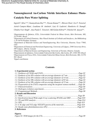
  • 10. S10 Figure S2. TEM images for the Au-CNs nanocomposites. (a), (b) and (c) CN(T)-7-NP; (d), (e) and (f) CN(T)- 14-NP; (g), (h) and (i) CN(T)-65-NR; (j), (l) and (m) CN(T)-15-NR.
  • 11. S11 2.2. 2D WAXS and XRD Synchrotron-based Wide-angle X-ray scattering (WAXS) Synchrotron-based Wide-angle X-ray scattering (WAXS) was employed to investigate the nanocrystalline and stacking features of the materials. The coherent, narrow wavelength, monochromatic synchrotron-based X-ray radiation allows better spectral resolution and peak intensities thus giving insight into the material structural attributes.12–15 The wavelength of BXDS-WLE beamline X-ray radiation was 0.8202 Å which was almost half of the magnitude of CuKα radiation (1.5418 Å) thus a better resolution was accomplished. Since 2θ values are dependent on the incident wavelength thus it is not a valid measure to make a fair comparison. On the other hand, the Q value (Å-1) which is independent of incident X-ray wavelength is an ideal parameter to compare the lattice parameters. So, the Q values (in Å-1) along with the obtained d-spacings are provided to compare the results with existing data. The WAXS 2D map image of the CN displayed two intense diffraction rings due to 100 and 002 plane reflections (Figure S5a).16 The intense 002 plane peak arise due to interplanar stacking of C6N7 constituted conjugated sheets while the (100) peak originated from the periodic in-plane arrangement of C6N7 units. The calculated Q-1 value for 100 and 002 peaks was found to be 0.92 and 1.93 Å-1 corresponding to 6.94 and 3.33 Å d-spacing (Figure S5d). In addition to these main peaks, very faint bands around 3.01 and 3.77 Å-1 were assigned to 300 and 004 planes of melon. Interestingly, these peaks remain obscured in the regular XRD and evidently represent the superiority of synchrotron-based radiation. It should be noted that all these features of carbon nitride were also present in defect-rich CN(T) samples demonstrating the basic carbon nitride scaffold remain intact even after structural defects (Figure S5b and e) The WAXS 2D map and spectra of CN(T)-7-NP exhibited many intense rings/peaks associated with Au gold nanoparticles (Figure S5c and f). Compared to pristine CN and defect-rich CN(T) the peaks corresponding to the carbon nitride framework were relatively weak suggesting that the incorporation of Au followed by ligand removal introduce slight structural deformation.
  • 12. S12 Figure S3. Synchrotron-based WAXS 2D images and obtained Q-1 values of (a) and (d) CN(M); (b) and (e) CN(T); (c) and (f) CN(T)-7-NP, respectively.
  • 13. S13 Figure S4. Fit with Gaussian profiles of Au-CNs nanostructures peaks in the powder X-ray diffractogram at 38.1o, 44.3o, 64.5o and 77.6o, which is attributed to (111), (200), (220) and (311) planes, respectively, of metallic gold (Au0) with cubic structure (JCPDS Card No. 04-0784) of (a), (b), (c) and (d): CN(T)-7-NP; (e), (f), (g) and (h): CN(T)-14-NP; (i), (j), (l) and (m): CN(T)-65-NR; (n), (o), (p) and (q): CN(T)-15-NR. Scherrer equation By the use of the Scherrer equation (Eq. S1) it is possible to describe quantitatively the average size of the crystallites ().17,18 This equation is valid when the crystals are smaller than 0.1µm.19 (Eq. S1) where k is the proportionality constant, which ranges from 0.68 to 2.08. The value used in this equation for the analyzed materials was k = 0.9. Lambda (is the wavelength of the X-
  • 14. S14 rays. For this experiment, a copper tube with an average Kα = 1.54178 Å was used. Beta (is the FWHM, it is obtained by the difference between two extreme values of an independent variable in which it, the function, reaches half of its maximum value. Theta (θ) is the Bragg angle; it is half the peak position on the diffractogram. 2.3. TG and DTG curves Figure S5. TG and DTG curves of Au-CNs synthesized materials performed in a dynamic atmosphere of air synthetic (50 mL min‒1) in an alumina crucible with a heating rate of 10 °C min‒1. 2.4. XPS
  • 15. S15 Figure S6. C 1s, N 1s and Au 4f high-resolution XPS spectra of CN(T)-14-NP, CN(T)-65-NR and CN(T)-15- NR materials. (a), (b) and (c) C 1s high-resolution XPS spectra of CN(T)-14-NP, CN(T)-65-NR and CN(T)- 15-NR materials, respectively. (d), (e) and (f) N 1s high-resolution XPS spectra of CN(T)-14-NP, CN(T)-65- NR and CN(T)-15-NR materials, respectively. (g), (h) and (i) Au 4f high-resolution XPS spectra of CN(T)-14- NP, CN(T)-65-NR and CN(T)-15-NR materials, respectively. 2.5. C K-edge and N K-edge Near Edge X-Ray Absorption Fine Structure (NEXAFS) spectra of the materials
  • 16. S16 To deduce the local electronic environment and coordination state of the materials synchrotron-based near-edge X-ray absorption fine structure (NEXAFS) spectroscopy was performed using soft X-ray at the SGM beamline of Canadian Light Source, Canada. The C-K-edge excitation-emission matrix spectroscopy (EEMS) map of all the samples displayed a sharp emission band around ~285 eV demonstrating an abundance of carbon in all materials (Figure S4a). Figure S4b displays panel carbon K-edge NEXAFS spectra of all the materials. The C K-edge NEXAFS spectra of pristine carbon nitride (CN), defect-rich carbon nitride CN(T) and Au CN(T) nanohybrids exhibited two signature π* resonance peaks located at 284.6 and 287.5 eV.20 The weak resonance peak at 284.6 eV originated due to the π*C=C transition in uncondensed functionalities and carbon adventitious carbons. Another sharp peak at 287.5 eV was attributed to the π*N-C=N transition in N-linked heptazine (C6N7) moieties.21 Interestingly, the pristine CN sample does not have any detectable π*C=C resonance peak while the CN(T) and Au CN(T) displayed a rise of π*C=C signals. The increased π*C=C intensity suggests that defects incorporation in CN structure introduces N deficient sites thus intensifying C=C transitions. Further, the use of organic C-rich ligands during the synthesis step might also contribute to the π*C=C resonance. Furthermore, the high- energy region of C K-edge NEXAFS unveils a broader σ* region originated from sp2 σ*N- C=N and sp3 σ*C-N transitions. The EEMS map of all samples displayed an intense band around ~400 eV attributed to the N K-edge validating N rich character of the materials (Figure S4c) The N K-edge NEXAFS spectra of CN, CN(T) and all other Au-containing samples exhibited two π* resonance peak at 399.3 and 402.2 eV corresponding to π*C–N=C transition of nitrogen in heptazine (C6N7) unit and π*N–C3 of bridging nitrogen (Figure S4d).22,23 Additionally, a broad peak band in the σ* region originated due to sp2 σ*C–N=C and sp3 σ*C–N transitions. The obtained results suggest that despite the presence of plenty of defective states the basic N- linked heptazine framework remains intact.
  • 17. S17 Figure S7. Excitation-Emission Matrix Spectroscopy (EEMS) map of CN(M), CN(T), CN(T)-7-NP, CN(T)- 14-NP, CN(T)-65-NR and CN(T)-15-NR showing (a) C K signal (c) N K signals and corresponding NEXAFS spectra in (b) C K-edge showing π* and σ* transition (d) C K-edge showing π* and σ* resonance peaks. 2.6. Steady-state photoluminescence (PL) The steady-state PL spectra were obtained under an excitation wavelength of 370 nm and showed a peak centered around 450 nm for the synthesized materials (Figure S6a). PL spectra of CN(T) displayed a relatively intense peak compared to CN(M) attributed to enhanced radiative recombination in defect-rich carbon nitride. Previous reports also demonstrate the presence of NH2 defects states promote severe localized recombination.24 Interestingly, after the integration of Au nanostructures, the PL intensity profile of all Au- CN(T) samples was increased which was assumed due to the injection of electrons from Au to CN structure followed by the radiative recombination process. Contradicting TRPL
  • 18. S18 findings, the increased PL intensity suggests in addition to working as an electron sink, Au nanostructures can also pump electrons to the CN scaffold. Considering the fact that NH2 provides intermediate sub-energy, thus more C-Nπ→NH2 σ* electronic transition is taking place in defect-rich carbon nitride. In addition, previous studies suggest that NH2 conjugated with aromatic graphene structure can extend conjugation degree and also delay recombination, leading to better performance.25 Furthermore, Au nanoparticles increased the surface properties of the matrix and improved charge separation by plasmon exciton coupling. Figure S8. (a) Steady-state photoluminescence emission spectra and (b) Time resolved photoluminescence (TRPL) spectra of CN(T)-7-NP and CN(T)-7-NP_300 ºC. Table S1. The PL lifetime decay components and their contribution. The average lifetime (τavg) of each sample Sample (ns) 𝜏1 A1 (ns) 𝜏2 A2 (ns) 𝜏3 A3 R2 (ns) 𝜏𝑎𝑣𝑔 CN(M) 1.21 ± 0.22 0.34 2.75 ± 2.05 0.29 6.9 ± 2.62 0.30 0.9991 5.18 CN(T) 1.26 ± 0.55 0.21 2.77 ± 4.14 0.18 7.96 ± 7.11 0.35 0.9952 6.75 CNT(T)-7-NP 1.06 ± 0.25 0.41 1.88 ± 1.31 0.27 5.53 ± 0.80 0.27 0.9992 3.98 CNT(T)-14-NP 1.06 ± 0.22 0.40 1.91 ± 1.16 0.28 5.47 ± 0.73 0.28 0.9993 3.95 CNT(T)-65-NR 1.14 ± 0.72 0.41 1.64 ± 2.43 0.26 5.27 ± 0.66 0.29 0.9994 3.84 CNT(T)-15-NR 0.92 ± 0.12 0.37 1.86 ± 0.67 0.29 5.10 ± 0.56 0.26 0.9978 3.66 CNT(T)-7-NP_300 ºC 1.04 ± 0.14 0.41 2.24 ± 1.13 0.30 5.94 ± 1.28 0.26 0.9992 4.20 λex: 370 nm, λem: 470 nm, filter: 435 nm; solid state, pure sample.
  • 19. S19 Table S2. EIS fitting parameters and determined components. Sample Condition R1 (Ω) C1 (F) Q2 (F.s^(a-1) a2 R2 (Ω) C2 (F) Dark 8.511 11.93e-9 0.181e-3 0.734 22.3 32.23e-6 CN(M) Light 8.382 12.63e-9 0.133e-3 0.774 22.4 39.21e-6 Dark 7.817 3.86e-9 5.180e-3 0.017 18.0 2.26e-6 CN(T) Light 6.534 11.67e-9 2.870e-3 0.384 20.7 46.81e9 Dark 5.425 3.18e-9 0.189e-3 0.402 116.2 4.07e-6 CN(T)-15-NR Light 4.323 4.27e-9 0.115e-3 0.589 90.46 18.5e-6 Dark 2.012 5.24e-9 0.522e-3 0.999 209.0 28.77e-6 CN(T)-65-NR Light 0.999 3.38e-9 63.89e-6 0.482 121.2 44.34e-6 Dark 1.462 4.01e-9 0.492e-3 0.227 45.0 2.94e-6 CN(T)-14-NP Light 0.821 3.13e-9 0.612e-3 0.356 131.0 4.53e-6 Dark 0.360 3.54e-9 0.123e-3 0.379 109.4 3.38e-6 CN(T)-7-NP Light 0.236 3.39e-9 22.06e-6 0.639 140.3 12.3e-6 Table S3. Comparison of pure water photo-splitting using different catalytic systems Sl. No. Catalyst Light source H2 yield (μmol g-1 h-1) Remarks 1. SWCNT/2D C3N4 heterojunction 300 W Xe lamp 49.8 26 2. Red phosphorous/carbon nitride van der Waals heterostructure (RP-CN) 300 W Xe lamp 367.0 27 3. 3 wt%Pt–3 wt%CoP/g-C3N4 300W Xe lamp 26.25 28 4. Rh-RhOx/PCN (polymeric carbon nitride) 300 W Xe lamp 28 29 5. Boron phosphide@carbon nitride (BP@C3N4) 300 W Xe lamp 31.5 30 6. g-C3.6N4 300 W Xe lamp > 420 nm 75.0 31 7. Three-dimensional porous g-C3N4 nanosheets (3D U-C3N4 NS) 300 W Xe lamp 101.4 32 8. Co(OH)2/C3N4-Cl4/Pt 300 W Xe lamp > 300 nm 48.2 33 9. Ni single atom - PCN (polymeric carbon nitride) 300 W Xe lamp > 420 nm 26.65 34 10. Pt-Co/g-C3N4 300 W Xe lamp > 300 nm 12.2 35 11. LaOCl/PCN (polymeric carbon nitride) 300 W Xe lamp > 300 nm 22.3 36 12. Co-mCN White LED (420 nm < λ < 700 nm) 1.82 37 13. CN(T)-7-NP 300 W Xe, AM1.5G solar simulator 76.8 This work
  • 20. S20 Figure S9. Local density of states of Au13@CN without and with defects (a and b), where blue and red lines indicate the local density of states of CN-p orbits and Au-d orbits, respectively. Their corresponding geometric structures are shown in the insert. Yellow, silver, and grey balls indicate Au, N, and C atoms, respectively.
  • 21. S21 Figure S10. Geometric adsorption structures of H2O* and HO*-H* on the interface with defects (a-b: top views; c-d: side views), interface without defects (e-f), and Au13 cluster (g-h). Yellow, grey, silver, red, and white balls indicate Au, C, N, O, and H atoms, respectively.
  • 22. S22 References 1 I. F. Silva, I. F. Teixeira, R. D. F. Rios, G. M. do Nascimento, I. Binatti, H. F. V. Victória, K. Krambrock, L. A. Cury, A. P. C. Teixeira and H. O. Stumpf, Journal of Hazardous Materials, 2021, 401, 123713. 2 C. A. Simpson, K. J. Salleng, D. E. Cliffel and D. L. Feldheim, Nanomedicine: Nanotechnology, Biology, and Medicine, 2013, 9, 257–263. 3 J. Turkevich, P. C. Stevenson and J. Hillier, Discussions of the Faraday Society, 1951, 11, 55– 75. 4 B. Nikoobakht and M. A. El-Sayed, Chem. Mater., 2003, 15, 1957–1962. 5 U. K. Thakur, A. M. Askar, R. Kisslinger, B. D. Wiltshire, P. Kar and K. Shankar, Nanotechnology, 2017, 28, 274001. 6 A. F. G. Leontowich, A. Gomez, B. D. Moreno, D. Muir, D. Spasyuk, G. King, J. W. Reid, C. Y. Kim and S. Kycia, Journal of Synchrotron Radiation, 2021, 28, 961–969. 7 G. Kresse and J. Furthmuller, Phys. Rev. B: Condens. Matter Mater. Phys., 1996, 54, 11169– 11186. 8 P. E. Blöchl, Phys. Rev. B: Condens. Matter Mater. Phys., 1994, 50, 17953–17979. 9 J. P. Perdew, K. Burke and M. Ernzerhof, Physical Review Letters, 1996, 77, 3865–3868. 10 S. Grimme, J. Antony, S. Ehrlich and H. Krieg, Journal of Chemical Physics, 2010, 132, 154104. 11 W. Tang, E. Sanville and G. Henkelman, Journal of Physics Condensed Matter, 2009, 21, 084204. 12 X. Hu, Z. Zhan, J. Zhang, I. Hussain and B. Tan, Nature Communications, 2021, 12, 1–9. 13 L. Yang, J. R. Tumbleston, H. Zhou, H. Ade and W. You, Energy and Environmental Science, 2013, 6, 316–326. 14 Y. Zhang, Z. Xu, Q. Wang, W. Hao, X. Zhai, X. Fei, X. Huang and Y. Bi, Applied Catalysis B: Environmental, 2021, 299, 120679. 15 X. Wang, K. Klingan, I. Martens, A. Bagger, M. Klingenhof, T. Möller, J. F. De Araújo, S. Jiang, J. Rossmeisl, H. Dau and P. Strasser, Nature Communications, 2021, 12, 1–12. 16 J. W. Wang, M. Gil-Sepulcre, H. H. Huang, E. Solano, Y. F. Mu, A. Llobet and G. Ouyang, Cell Reports Physical Science, 2021, 2, 100681. 17 C. F. Holder and R. E. Schaak, ACS Nano, 2019, 13, 7359–7365. 18 H. Borchert, E. V. Shevchenko, A. Robert, I. Mekis, A. Kornowski, G. Grübel and H. Weller, Langmuir, 2005, 21, 1931–1936. 19 A. Monshi, M. R. Foroughi and M. R. Monshi, World Journal of Nano Science and Engineering, 2012, 2, 154–160. 20 N. Meng, W. Zhou, Y. Yu, Y. Liu and B. Zhang, ACS Catalysis, 2019, 9, 10983–10989. 21 Y. Xu, C. Qiu, X. Fan, Y. Xiao, G. Zhang, K. Yu, H. Ju, X. Ling, Y. Zhu and C. Su, Applied Catalysis B: Environmental, 2020, 268, 118457. 22 J. Zhang, Y. Li, X. Zhao, L. Wang, H. Chen, S. Wang, X. Xu, L. Shi, L. C. Zhang, Y. Zhu, H. Zhang, Y. Liu, G. Nealon, S. Zhang, M. Wu, S. Wang and H. Sun, Nano Energy, 2021, 89, 106357. 23 Y. Zheng, Y. Jiao, Y. Zhu, L. H. Li, Y. Han, Y. Chen, A. Du, M. Jaroniec and S. Z. Qiao, Nature Communications, 2014, 5, 3783. 24 Y. Zhang, Q. Pan, G. Chai, M. Liang, G. Dong, Q. Zhang and J. Qiu, Scientific Reports, 2013, 3, 1–8. 25 L. C. Chen, C. Y. Teng, C. Y. Lin, H. Y. Chang, S. J. Chen and H. Teng, Advanced Energy Materials, 2016, 6, 1600719. 26 S. Wang, L. Chen, X. Zhao, J. Zhang, Z. Ao, W. Liu, H. Wu, L. Shi, Y. Yin, X. Xu, C. Zhao and X. Duan, Applied Catalysis B: Environmental, 2020, 278, 119312.
  • 23. S23 27 M. Wang, Z. Qin, Z. Diao, R. Li, J. Zhong and Y. Chen, ACS Sustainable Chemistry & Engineering, 2020, 8, 13459–13466. 28 Z. Pan, Y. Zheng, F. Guo, P. Niu and X. Wang, ChemSusChem, 2017, 10, 87–90. 29 Z. Pan, S. Wang, P. Niu, M. Liu and X. Wang, Journal of Catalysis, 2019, 379, 129–137. 30 B. Tian, Y. Wu and G. Lu, Applied Catalysis B: Environmental, 2021, 280, 119410. 31 H. Liu, M. Shen, P. Zhou, Z. Guo, X. Liu, W. Yang, M. Gao, M. Chen, H. Guan, N. P. Padture, Y. Yu, S. Guo and S. Sun, Nanoscale, 2021, 13, 9315–9321. 32 X. Chen, R. Shi, Q. Chen, Z. Zhang, W. Jiang, Y. Zhu and T. Zhang, Nano Energy, 2019, 59, 644–650. 33 Q. Zhang, X. Chen, Z. Yang, T. Yu, L. Liu and J. Ye, ACS Applied Materials and Interfaces, 2022, 14, 3970–3979. 34 Y. Li, Y. Wang, C. L. Dong, Y. C. Huang, J. Chen, Z. Zhang, F. Meng, Q. Zhang, Y. Huangfu, D. Zhao, L. Gu and S. Shen, Chemical Science, 2021, 12, 3633–3643. 35 G. Zhang, Z. A. Lan, L. Lin, S. Lin and X. Wang, Chemical Science, 2016, 7, 3062–3066. 36 Y. Lin, W. Su, X. Wang, X. Fu and X. Wang, Angewandte Chemie - International Edition, 2020, 59, 20919–20923. 37 Y. Dou, C. Zhu, M. Zhu, Y. Fu, H. Wang, C. Shi, H. Huang, Y. Liu and Z. Kang, Applied Surface Science, 2020, 509, 144706.