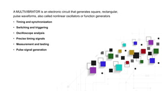
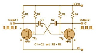
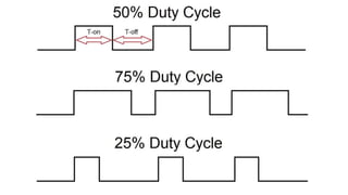
Multivibrators
circuit
Muhammad Ahmad
Muqadass Tahir
Abdullahannan
A MULTIVIBRATOR is an electronic circuit that generates square, rectangular,
pulse waveforms, also called nonlinear oscillators or function generators
• Timing and synchronization
• Switching and triggering
• Oscilloscope analysis
• Precise timing signals
• Measurement and testing
• Pulse signal generation
History  Communication was done through Telrgraphs,radio
signal, & signal lamps
 Developed during world war 1 by Abrahim and Bloch
 Paper Published in 1919 AD
Types of
Multivibrators
Astable Multivibrator
Monostable Multivibrator
Bistable Multivibrator
Astable Multivibrator
• Oscillation: Alternates between
"HIGH" and "LOW" states.
• "HIGH" state activates the buzzer,
"LOW" state silences it.
• Frequency: Adjustable using resistors
and capacitors
Example: Buzzer Tone Generator
• Alternates between "HIGH" and "LOW" states.
• Oscillation Frequency: Adjustable by modifying resistors and capacitors
• Applications: Used in alarms, electronic toys, and sound effects generators.
Monostable multivibrator
• One stable state and one unstable state
• Transition from stable to unstable state
upon trigger
• Generates a single pulse of a specific
duration
Capacitive Touch Sensor
• Touching the sensor generates a trigger signal.
• Action: Unstable state activates an output (e.g., LED, sound)
• Stable State: Circuit automatically returns to stable state.
Bistable Multivibrator
• Two stable states, remains in each state until
triggered.
• Once triggered, remains in the new state until
triggered again.
• Often synchronized with a clock signal for
controlled state transitions.
• Provides stable output even in the absence of
a triggering signal.
Garage Door Opener Circuit
• Stable States: "Open" and "Closed" states for the garage door
• Remote control signal transitions between states
• State Retention: Circuit maintains the current state until triggered again.
Applications of
Multivibrators
Muqadass Tahir
0033
Multivibrators have
diverse applications
in electronics
Timing and Clock
Generation
Provide accurate and
stable clock signals
for digital systems.
Pulse and Waveform
Generation
Generate square
waves and pulses for
signal processing and
modulation.
Digital Logic and
Memory Elements
Serve as memory
elements in digital
circuits for data
storage.
Frequency Division
and Counting
Used in frequency
division and counting
applications.
Timing Circuits
Timing circuits are vital in electronic systems for generating precise
timing signals and controlling the sequencing of operations
Simple Example: Traffic Light System
• Timing circuits control traffic lights for safe and efficient traffic flow.
• They generate precise timing signals for each phase of the traffic lights.
• Timing circuits allow adjustments in frequency and duration of each signal phase.
• They introduce delays between signal transitions for safe intersection clearing.
Frequency Division
Frequency dividers, allowing the division of an input frequency into
lower-frequency outputs
Simple Example: Frequency Division in a Digital Watch
• Digital watches use frequency division to display accurate time.
• A quartz oscillator generates a high-frequency signal.
• A frequency divider circuit divides the signal to a lower frequency.
• The divided signal drives the watch's timekeeping mechanism.
• This technique ensures precise timekeeping and display synchronization
Pulse Generation
Pulse generation in multivibrators refers to the creation of pulses with
specific characteristics, such as duration, frequency, and shape.
Simple Example: Blinking LED Circuit
• A blinking LED circuit is an example of pulse generation using multivibrators.
• The circuit uses an astable multivibrator configuration with two transistors or gates.
• The multivibrator switches between two states, turning the LED on and off.
• The timing components control the duration of each state, creating the blinking effect.
• This circuit is commonly used for visual indicators or decorative lighting.
Advantages &
Disadvantages
Abdullhannan Mirza
0018
Advantages
• Improved reliability and stability
• Flexibility in designing complex
timing functions
• Easy integration with other circuit
elements
• Lower power consumption
compared to alternative solutions
e.g.,
"Electronic Fuel injection in modern cars"
• Multivibrators used for precise timing control in fuel injection
• Ensure reliable engine performance and improved fuel efficiency
• Flexibility in adapting timing functions to different engine conditions
• Easy integration with other system components
• Lower power consumption compared to alternatives
• Contribute to optimized overall performance and efficiency.
But..
Limitations
• Sensitivity to component
tolerances and variations
• Challenges in achieving high-
frequency operation
• Impact of temperature variations
on multivibrator performance
• Limited output power capabilities
• Noise susceptibility in certain
configurations
LED (Light-Emitting Diode)
• Sensitivity to voltage fluctuations,
addressed with voltage regulation
techniques
• Thermal management challenges,
requiring effective heat dissipation
• Color consistency achieved through
calibration and LED selection
• Integration with lighting controls for
customizable lighting options
• Ongoing efficiency improvements for
energy-saving benefits
Multivibrators.pptx

Multivibrators.pptx

  • 1.
  • 2.
    A MULTIVIBRATOR isan electronic circuit that generates square, rectangular, pulse waveforms, also called nonlinear oscillators or function generators • Timing and synchronization • Switching and triggering • Oscilloscope analysis • Precise timing signals • Measurement and testing • Pulse signal generation
  • 4.
    History  Communicationwas done through Telrgraphs,radio signal, & signal lamps  Developed during world war 1 by Abrahim and Bloch  Paper Published in 1919 AD
  • 5.
  • 6.
    Astable Multivibrator • Oscillation:Alternates between "HIGH" and "LOW" states. • "HIGH" state activates the buzzer, "LOW" state silences it. • Frequency: Adjustable using resistors and capacitors
  • 8.
    Example: Buzzer ToneGenerator • Alternates between "HIGH" and "LOW" states. • Oscillation Frequency: Adjustable by modifying resistors and capacitors • Applications: Used in alarms, electronic toys, and sound effects generators.
  • 9.
    Monostable multivibrator • Onestable state and one unstable state • Transition from stable to unstable state upon trigger • Generates a single pulse of a specific duration
  • 10.
    Capacitive Touch Sensor •Touching the sensor generates a trigger signal. • Action: Unstable state activates an output (e.g., LED, sound) • Stable State: Circuit automatically returns to stable state.
  • 11.
    Bistable Multivibrator • Twostable states, remains in each state until triggered. • Once triggered, remains in the new state until triggered again. • Often synchronized with a clock signal for controlled state transitions. • Provides stable output even in the absence of a triggering signal.
  • 12.
    Garage Door OpenerCircuit • Stable States: "Open" and "Closed" states for the garage door • Remote control signal transitions between states • State Retention: Circuit maintains the current state until triggered again.
  • 13.
  • 14.
    Multivibrators have diverse applications inelectronics Timing and Clock Generation Provide accurate and stable clock signals for digital systems. Pulse and Waveform Generation Generate square waves and pulses for signal processing and modulation. Digital Logic and Memory Elements Serve as memory elements in digital circuits for data storage. Frequency Division and Counting Used in frequency division and counting applications.
  • 15.
    Timing Circuits Timing circuitsare vital in electronic systems for generating precise timing signals and controlling the sequencing of operations Simple Example: Traffic Light System • Timing circuits control traffic lights for safe and efficient traffic flow. • They generate precise timing signals for each phase of the traffic lights. • Timing circuits allow adjustments in frequency and duration of each signal phase. • They introduce delays between signal transitions for safe intersection clearing.
  • 16.
    Frequency Division Frequency dividers,allowing the division of an input frequency into lower-frequency outputs Simple Example: Frequency Division in a Digital Watch • Digital watches use frequency division to display accurate time. • A quartz oscillator generates a high-frequency signal. • A frequency divider circuit divides the signal to a lower frequency. • The divided signal drives the watch's timekeeping mechanism. • This technique ensures precise timekeeping and display synchronization
  • 17.
    Pulse Generation Pulse generationin multivibrators refers to the creation of pulses with specific characteristics, such as duration, frequency, and shape. Simple Example: Blinking LED Circuit • A blinking LED circuit is an example of pulse generation using multivibrators. • The circuit uses an astable multivibrator configuration with two transistors or gates. • The multivibrator switches between two states, turning the LED on and off. • The timing components control the duration of each state, creating the blinking effect. • This circuit is commonly used for visual indicators or decorative lighting.
  • 18.
  • 19.
    Advantages • Improved reliabilityand stability • Flexibility in designing complex timing functions • Easy integration with other circuit elements • Lower power consumption compared to alternative solutions
  • 20.
    e.g., "Electronic Fuel injectionin modern cars" • Multivibrators used for precise timing control in fuel injection • Ensure reliable engine performance and improved fuel efficiency • Flexibility in adapting timing functions to different engine conditions • Easy integration with other system components • Lower power consumption compared to alternatives • Contribute to optimized overall performance and efficiency.
  • 21.
  • 22.
    Limitations • Sensitivity tocomponent tolerances and variations • Challenges in achieving high- frequency operation • Impact of temperature variations on multivibrator performance • Limited output power capabilities • Noise susceptibility in certain configurations
  • 23.
    LED (Light-Emitting Diode) •Sensitivity to voltage fluctuations, addressed with voltage regulation techniques • Thermal management challenges, requiring effective heat dissipation • Color consistency achieved through calibration and LED selection • Integration with lighting controls for customizable lighting options • Ongoing efficiency improvements for energy-saving benefits

Editor's Notes

  • #20 Compability with digital logic circuits Ability to generate precise and stable waveforms  Versatility in circuit design and customization