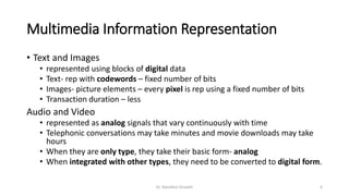
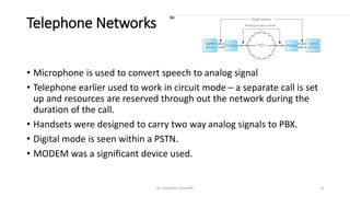
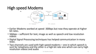
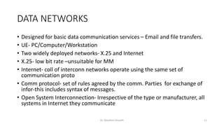
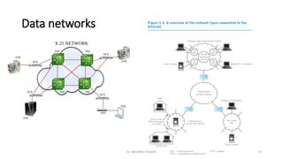
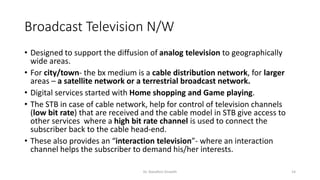
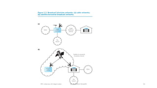
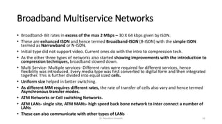
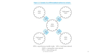
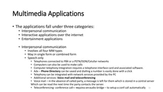
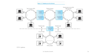
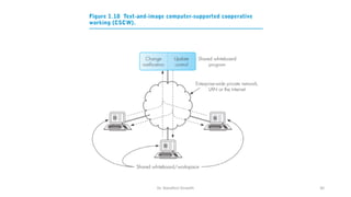
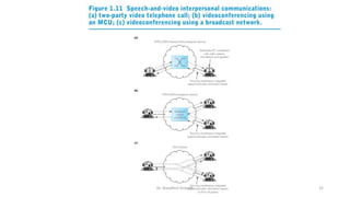
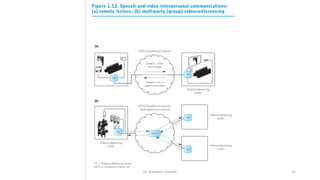
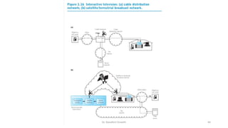
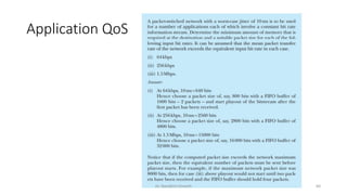
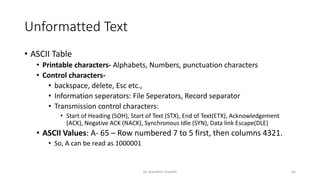
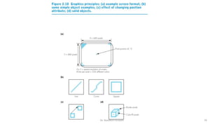
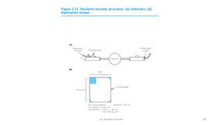
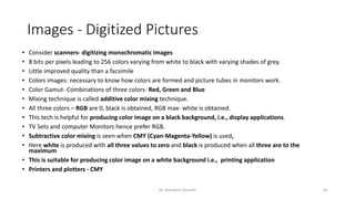
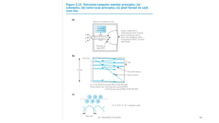
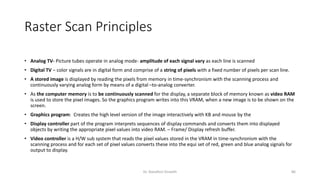
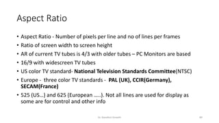
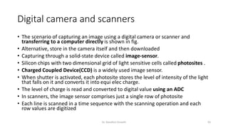
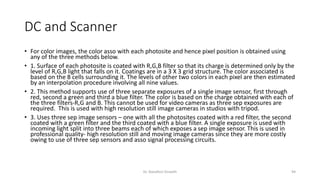
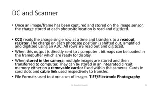
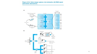
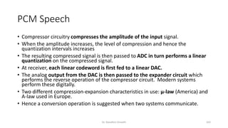
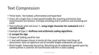
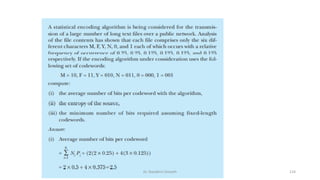
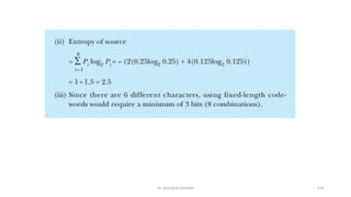
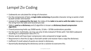
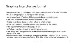
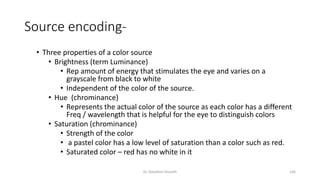
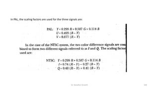
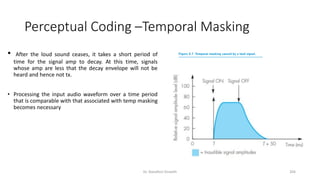
The document discusses different types of multimedia and applications. It describes how text, images, audio and video can be represented digitally and transmitted over networks. It covers various network types used for multimedia communication, including telephone networks, data networks, broadcast television networks, integrated services digital networks, and broadband multiservice networks. Applications of multimedia include interpersonal communication, interactive applications over the internet, and entertainment applications like video calls, video conferencing, voice mail and internet telephony.

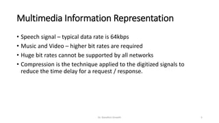


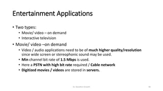
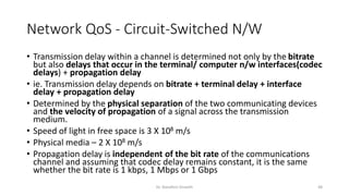
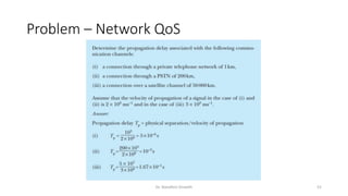
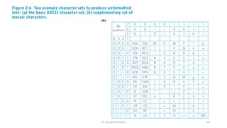
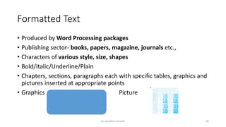
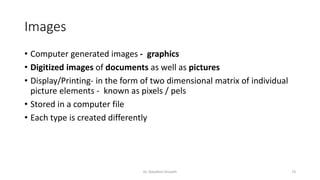

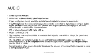


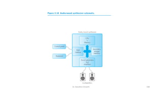
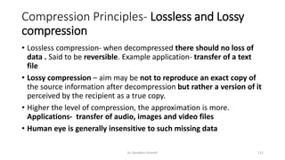
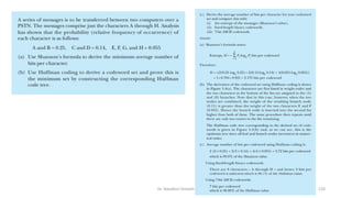

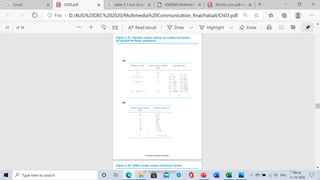
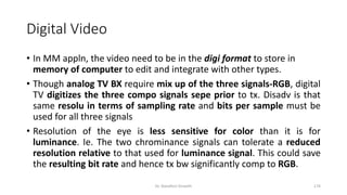
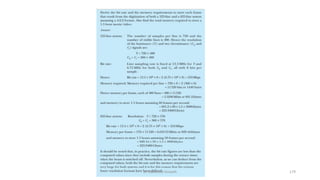
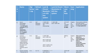
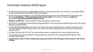
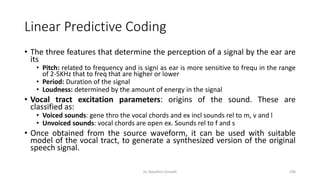
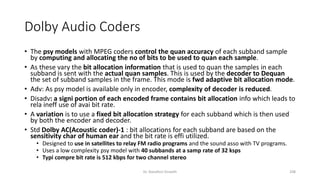
![Two dimensional code table contents
Mode Runlength to e encoded Abbreviation Codeword
Pass b1b2 P 0001+b1b2
Horizontal a0a1,a1a2 H 001+a0a1+a1a2
Vertical a1b1=0
a1b1=-1
a1b1=-2
a1b1=-3
a1b1=+1
a1b1=+2
a1b1=+3
V[0]
VR[1]
VR [2]
VR [3]
VL [1]
VL [2]
VL [3]
1
011
000011
0000011
010
000010
0000010
Extension 0000001000
Dr. Nandhini Vineeth 140](https://image.slidesharecdn.com/mmc-allunits-240302122530-0b37fcb2/85/Multimedia-communication-notes-for-engineers-pdf-140-320.jpg)
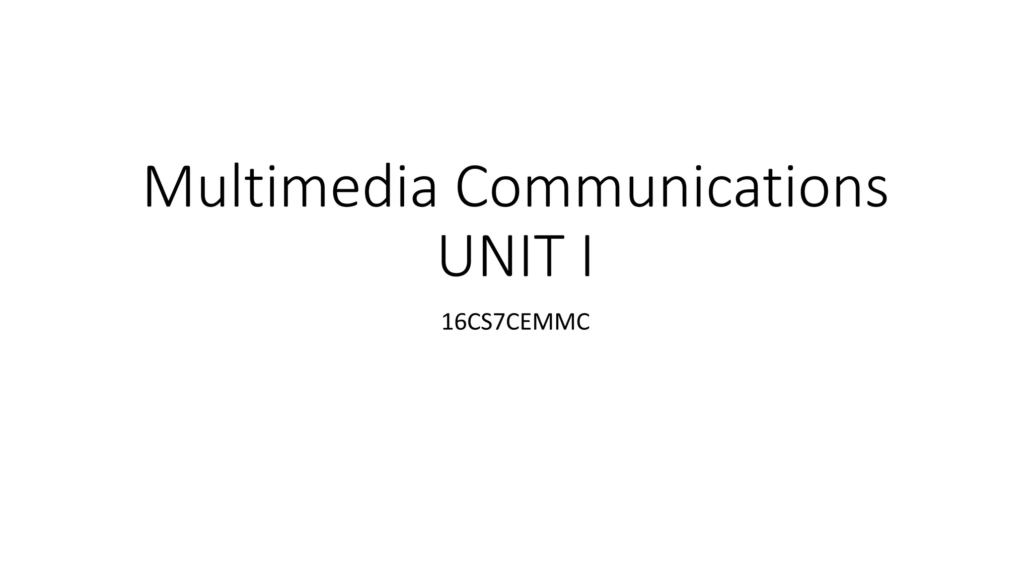
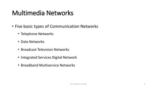
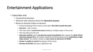
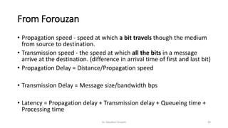
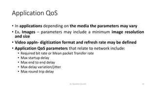
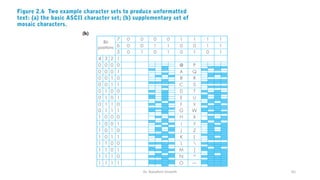
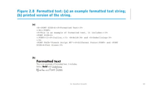
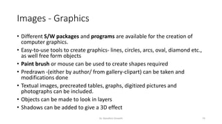
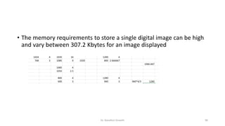
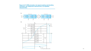
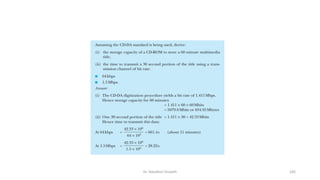
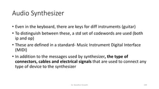
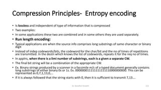
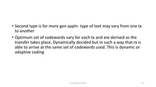
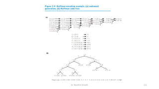
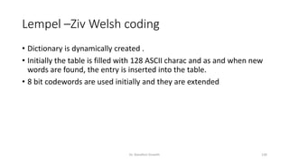
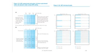
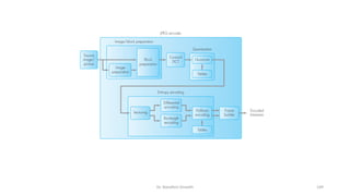
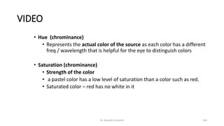
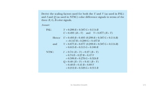
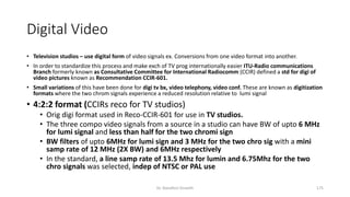
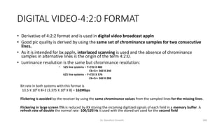
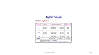
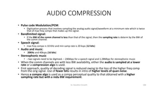
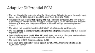
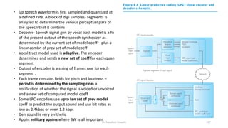
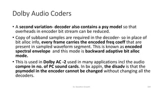
![Joint Photographic Experts Group
• JPEG is defined in the international std IS 10918
• A range of different compression modes according to the appln is chosen
• Discussion is on lossy sequential mode/baseline mode – as it is used for both monochromatic and
color digitized images
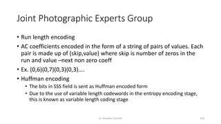
• 5 Stages as in figure
• Image/Block preparation
• Inp – Mono chrome, CLUT, RGB, YCbCr
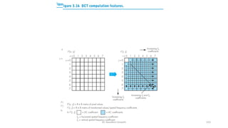
• As DCT is involved and every pixel calculation involves all the pixels in the image, first 8 X 8 blocks
are constructed.
• Formula used for the conversion of 2D input matrix P[x,y] to the transformed matrix F[i,j]
• x,y,i and j vary from 0 to 7
Dr. Nandhini Vineeth 148](https://image.slidesharecdn.com/mmc-allunits-240302122530-0b37fcb2/85/Multimedia-communication-notes-for-engineers-pdf-148-320.jpg)
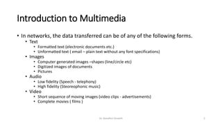
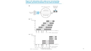
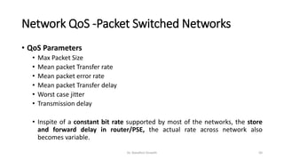
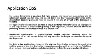
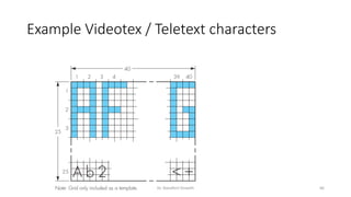
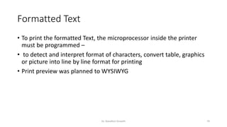
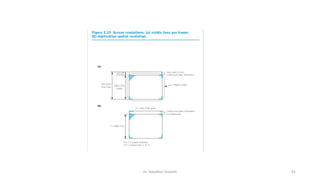
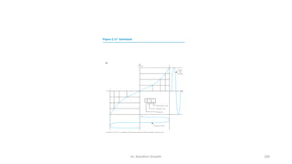
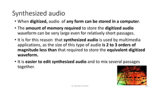
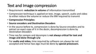
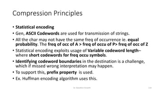
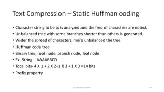
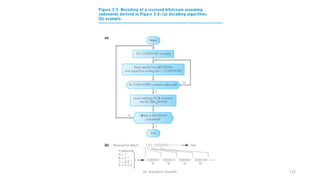
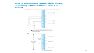
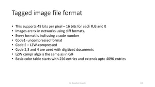
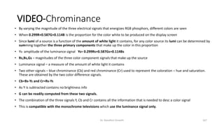
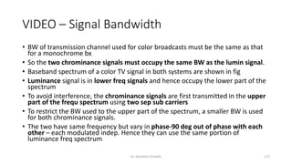
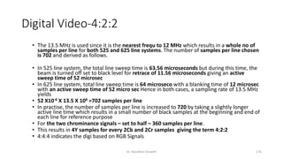
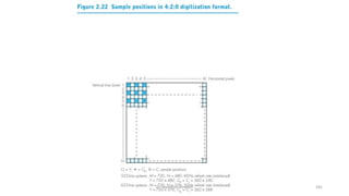
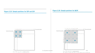
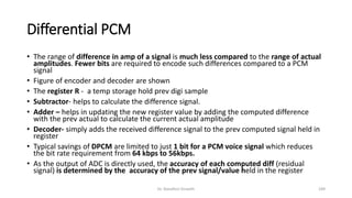
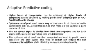
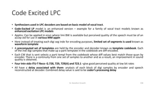
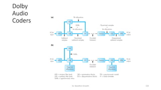
![Joint Photographic Experts Group
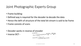
• All 64 values in input matrix contri to each entry in the transformed matrix
• When i=0 and j=0, the hori and verti freq coeff- two cosines terms become 1 and
hence F[0,0] deals simply a summation of all values in the input matrix.
Essentially it is the mean of all 64 values and known as DC coefficient
• All other have a freq cooeff assoc either hori or verti – these are known as AC
coefficients
• For j=0, only hori freq coeff are present
• For i=0, only verti freq coeff are present
• In all transformed matrix, both horiz and verti freq coeff are present to varying
degrees
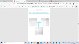
• When a single color is seen, the DC Coeff is the same and only a few AC coeff
within them.
• Color transitions show diff DC coeff and a larger number of AC coeff in them
Dr. Nandhini Vineeth 151](https://image.slidesharecdn.com/mmc-allunits-240302122530-0b37fcb2/85/Multimedia-communication-notes-for-engineers-pdf-151-320.jpg)


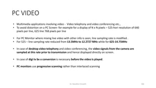


![PPT Multimedia_Communications (1)[1].pdf](https://cdn.slidesharecdn.com/ss_thumbnails/pptmultimediacommunications11-250227022007-06c7636d-thumbnail.jpg?width=640&height=640&fit=bounds)