SlideShare a Scribd company logo
Motion Capture System
(MO-CAP)
Presented to:
Prof. Aboul Ella Hassan
Student name:
Alaa Mohamed Saeed
May 3, 2017
© 2017 Alaa Mohamed All Rights Reserved
Contents
1. Introduction
2. Optical systems
2.1. Passive markers
2.2. Active markers
3. Non-optical systems
3.1. Inertial systems
3.2. Mechanical motion
3.3. Magnetic systems
4. Conclusions
5. References
Motion Capture Process and Systems
Figure (1)
Abstract
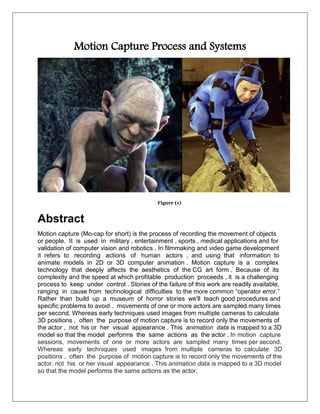
Motion capture (Mo-cap for short) is the process of recording the movement of objects
or people. It is used in military , entertainment , sports , medical applications and for
validation of computer vision and robotics . In filmmaking and video game development
it refers to recording actions of human actors , and using that information to
animate models in 2D or 3D computer animation . Motion capture is a complex
technology that deeply affects the aesthetics of the CG art form . Because of its
complexity and the speed at which profitable production proceeds , it is a challenging
process to keep under control . Stories of the failure of this work are readily available,
ranging in cause from technological difficulties to the more common “operator error.”
Rather than build up a museum of horror stories we'll teach good procedures and
specific problems to avoid . movements of one or more actors are sampled many times
per second. Whereas early techniques used images from multiple cameras to calculate
3D positions , often the purpose of motion capture is to record only the movements of
the actor , not his or her visual appearance . This animation data is mapped to a 3D
model so that the model performs the same actions as the actor . In motion capture
sessions, movements of one or more actors are sampled many times per second.
Whereas early techniques used images from multiple cameras to calculate 3D
positions , often the purpose of motion capture is to record only the movements of the
actor, not his or her visual appearance . This animation data is mapped to a 3D model
so that the model performs the same actions as the actor.
Figure (2)
1: Introduction
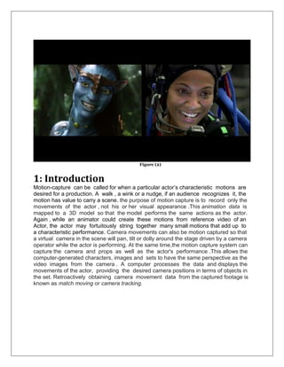
Motion-capture can be called for when a particular actor’s characteristic motions are
desired for a production. A walk , a wink or a nudge, if an audience recognizes it, the
motion has value to carry a scene. the purpose of motion capture is to record only the
movements of the actor , not his or her visual appearance .This animation data is
mapped to a 3D model so that the model performs the same actions as the actor.
Again , while an animator could create these motions from reference video of an
Actor, the actor may fortuitously string together many small motions that add up to
a characteristic performance. Camera movements can also be motion captured so that
a virtual camera in the scene will pan, tilt or dolly around the stage driven by a camera
operator while the actor is performing. At the same time,the motion capture system can
capture the camera and props as well as the actor's performance .This allows the
computer-generated characters, images and sets to have the same perspective as the
video images from the camera . A computer processes the data and displays the
movements of the actor, providing the desired camera positions in terms of objects in
the set. Retroactively obtaining camera movement data from the captured footage is
known as match moving or camera tracking.
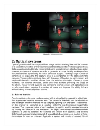
Figure (3) Silhouette tracking
2: Optical systems
Optical systems utilize data captured from image sensors to triangulate the 3D position
of a subject between two or more cameras calibrated to provide overlapping projections.
Data acquisition is traditionally implemented using special markers attached to an actor;
however, more recent systems are able to generate accurate data by tracking surface
features identified dynamically for each particular subject. Tracking a large number of
performers or expanding the capture area is accomplished by the addition of more
cameras. These systems produce data with 3 degrees of freedom for each marker, and
rotational information must be inferred from the relative orientation of three or more
markers ; for instance shoulder , elbow and wrist markers providing the angle of
the elbow. Newer hybrid systems are combining inertial sensors with optical sensors
to reduce occlusion , increase the number of users and improve the ability to track
without having to manually clean up data.
2.1 Passive markers
Passive optical system use markers coated with a retroreflective material to reflect light
that is generated near the cameras lens. The camera's threshold can be adjusted so
only the bright reflective markers will be sampled, ignoring skin and fabric .The centroid
of the marker is estimated as a position within the two-dimensional image that is
captured. The grayscale value of each pixel can be used to provide sub-pixel accuracy
by finding the centroid of the Gaussian . An object with markers attached at known
positions is used to calibrate the cameras and obtain their positions and the lens
distortion of each camera is measured. If two calibrated cameras see a marker, a three-
dimensional fix can be obtained . Typically a system will consist of around 2 to 48
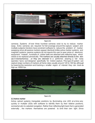
Figure (4)
cameras . Systems of over three hundred cameras exist to try to reduce marker
swap. Extra cameras are required for full coverage around the capture subject and
multiple subjects.Vendors have constraint software to reduce the problem of marker
swapping since all passive markers appear identical.Unlike active marker systems and
magnetic systems, passive systems do not require the user to wear wires or electronic
equipment . Instead , hundreds of rubber balls are attached with reflective tape, which
needs to be replaced periodically. The markers are usually attached directly to the skin
(as in biomechanics) , or they are velcroed to a performer wearing a full body
spandex / lycra suit designed specifically for motion capture. This type of system can
capture large numbers of markers at frame rates usually around 120 to 160 fps although
by lowering the resolution and tracking a smaller region of interest they can track as
high as 10000 fps.
Figure (5)
2.2 Active marker
Active optical systems triangulate positions by illuminating one LED at a time very
quickly or multiple LEDs with software to identify them by their relative positions,
somewhat akin to celestial navigation. Rather than reflecting light back that is generated
externally , the markers themselves are powered to emit their own light . Since
Inverse Square law provides 1/4 the power at 2 times the distance, this can increase
the distances and volume for capture. This also enables high signal-to-noise ratio,
resulting in very low marker jitter and a resulting high measurement resolution
(often down to 0.1 mm within the calibrated volume).
3: Non-optical systems
3.1 Inertial systems
Inertial Motion Capture technology is based on miniature inertial sensors biomechanical
models and sensor fusion algorithms. The motion data of the inertial sensors (inertial
guidance system ) is often transmitted wirelessly to a computer, where the motion is
recorded or viewed . Most inertial systems use inertial measurement units (IMUs)
containing a combination of gyroscope, magnetometer, and accelerometer, to measure
rotational rates . These rotations are translated to a skeleton in the software. Much like
optical markers, the more IMU sensors the more natural the data. No external cameras,
emitters or markers are needed for relative motions, although they are required to give
the absolute position of the user if desired. Inertial motion capture systems capture the
full six degrees of freedom body motion of a human in real-time and can give limited
direction information if they include a magnetic bearing sensor , although these are
much lower resolution and susceptible to electromagnetic noise . Benefits of using
Inertial systems include : capturing in a variety of environments including tight spaces,
no solving, portability, and large capture areas. Disadvantages include lower positional
accuracy and positional drift which can compound over time . These systems are
similar to the Wii controllers but are more sensitive and have greater resolution and
update rates. They can accurately measure the direction to the ground to within a
degree . The popularity of inertial systems is rising amongst independent game
developers , mainly because of the quick and easy set up resulting in a fast pipeline. A
range of suits are now available from various manufacturers and base prices range from
$1,000 to $80,000 USD.
3.2 Mechanical motion
Mechanical motion capture systems directly track body joint angles and are often
referred to as exoskeleton motion capture systems , due to the way the sensors are
attached to the body . A performer attaches the skeletal-like structure to their body
and as they move so do the articulated mechanical parts, measuring the performer’s
relative motion . Mechanical motion capture systems are real-time, relatively low-cost,
free-of-occlusion , and wireless (untethered) systems that have unlimited capture
volume. Typically, they are rigid structures of jointed, straight metal or plastic rods linked
together with potentiometers that articulate at the joints of the body. These suits tend to
be in the $25,000 to $75,000 range plus an external absolute positioning system. Some
suits provide limited force feedback or haptic input.
3.3 Magnetic systems
Magnetic systems calculate position and orientation by the relative magnetic flux of
three orthogonal coils on both the transmitter and each receiver. The relative intensity of
the voltage or current of the three coils allows these systems to calculate both
range and orientation by meticulously mapping the tracking volume. The sensor output
is 6DOF , which provides useful results obtained with two-thirds the number of markers
required in optical systems; one on upper arm and one on lower arm for elbow position
and angle .The markers are not occluded by nonmetallic objects but are susceptible
to magnetic and electrical interference from metal objects in the environment , like
rebar (steel reinforcing bars in concrete) or wiring, which affect the magnetic field, and
electrical sources such as monitors, lights, cables and computers. The sensor response
is nonlinear , especially toward edges of the capture area. The wiring from the sensors
tends to preclude extreme performance movements . With magnetic systems , it is
possible to monitor the results of a motion capture session in real time .The capture
volumes for magnetic systems are dramatically smaller than they are for optical
systems. With the magnetic systems , there is a distinction between “AC” and “DC”
systems: one uses square pulses, the other uses sine wave pulse.
4: Related techniques
4.1 Facial motion capture
Most traditional motion capture hardware vendors provide for some type of low
resolution facial capture utilizing anywhere from 32 to 300 markers with either an active
or passive marker system. All of these solutions are limited by the time it takes to apply
the markers, calibrate the positions and process the data.Ultimately the technology also
limits their resolution and raw output quality levels. High fidelity facial motion capture,
also known as performance capture, is the next generation of fidelity and is utilized to
record the more complex movements in a human face in order to capture higher
degrees of emotion. Facial capture is currently arranging itself in several distinct camps,
including traditional motion capture data, blend shaped based solutions, capturing the
actual topology of an actor's face, and proprietary systems . The two main techniques
are stationary systems with an array of cameas capturing the facial expressions from
multiple an gles and using software such as the stereo mesh solver from OpenCV to
create a 3D surface mesh, or to use light arrays as well to calculate the surface normals
from the variance in brightness as the light source , camera position or both are
changed. These techniques tend to be only limited in feature resolution by the camera
resolution, apparent object size and number of cameras. If the users face is 50 percent
of the working area of the camera and a camera has megapixel resolution, then sub
millimeter facial motions can be detected by comparing frames. Recent work is focusing
on increasing the frame rates and doing optical flow to allow the motions to b retargeted
Figure (6) capturing gesture and facial expression
to other computer generated faces, rather than just making a 3D Mesh of the actor and
their expressions.
4.2 RF positioning
RF ( radio frequency ) positioning systems are becoming more viable as higher
frequency RF devices allow greater precision than older RF technologies such as
traditional radar . The speed of light is 30 centimeters per nanosecond (billionth of a
second), so a 10 gigahertz (billion cycles per second) RF signal enables an accuracy of
about 3 centimeters. By measuring amplitude to a quarter wavelength , it is possible to
improve the resolution down to about 8 mm. To achieve the resolution of optical
systems, frequencies of 50 gigahertz or higher are needed , which are almost as line
of sight and as easy to block as optical systems. Multipath and reradiation of the signal
are likely to cause additional problems , but these technologies will be ideal for
tracking larger volumes with reasonable accuracy, since the required resolution at 100
meter distances is not likely to be as high . Many RF scientists believe that radio
frequency will never produce the accuracy required for motion capture.
5: Conclusions
Motion capture (MO-Cap) is a way to digitally record human movements. The recorded
motion capture data is mapped on a digital model in 3D software (e.g. Unreal Engine,
Unity 3D, Maya or 3D Studio Max) so the digital character moves like the actor you
recorded. The Mo-Cap technology is used in the entertainment industry for films and
games to get more realistic human movements.
6:References
https://en.wikipedia.org/wiki/Motion_capture
http://optitrack.com/
https://www.xsens.com/tags/motion-capture/
https://www.vicon.com/what-is-motion-capture
https://en.wikipedia.org/wiki/Motion_capture
http://www.cs.cmu.edu/~jkh/video_games/mocap.pdf
https://sagarlonkar.com/about-2/motion-capture/types-ofmotion-capture/
https://en.wikipedia.org/wiki/Rotoscoping
https://lukebeech.wordpress.com/motion-capture/
.

More Related Content

What's hot

ShawnQuinnCSS565FinalResearchProject
ShawnQuinnCSS565FinalResearchProjectShawnQuinnCSS565FinalResearchProject
ShawnQuinnCSS565FinalResearchProject
Shawn Quinn
 
Multi Inertial Measurement Units (MIMU) Platforms: Designs & Applications
Multi Inertial Measurement Units (MIMU)  Platforms: Designs & ApplicationsMulti Inertial Measurement Units (MIMU)  Platforms: Designs & Applications
Multi Inertial Measurement Units (MIMU) Platforms: Designs & Applications
oblu.io
 
A biologically inspired cmos image sensor
A biologically inspired cmos image sensorA biologically inspired cmos image sensor
A biologically inspired cmos image sensor
Springer
 

What's hot (16)

Advantages and Disadvantages of Motion Capture
Advantages and Disadvantages of Motion CaptureAdvantages and Disadvantages of Motion Capture
Advantages and Disadvantages of Motion Capture
 
ShawnQuinnCSS565FinalResearchProject
ShawnQuinnCSS565FinalResearchProjectShawnQuinnCSS565FinalResearchProject
ShawnQuinnCSS565FinalResearchProject
 
Multi Inertial Measurement Units (MIMU) Platforms: Designs & Applications
Multi Inertial Measurement Units (MIMU)  Platforms: Designs & ApplicationsMulti Inertial Measurement Units (MIMU)  Platforms: Designs & Applications
Multi Inertial Measurement Units (MIMU) Platforms: Designs & Applications
 
A biologically inspired cmos image sensor
A biologically inspired cmos image sensorA biologically inspired cmos image sensor
A biologically inspired cmos image sensor
 
IRJET- A Survey on Control of Mechanical ARM based on Hand Gesture Recognitio...
IRJET- A Survey on Control of Mechanical ARM based on Hand Gesture Recognitio...IRJET- A Survey on Control of Mechanical ARM based on Hand Gesture Recognitio...
IRJET- A Survey on Control of Mechanical ARM based on Hand Gesture Recognitio...
 
Motion Capture
Motion CaptureMotion Capture
Motion Capture
 
Gesture Controlled Wheelchair With Stretcher
Gesture Controlled Wheelchair With StretcherGesture Controlled Wheelchair With Stretcher
Gesture Controlled Wheelchair With Stretcher
 
Optimization of Average Distance Based Self-Relocation Algorithm Using Augmen...
Optimization of Average Distance Based Self-Relocation Algorithm Using Augmen...Optimization of Average Distance Based Self-Relocation Algorithm Using Augmen...
Optimization of Average Distance Based Self-Relocation Algorithm Using Augmen...
 
Automation of Wheelchair Using Iris Movement
Automation of Wheelchair Using Iris MovementAutomation of Wheelchair Using Iris Movement
Automation of Wheelchair Using Iris Movement
 
Osmium MIMU22BT: A Micro Wireless Multi-IMU (MIMU) Inertial Navigation Module
Osmium MIMU22BT: A Micro Wireless Multi-IMU (MIMU) Inertial Navigation ModuleOsmium MIMU22BT: A Micro Wireless Multi-IMU (MIMU) Inertial Navigation Module
Osmium MIMU22BT: A Micro Wireless Multi-IMU (MIMU) Inertial Navigation Module
 
Human Motion Detection in Video Surveillance using Computer Vision Technique
Human Motion Detection in Video Surveillance using Computer Vision TechniqueHuman Motion Detection in Video Surveillance using Computer Vision Technique
Human Motion Detection in Video Surveillance using Computer Vision Technique
 
IRJET- Bemythirdeye- A Smart Electronic Blind Stick with Goggles
IRJET- Bemythirdeye- A Smart Electronic Blind Stick with GogglesIRJET- Bemythirdeye- A Smart Electronic Blind Stick with Goggles
IRJET- Bemythirdeye- A Smart Electronic Blind Stick with Goggles
 
Photo optical devices
Photo optical devices  Photo optical devices
Photo optical devices
 
Robotic assistance for the visually impaired and elderly people
Robotic assistance for the visually impaired and elderly peopleRobotic assistance for the visually impaired and elderly people
Robotic assistance for the visually impaired and elderly people
 
HUMAN BODY DETECTION AND SAFETY CARE SYSTEM FOR A FLYING ROBOT
HUMAN BODY DETECTION AND SAFETY CARE SYSTEM FOR A FLYING ROBOTHUMAN BODY DETECTION AND SAFETY CARE SYSTEM FOR A FLYING ROBOT
HUMAN BODY DETECTION AND SAFETY CARE SYSTEM FOR A FLYING ROBOT
 
Image Fusion of Video Images and Geo-localization for UAV Applications
Image Fusion of Video Images and Geo-localization for UAV ApplicationsImage Fusion of Video Images and Geo-localization for UAV Applications
Image Fusion of Video Images and Geo-localization for UAV Applications
 

Similar to Motion capture process and systems

Dq3211691171
Dq3211691171Dq3211691171
Dq3211691171
IJMER
 

Similar to Motion capture process and systems (20)

Motion capture document
Motion capture documentMotion capture document
Motion capture document
 
Motion capture technology
Motion capture technologyMotion capture technology
Motion capture technology
 
Motion capture technology
Motion capture technologyMotion capture technology
Motion capture technology
 
Intelligent indoor mobile robot navigation using stereo vision
Intelligent indoor mobile robot navigation using stereo visionIntelligent indoor mobile robot navigation using stereo vision
Intelligent indoor mobile robot navigation using stereo vision
 
Moving object detection using background subtraction algorithm using simulink
Moving object detection using background subtraction algorithm using simulinkMoving object detection using background subtraction algorithm using simulink
Moving object detection using background subtraction algorithm using simulink
 
Abstract.docx
Abstract.docxAbstract.docx
Abstract.docx
 
Dq3211691171
Dq3211691171Dq3211691171
Dq3211691171
 
[IJET-V1I3P20] Authors:Prof. D.S.Patil, Miss. R.B.Khanderay, Prof.Teena Padvi.
[IJET-V1I3P20] Authors:Prof. D.S.Patil, Miss. R.B.Khanderay, Prof.Teena Padvi.[IJET-V1I3P20] Authors:Prof. D.S.Patil, Miss. R.B.Khanderay, Prof.Teena Padvi.
[IJET-V1I3P20] Authors:Prof. D.S.Patil, Miss. R.B.Khanderay, Prof.Teena Padvi.
 
Authentication Using Hand Vein Pattern
Authentication Using Hand Vein PatternAuthentication Using Hand Vein Pattern
Authentication Using Hand Vein Pattern
 
IRJET- Behavior Analysis from Videos using Motion based Feature Extraction
IRJET-  	  Behavior Analysis from Videos using Motion based Feature ExtractionIRJET-  	  Behavior Analysis from Videos using Motion based Feature Extraction
IRJET- Behavior Analysis from Videos using Motion based Feature Extraction
 
H028038042
H028038042H028038042
H028038042
 
Virtual Yoga System Using Kinect Sensor
Virtual Yoga System Using Kinect SensorVirtual Yoga System Using Kinect Sensor
Virtual Yoga System Using Kinect Sensor
 
H017324449
H017324449H017324449
H017324449
 
Heap graph, software birthmark, frequent sub graph mining.
Heap graph, software birthmark, frequent sub graph mining.Heap graph, software birthmark, frequent sub graph mining.
Heap graph, software birthmark, frequent sub graph mining.
 
IRJET- Smart Helmet for Visually Impaired
IRJET- Smart Helmet for Visually ImpairedIRJET- Smart Helmet for Visually Impaired
IRJET- Smart Helmet for Visually Impaired
 
IRJET- Development and Monitoring of a Fall Detection System through Wear...
IRJET-  	  Development and Monitoring of a Fall Detection System through Wear...IRJET-  	  Development and Monitoring of a Fall Detection System through Wear...
IRJET- Development and Monitoring of a Fall Detection System through Wear...
 
ROBOTOR AN AUTONOMOUS VEHICLE FOR TARGET DETECTION AND SHOOTING
ROBOTOR AN AUTONOMOUS VEHICLE FOR TARGET DETECTION AND SHOOTINGROBOTOR AN AUTONOMOUS VEHICLE FOR TARGET DETECTION AND SHOOTING
ROBOTOR AN AUTONOMOUS VEHICLE FOR TARGET DETECTION AND SHOOTING
 
IRJET- Offline Location Detection and Accident Indication using Mobile Sensors
IRJET- Offline Location Detection and Accident Indication using Mobile SensorsIRJET- Offline Location Detection and Accident Indication using Mobile Sensors
IRJET- Offline Location Detection and Accident Indication using Mobile Sensors
 
A Study of Motion Detection Method for Smart Home System
A Study of Motion Detection Method for Smart Home SystemA Study of Motion Detection Method for Smart Home System
A Study of Motion Detection Method for Smart Home System
 
30120140506012 2
30120140506012 230120140506012 2
30120140506012 2
 

Recently uploaded

The Roman Empire A Historical Colossus.pdf
The Roman Empire A Historical Colossus.pdfThe Roman Empire A Historical Colossus.pdf
The Roman Empire A Historical Colossus.pdf
kaushalkr1407
 

Recently uploaded (20)

Palestine last event orientationfvgnh .pptx
Palestine last event orientationfvgnh .pptxPalestine last event orientationfvgnh .pptx
Palestine last event orientationfvgnh .pptx
 
Basic_QTL_Marker-assisted_Selection_Sourabh.ppt
Basic_QTL_Marker-assisted_Selection_Sourabh.pptBasic_QTL_Marker-assisted_Selection_Sourabh.ppt
Basic_QTL_Marker-assisted_Selection_Sourabh.ppt
 
How to Split Bills in the Odoo 17 POS Module
How to Split Bills in the Odoo 17 POS ModuleHow to Split Bills in the Odoo 17 POS Module
How to Split Bills in the Odoo 17 POS Module
 
Instructions for Submissions thorugh G- Classroom.pptx
Instructions for Submissions thorugh G- Classroom.pptxInstructions for Submissions thorugh G- Classroom.pptx
Instructions for Submissions thorugh G- Classroom.pptx
 
The approach at University of Liverpool.pptx
The approach at University of Liverpool.pptxThe approach at University of Liverpool.pptx
The approach at University of Liverpool.pptx
 
Cambridge International AS A Level Biology Coursebook - EBook (MaryFosbery J...
Cambridge International AS  A Level Biology Coursebook - EBook (MaryFosbery J...Cambridge International AS  A Level Biology Coursebook - EBook (MaryFosbery J...
Cambridge International AS A Level Biology Coursebook - EBook (MaryFosbery J...
 
NLC-2024-Orientation-for-RO-SDO (1).pptx
NLC-2024-Orientation-for-RO-SDO (1).pptxNLC-2024-Orientation-for-RO-SDO (1).pptx
NLC-2024-Orientation-for-RO-SDO (1).pptx
 
The Art Pastor's Guide to Sabbath | Steve Thomason
The Art Pastor's Guide to Sabbath | Steve ThomasonThe Art Pastor's Guide to Sabbath | Steve Thomason
The Art Pastor's Guide to Sabbath | Steve Thomason
 
Overview on Edible Vaccine: Pros & Cons with Mechanism
Overview on Edible Vaccine: Pros & Cons with MechanismOverview on Edible Vaccine: Pros & Cons with Mechanism
Overview on Edible Vaccine: Pros & Cons with Mechanism
 
Embracing GenAI - A Strategic Imperative
Embracing GenAI - A Strategic ImperativeEmbracing GenAI - A Strategic Imperative
Embracing GenAI - A Strategic Imperative
 
The Challenger.pdf DNHS Official Publication
The Challenger.pdf DNHS Official PublicationThe Challenger.pdf DNHS Official Publication
The Challenger.pdf DNHS Official Publication
 
How to Create Map Views in the Odoo 17 ERP
How to Create Map Views in the Odoo 17 ERPHow to Create Map Views in the Odoo 17 ERP
How to Create Map Views in the Odoo 17 ERP
 
Unit 8 - Information and Communication Technology (Paper I).pdf
Unit 8 - Information and Communication Technology (Paper I).pdfUnit 8 - Information and Communication Technology (Paper I).pdf
Unit 8 - Information and Communication Technology (Paper I).pdf
 
Extraction Of Natural Dye From Beetroot (Beta Vulgaris) And Preparation Of He...
Extraction Of Natural Dye From Beetroot (Beta Vulgaris) And Preparation Of He...Extraction Of Natural Dye From Beetroot (Beta Vulgaris) And Preparation Of He...
Extraction Of Natural Dye From Beetroot (Beta Vulgaris) And Preparation Of He...
 
B.ed spl. HI pdusu exam paper-2023-24.pdf
B.ed spl. HI pdusu exam paper-2023-24.pdfB.ed spl. HI pdusu exam paper-2023-24.pdf
B.ed spl. HI pdusu exam paper-2023-24.pdf
 
The Roman Empire A Historical Colossus.pdf
The Roman Empire A Historical Colossus.pdfThe Roman Empire A Historical Colossus.pdf
The Roman Empire A Historical Colossus.pdf
 
TESDA TM1 REVIEWER FOR NATIONAL ASSESSMENT WRITTEN AND ORAL QUESTIONS WITH A...
TESDA TM1 REVIEWER  FOR NATIONAL ASSESSMENT WRITTEN AND ORAL QUESTIONS WITH A...TESDA TM1 REVIEWER  FOR NATIONAL ASSESSMENT WRITTEN AND ORAL QUESTIONS WITH A...
TESDA TM1 REVIEWER FOR NATIONAL ASSESSMENT WRITTEN AND ORAL QUESTIONS WITH A...
 
Jose-Rizal-and-Philippine-Nationalism-National-Symbol-2.pptx
Jose-Rizal-and-Philippine-Nationalism-National-Symbol-2.pptxJose-Rizal-and-Philippine-Nationalism-National-Symbol-2.pptx
Jose-Rizal-and-Philippine-Nationalism-National-Symbol-2.pptx
 
Digital Tools and AI for Teaching Learning and Research
Digital Tools and AI for Teaching Learning and ResearchDigital Tools and AI for Teaching Learning and Research
Digital Tools and AI for Teaching Learning and Research
 
Introduction to Quality Improvement Essentials
Introduction to Quality Improvement EssentialsIntroduction to Quality Improvement Essentials
Introduction to Quality Improvement Essentials
 

Motion capture process and systems

  • 1. Motion Capture System (MO-CAP) Presented to: Prof. Aboul Ella Hassan Student name: Alaa Mohamed Saeed May 3, 2017 © 2017 Alaa Mohamed All Rights Reserved
  • 2. Contents 1. Introduction 2. Optical systems 2.1. Passive markers 2.2. Active markers 3. Non-optical systems 3.1. Inertial systems 3.2. Mechanical motion 3.3. Magnetic systems 4. Conclusions 5. References
  • 3. Motion Capture Process and Systems Figure (1) Abstract Motion capture (Mo-cap for short) is the process of recording the movement of objects or people. It is used in military , entertainment , sports , medical applications and for validation of computer vision and robotics . In filmmaking and video game development it refers to recording actions of human actors , and using that information to animate models in 2D or 3D computer animation . Motion capture is a complex technology that deeply affects the aesthetics of the CG art form . Because of its complexity and the speed at which profitable production proceeds , it is a challenging process to keep under control . Stories of the failure of this work are readily available, ranging in cause from technological difficulties to the more common “operator error.” Rather than build up a museum of horror stories we'll teach good procedures and specific problems to avoid . movements of one or more actors are sampled many times per second. Whereas early techniques used images from multiple cameras to calculate 3D positions , often the purpose of motion capture is to record only the movements of the actor , not his or her visual appearance . This animation data is mapped to a 3D model so that the model performs the same actions as the actor . In motion capture sessions, movements of one or more actors are sampled many times per second. Whereas early techniques used images from multiple cameras to calculate 3D positions , often the purpose of motion capture is to record only the movements of the actor, not his or her visual appearance . This animation data is mapped to a 3D model so that the model performs the same actions as the actor.
  • 4. Figure (2) 1: Introduction Motion-capture can be called for when a particular actor’s characteristic motions are desired for a production. A walk , a wink or a nudge, if an audience recognizes it, the motion has value to carry a scene. the purpose of motion capture is to record only the movements of the actor , not his or her visual appearance .This animation data is mapped to a 3D model so that the model performs the same actions as the actor. Again , while an animator could create these motions from reference video of an Actor, the actor may fortuitously string together many small motions that add up to a characteristic performance. Camera movements can also be motion captured so that a virtual camera in the scene will pan, tilt or dolly around the stage driven by a camera operator while the actor is performing. At the same time,the motion capture system can capture the camera and props as well as the actor's performance .This allows the computer-generated characters, images and sets to have the same perspective as the video images from the camera . A computer processes the data and displays the movements of the actor, providing the desired camera positions in terms of objects in the set. Retroactively obtaining camera movement data from the captured footage is known as match moving or camera tracking.
  • 5. Figure (3) Silhouette tracking 2: Optical systems Optical systems utilize data captured from image sensors to triangulate the 3D position of a subject between two or more cameras calibrated to provide overlapping projections. Data acquisition is traditionally implemented using special markers attached to an actor; however, more recent systems are able to generate accurate data by tracking surface features identified dynamically for each particular subject. Tracking a large number of performers or expanding the capture area is accomplished by the addition of more cameras. These systems produce data with 3 degrees of freedom for each marker, and rotational information must be inferred from the relative orientation of three or more markers ; for instance shoulder , elbow and wrist markers providing the angle of the elbow. Newer hybrid systems are combining inertial sensors with optical sensors to reduce occlusion , increase the number of users and improve the ability to track without having to manually clean up data. 2.1 Passive markers Passive optical system use markers coated with a retroreflective material to reflect light that is generated near the cameras lens. The camera's threshold can be adjusted so only the bright reflective markers will be sampled, ignoring skin and fabric .The centroid of the marker is estimated as a position within the two-dimensional image that is captured. The grayscale value of each pixel can be used to provide sub-pixel accuracy by finding the centroid of the Gaussian . An object with markers attached at known positions is used to calibrate the cameras and obtain their positions and the lens distortion of each camera is measured. If two calibrated cameras see a marker, a three- dimensional fix can be obtained . Typically a system will consist of around 2 to 48
  • 6. Figure (4) cameras . Systems of over three hundred cameras exist to try to reduce marker swap. Extra cameras are required for full coverage around the capture subject and multiple subjects.Vendors have constraint software to reduce the problem of marker swapping since all passive markers appear identical.Unlike active marker systems and magnetic systems, passive systems do not require the user to wear wires or electronic equipment . Instead , hundreds of rubber balls are attached with reflective tape, which needs to be replaced periodically. The markers are usually attached directly to the skin (as in biomechanics) , or they are velcroed to a performer wearing a full body spandex / lycra suit designed specifically for motion capture. This type of system can capture large numbers of markers at frame rates usually around 120 to 160 fps although by lowering the resolution and tracking a smaller region of interest they can track as high as 10000 fps. Figure (5) 2.2 Active marker Active optical systems triangulate positions by illuminating one LED at a time very quickly or multiple LEDs with software to identify them by their relative positions, somewhat akin to celestial navigation. Rather than reflecting light back that is generated externally , the markers themselves are powered to emit their own light . Since
  • 7. Inverse Square law provides 1/4 the power at 2 times the distance, this can increase the distances and volume for capture. This also enables high signal-to-noise ratio, resulting in very low marker jitter and a resulting high measurement resolution (often down to 0.1 mm within the calibrated volume). 3: Non-optical systems 3.1 Inertial systems Inertial Motion Capture technology is based on miniature inertial sensors biomechanical models and sensor fusion algorithms. The motion data of the inertial sensors (inertial guidance system ) is often transmitted wirelessly to a computer, where the motion is recorded or viewed . Most inertial systems use inertial measurement units (IMUs) containing a combination of gyroscope, magnetometer, and accelerometer, to measure rotational rates . These rotations are translated to a skeleton in the software. Much like optical markers, the more IMU sensors the more natural the data. No external cameras, emitters or markers are needed for relative motions, although they are required to give the absolute position of the user if desired. Inertial motion capture systems capture the full six degrees of freedom body motion of a human in real-time and can give limited direction information if they include a magnetic bearing sensor , although these are much lower resolution and susceptible to electromagnetic noise . Benefits of using Inertial systems include : capturing in a variety of environments including tight spaces, no solving, portability, and large capture areas. Disadvantages include lower positional accuracy and positional drift which can compound over time . These systems are similar to the Wii controllers but are more sensitive and have greater resolution and update rates. They can accurately measure the direction to the ground to within a degree . The popularity of inertial systems is rising amongst independent game developers , mainly because of the quick and easy set up resulting in a fast pipeline. A range of suits are now available from various manufacturers and base prices range from $1,000 to $80,000 USD. 3.2 Mechanical motion Mechanical motion capture systems directly track body joint angles and are often referred to as exoskeleton motion capture systems , due to the way the sensors are attached to the body . A performer attaches the skeletal-like structure to their body and as they move so do the articulated mechanical parts, measuring the performer’s relative motion . Mechanical motion capture systems are real-time, relatively low-cost, free-of-occlusion , and wireless (untethered) systems that have unlimited capture volume. Typically, they are rigid structures of jointed, straight metal or plastic rods linked together with potentiometers that articulate at the joints of the body. These suits tend to
  • 8. be in the $25,000 to $75,000 range plus an external absolute positioning system. Some suits provide limited force feedback or haptic input. 3.3 Magnetic systems Magnetic systems calculate position and orientation by the relative magnetic flux of three orthogonal coils on both the transmitter and each receiver. The relative intensity of the voltage or current of the three coils allows these systems to calculate both range and orientation by meticulously mapping the tracking volume. The sensor output is 6DOF , which provides useful results obtained with two-thirds the number of markers required in optical systems; one on upper arm and one on lower arm for elbow position and angle .The markers are not occluded by nonmetallic objects but are susceptible to magnetic and electrical interference from metal objects in the environment , like rebar (steel reinforcing bars in concrete) or wiring, which affect the magnetic field, and electrical sources such as monitors, lights, cables and computers. The sensor response is nonlinear , especially toward edges of the capture area. The wiring from the sensors tends to preclude extreme performance movements . With magnetic systems , it is possible to monitor the results of a motion capture session in real time .The capture volumes for magnetic systems are dramatically smaller than they are for optical systems. With the magnetic systems , there is a distinction between “AC” and “DC” systems: one uses square pulses, the other uses sine wave pulse. 4: Related techniques 4.1 Facial motion capture Most traditional motion capture hardware vendors provide for some type of low resolution facial capture utilizing anywhere from 32 to 300 markers with either an active or passive marker system. All of these solutions are limited by the time it takes to apply the markers, calibrate the positions and process the data.Ultimately the technology also limits their resolution and raw output quality levels. High fidelity facial motion capture, also known as performance capture, is the next generation of fidelity and is utilized to record the more complex movements in a human face in order to capture higher degrees of emotion. Facial capture is currently arranging itself in several distinct camps, including traditional motion capture data, blend shaped based solutions, capturing the actual topology of an actor's face, and proprietary systems . The two main techniques are stationary systems with an array of cameas capturing the facial expressions from multiple an gles and using software such as the stereo mesh solver from OpenCV to create a 3D surface mesh, or to use light arrays as well to calculate the surface normals from the variance in brightness as the light source , camera position or both are changed. These techniques tend to be only limited in feature resolution by the camera resolution, apparent object size and number of cameras. If the users face is 50 percent of the working area of the camera and a camera has megapixel resolution, then sub millimeter facial motions can be detected by comparing frames. Recent work is focusing on increasing the frame rates and doing optical flow to allow the motions to b retargeted
  • 9. Figure (6) capturing gesture and facial expression to other computer generated faces, rather than just making a 3D Mesh of the actor and their expressions. 4.2 RF positioning RF ( radio frequency ) positioning systems are becoming more viable as higher frequency RF devices allow greater precision than older RF technologies such as traditional radar . The speed of light is 30 centimeters per nanosecond (billionth of a second), so a 10 gigahertz (billion cycles per second) RF signal enables an accuracy of about 3 centimeters. By measuring amplitude to a quarter wavelength , it is possible to improve the resolution down to about 8 mm. To achieve the resolution of optical systems, frequencies of 50 gigahertz or higher are needed , which are almost as line of sight and as easy to block as optical systems. Multipath and reradiation of the signal are likely to cause additional problems , but these technologies will be ideal for tracking larger volumes with reasonable accuracy, since the required resolution at 100 meter distances is not likely to be as high . Many RF scientists believe that radio frequency will never produce the accuracy required for motion capture. 5: Conclusions Motion capture (MO-Cap) is a way to digitally record human movements. The recorded motion capture data is mapped on a digital model in 3D software (e.g. Unreal Engine, Unity 3D, Maya or 3D Studio Max) so the digital character moves like the actor you recorded. The Mo-Cap technology is used in the entertainment industry for films and games to get more realistic human movements.