This document provides the general specifications for highway construction projects in Pakistan as prepared by Sampak International (Pvt) Ltd. It includes an introduction noting the need to update specifications to meet new standards for motorway and highway construction. The document contains over 300 item specifications covering various aspects of highway projects from earthworks and drainage to pavements, structures, and ancillary works. It is intended to standardize workmanship and ensure quality in highway projects across Pakistan.


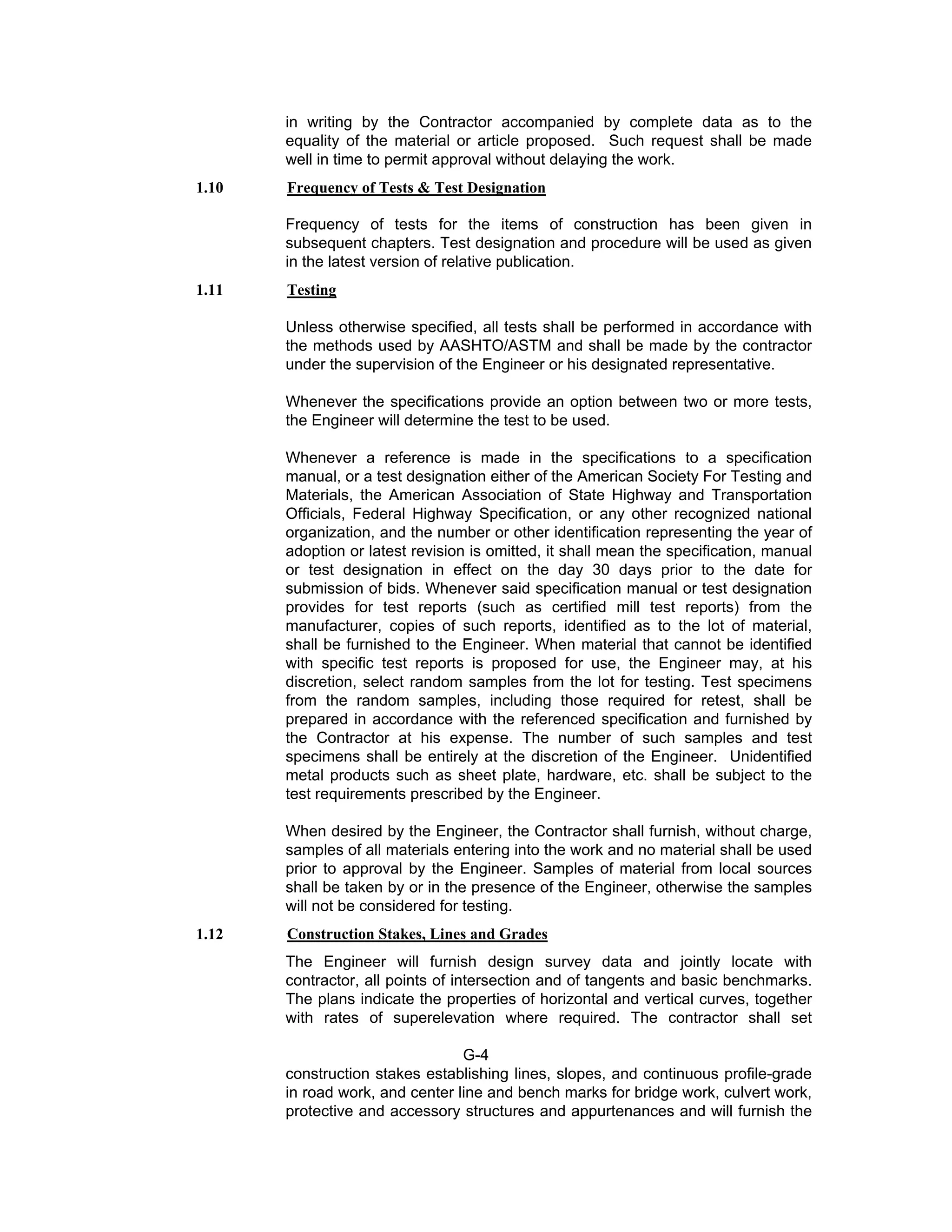


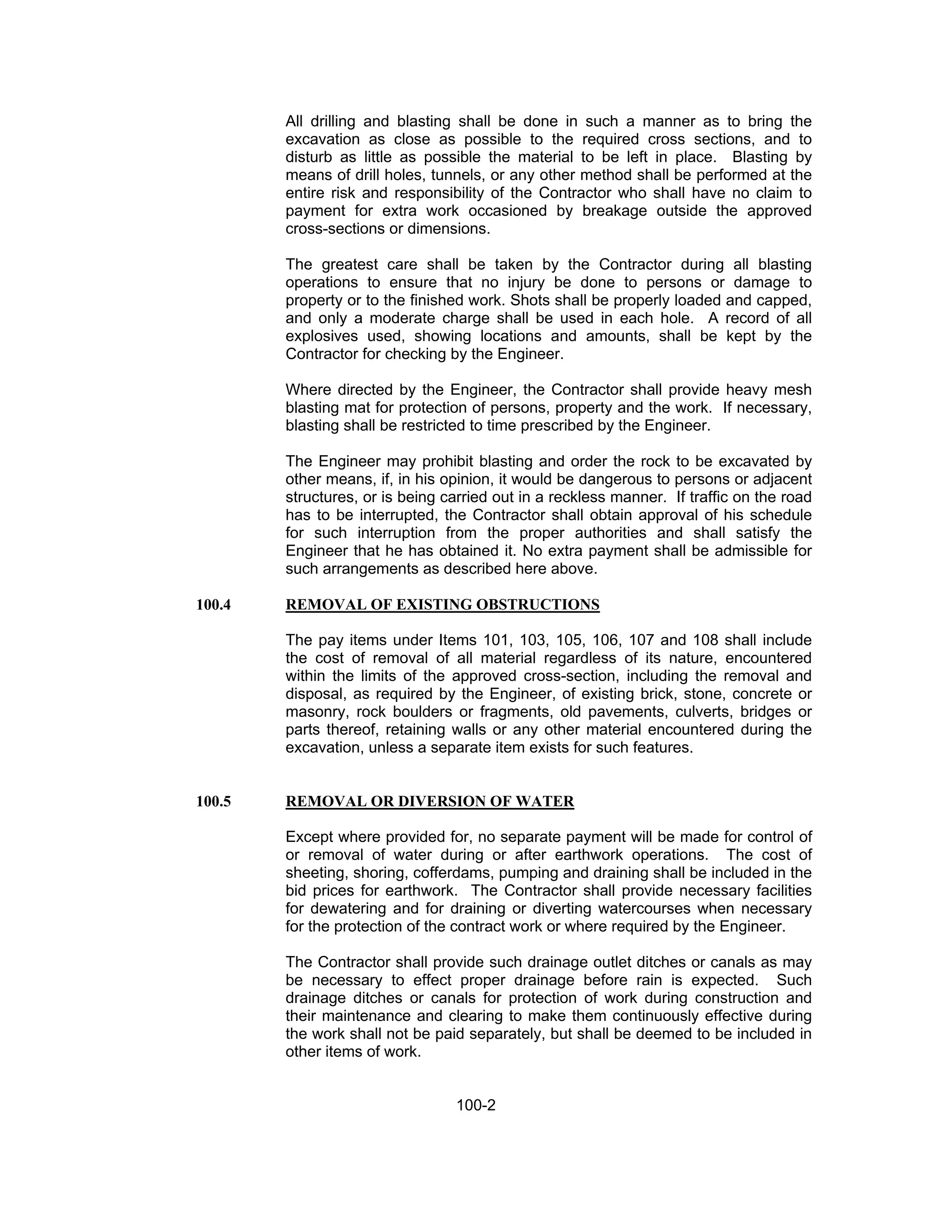


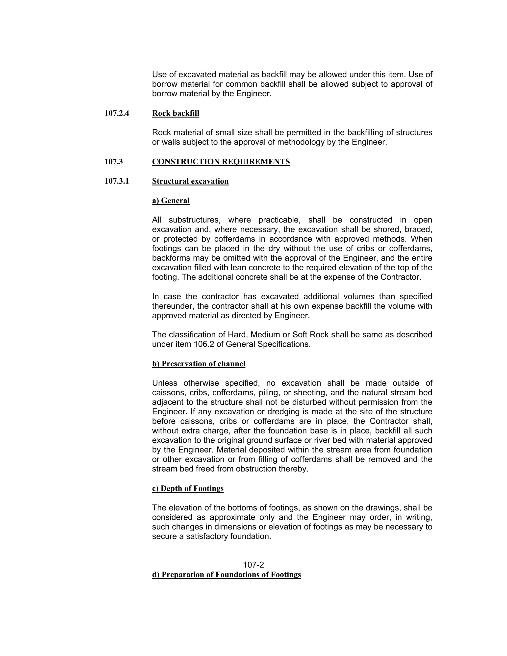


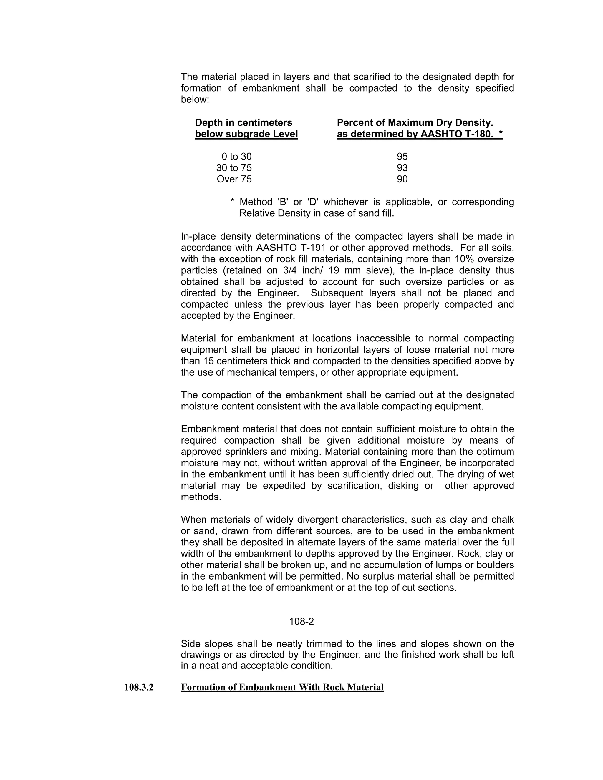


![capacity for piles driven in the sub-soils at the site. Piles shall be driven to a
final resistance as indicated on the plans determined by the following
formula:
407-5
For drop hammer
Qall = WH/[6(S+2.5)]
For single-acting steam or air hammers and for diesel
Hammers having unrestricted rebound of rams.
Qall = WH/[6(S+0.25)] (Use when driven
weights are smaller
than striking weights)
Qall = WH/[6{S+0.25(WD/WS)}] (Use when driven
weights are larger than
striking weights)
For double-acting steam or air hammers
and diesel hammers having enclosed rams
Qall = E/[6(S+0.25)] (Use when driven
weights are smaller
than striking weights).
Qall = E/[6{S+0.25(WD/WS)}] (Use when driven
weights are larger than
striking weights)
In the above formulas:
Qall = Allowable pile load in Kilograms.
W = Weight of striking parts of hammer in Kilograms.
H = The height of fall in centimeters for steam, and air
hammers, and the observed average height of fall in
centimeters, of blows used to determine penetration for
diesel hammers with unrestricted rebound of hammer.
S = Average net penetration per blow in centimeters for the
last 10 to 20 blows of steam, air, or diesel hammer; or
for the last 15 centimeters of driving for a drop hammer.
E = The actual energy delivered by hammer per blow in
Kilogram - centimeter.
WD = Driven weights in Kilograms
Note: Ratio of driven weights to striking weights should not exceed
three.
WS = Weight of striking parts in Kilograms.](https://image.slidesharecdn.com/generalspecificationsnha-240308043927-473b474f/75/most-important-General-Specifications-NHA-pdf-304-2048.jpg)


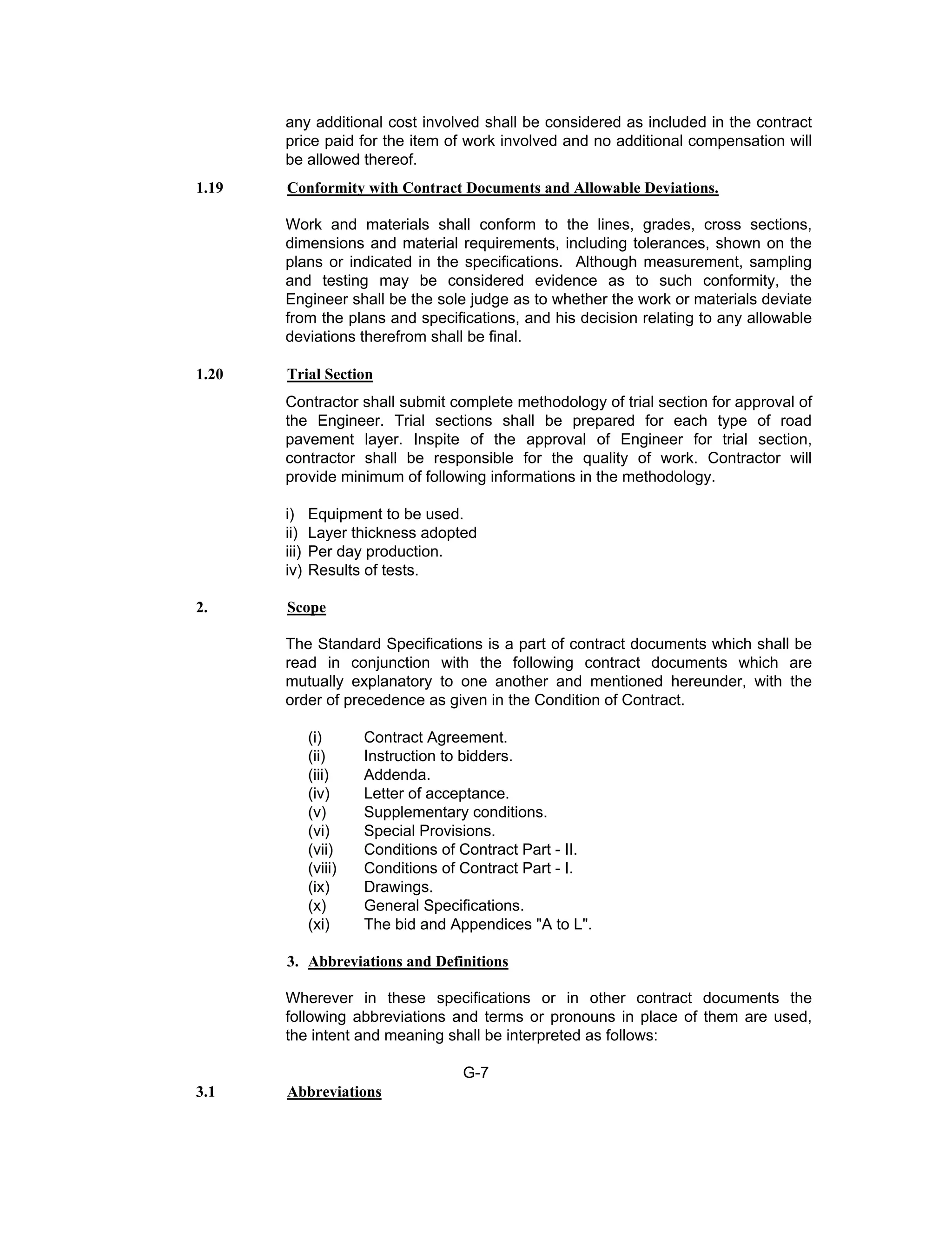
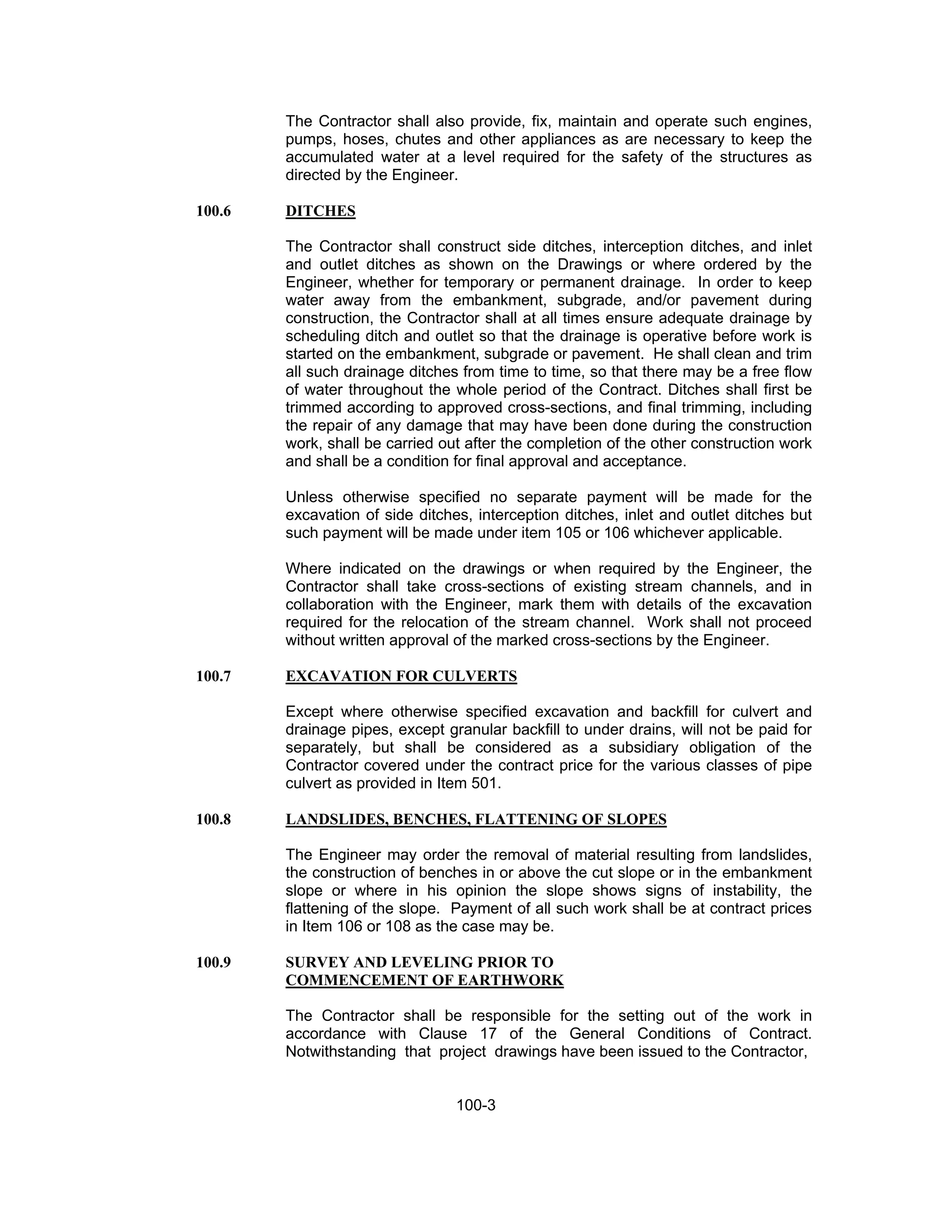
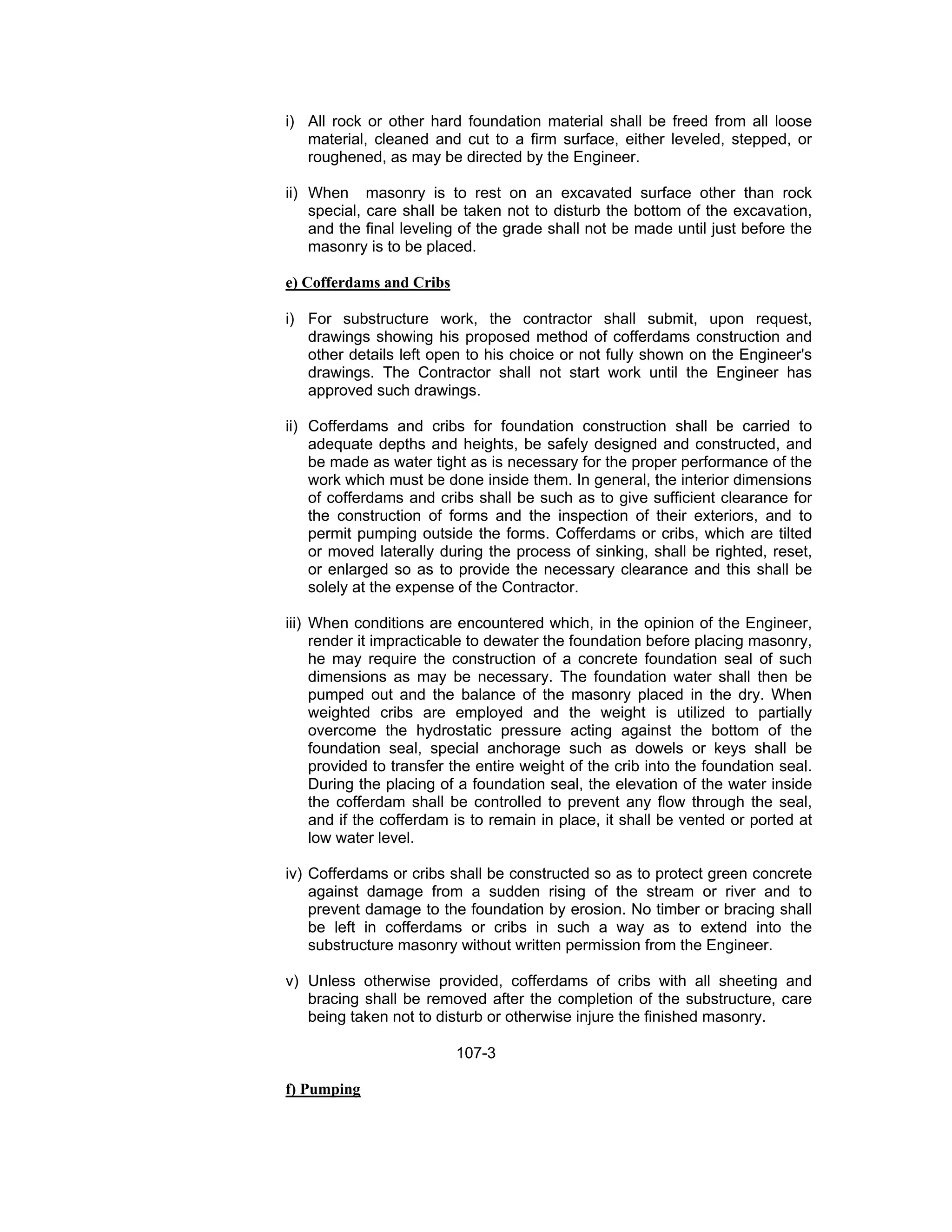
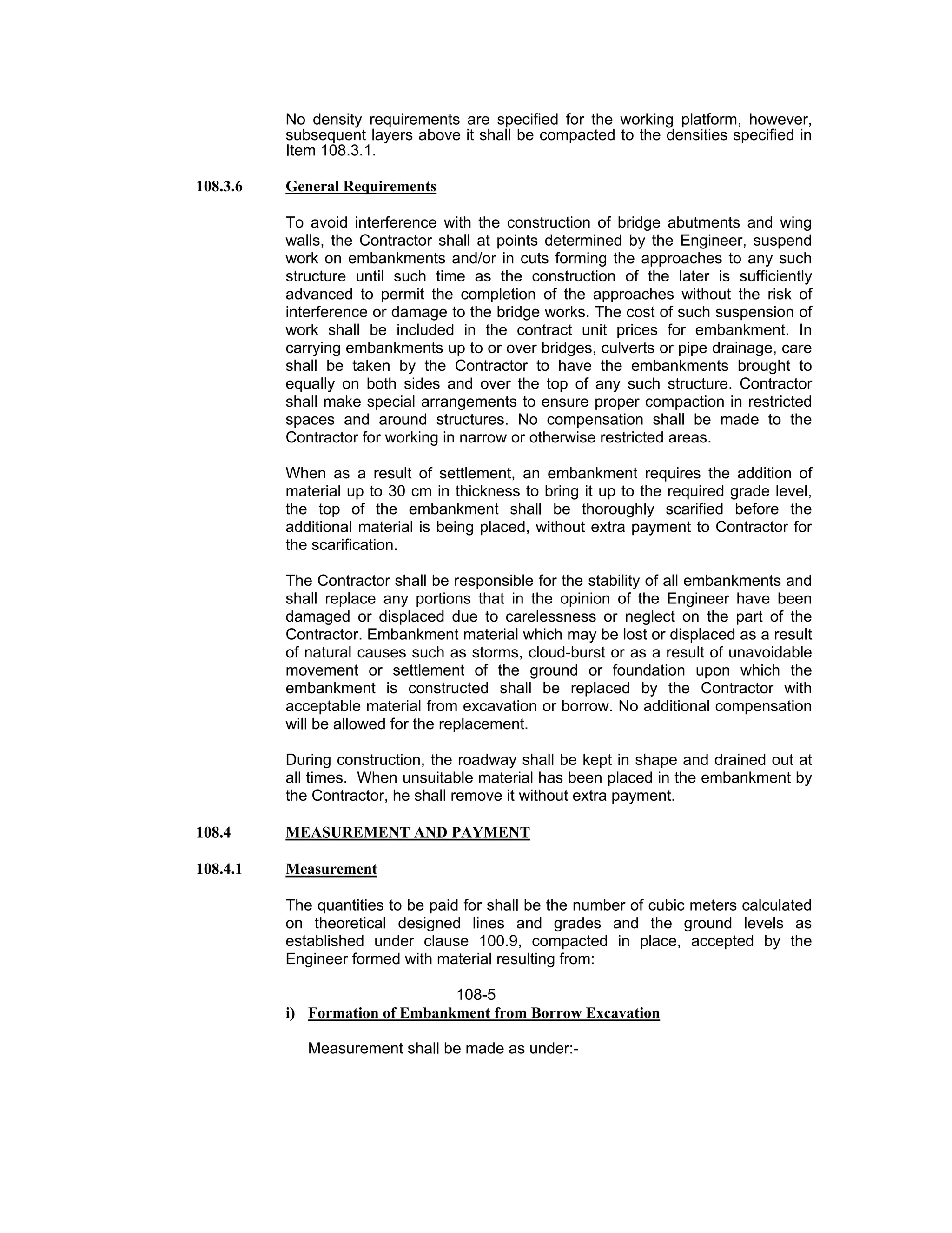
![The marking film shall be durable retroreflective plisot polymer pavement
marking film for performed longitudinal markings subject to low to medium
traffic volumes and moderate wear conditions such as repeated shear
action from crossover or encroachment on channelization lines.
608-9
The retroreflective pavement marking film shall consist of mixture of high-
quality pigmented polymeric materials, with a reflective layer of ceramic and
glass beads, and a layer of skid resistant ceramic particles bonded to the
top urethane wear surface. The film shall have a pre-coated pressure
sensitive adhesive. The edges of the preformed tape shall be clear cut and
true.
608.4.2 Colour:
The daytime colour of the white film shall provide a minimum initial
Luminance factor, Y, of 80, and shall conform to the following chromaticity
requirements: X = 0.290, Y = 0.315; X = 0.491, Y = 0.435; X = 0.512, Y =
0.486; X = 0536, Y = 0.463.
Measurements shall be made in accordance with ASTM E 1349, using
illuminent “C” and 0/45 (45/0) geometry. Calculations shall be in accordance
with ASTM E 308 for the 2
o
standard observer.
608.4.3 Reflectance.
The white and yellow films shall have the following initial minimum
reflectance values as measured in accordance with the testing procedures
of ASTM D 4061. The photometric quantity to be measured shall be specific
luminance (SL), and shall be expressed as millicandals per square foot per
foot-candle (mcd. ft-2
). fc -1
). The metric equivalent shall be expressed as
millicandals per square meter per lux (mcd. m -2
). lx-1
)
White Yellow
Entrance Angle 86.5o
86.5o
Observation Angle 1.0o
1.0o
Specific Luminance 300 175
SL [(mcd. ft-2
). Fc-1
]
608.4.4 Skid Resistance
The surface of the retroreflective films shall provide an initial minimum skid
resistance values of 55 BPN as measured by the British Portable Skid
Tester in accordance with ASTM E 303.
608.4.5 Patchability
The pavement marking film shall be capable of use for patching worn areas
of the same type of film in accordance with the manufacturer’s instructions.
608.4.6 Reflectance Retention.](https://image.slidesharecdn.com/generalspecificationsnha-240308043927-473b474f/75/most-important-General-Specifications-NHA-pdf-440-2048.jpg)


![Geotechnical Engineering-I [Lec #12: AASHTO Soil Classification]](https://cdn.slidesharecdn.com/ss_thumbnails/12-180923183952-thumbnail.jpg?width=640&height=640&fit=bounds)


![Geotechnical Engineering-I [Lec #5: Phase Relationships - Problems-2]](https://cdn.slidesharecdn.com/ss_thumbnails/5-180923180153-thumbnail.jpg?width=640&height=640&fit=bounds)


![Geotechnical Engineering-I [Lec #2: Introduction-2]](https://cdn.slidesharecdn.com/ss_thumbnails/2-180923175525-thumbnail.jpg?width=640&height=640&fit=bounds)


![Geotechnical Engineering-II [Lec #26: Slope Stability]](https://cdn.slidesharecdn.com/ss_thumbnails/26-181125070353-thumbnail.jpg?width=640&height=640&fit=bounds)
![Geotechnical Engineering-II [Lec #17: Bearing Capacity of Soil]](https://cdn.slidesharecdn.com/ss_thumbnails/17-181123045836-thumbnail.jpg?width=640&height=640&fit=bounds)

![Geotechnical Engineering-II [Lec #4: Unconfined Compression Test]](https://cdn.slidesharecdn.com/ss_thumbnails/4-180930132645-thumbnail.jpg?width=640&height=640&fit=bounds)

![Geotechnical Engineering-II [Lec #6: Stress Distribution in Soil]](https://cdn.slidesharecdn.com/ss_thumbnails/6-180930132732-thumbnail.jpg?width=640&height=640&fit=bounds)
![Geotechnical Engineering-II [Lec #28: Finite Slope Stability Analysis]](https://cdn.slidesharecdn.com/ss_thumbnails/28-181125070402-thumbnail.jpg?width=640&height=640&fit=bounds)


