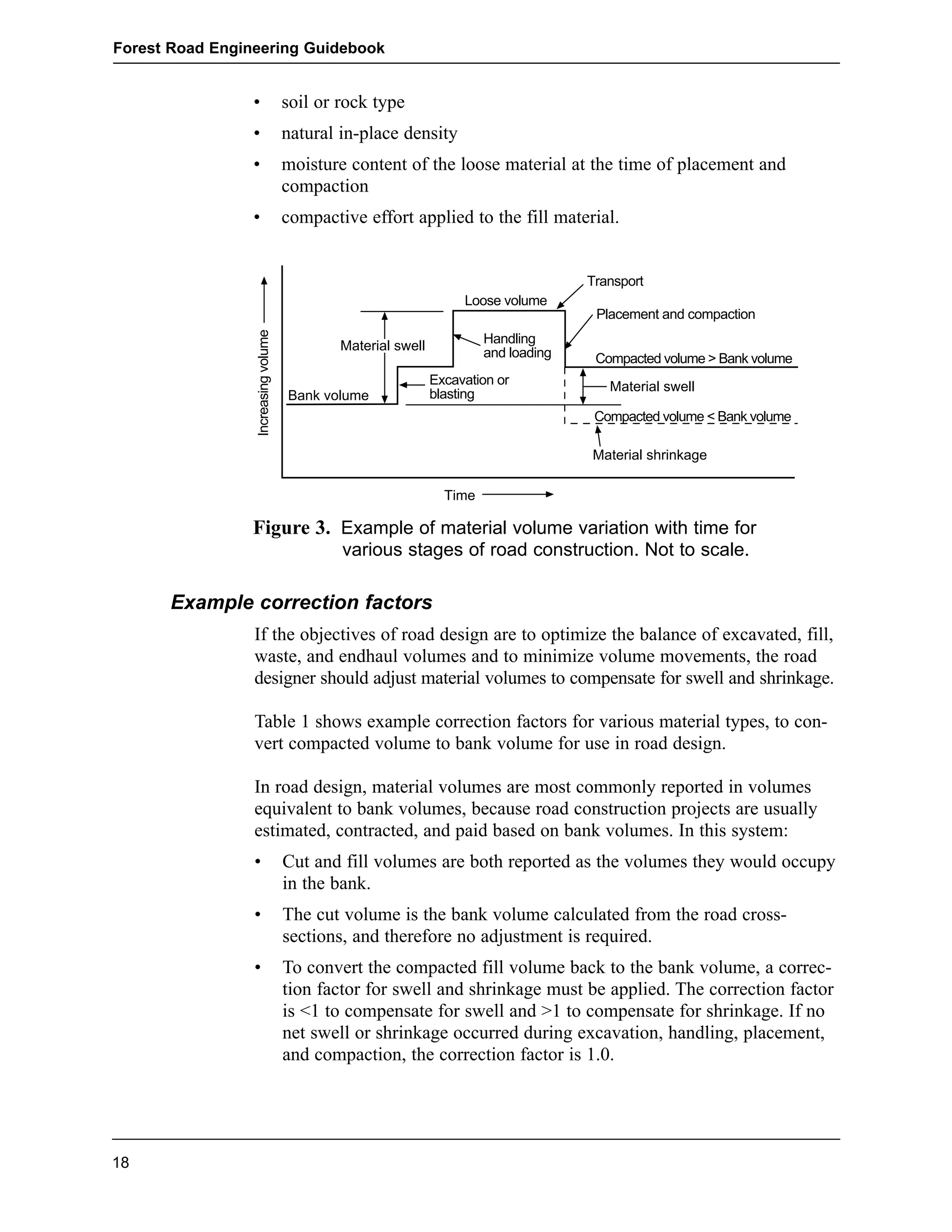
1. of
BRITISH COLUMBIA
Forest Road Engineering
Guidebook
Second edition
June 2002
Ministry of Forests
2.
3. of
BRITISH COLUMBIA
Forest Road Engineering
Guidebook
Second edition
June 2002
Authority
Forest Practices Code of British Columbia Act
Forest Road Regulation
Operational Planning Regulation
5. Foreword
Forest Road Engineering Guidebook
This guidebook provides forest road practitioners with advice on road design
and field practices to assist them to achieve the statutory and regulatory
requirements in the Forest Practices Code of British Columbia Act, the
Forest Road Regulation, and the Operational Planning Regulation.
The practices contained in this document are not mandatory and are not to be
interpreted as the only acceptable options. However, as the Chief Engineer
for the Ministry of Forests, I believe that by using the suggested procedures,
a proponent will more likely be successful in addressing his or her legal
responsibilities, at least where the actual site situation matches the conditions
contemplated by the documented practices. The practices described in the
document have been prepared and reviewed by experts in their field, includ-ing
both public and private sector technicians and professionals. Accordingly,
I believe this guidebook is a reasonable reflection of acceptable standards of
practice in the forest sector of British Columbia.
Where a range of options or outcomes apply, such ranges have been given.
Where these are not provided, some flexibility may be required in applying
the guidebook practices, particularly where the proponent believes that such
variance is warranted based on site-specific conditions.
Ron Davis, P.Eng.
Ministry of Forests
Chief Engineer - Senior Policy and Standards Engineer
iii
11. Introduction
Forest Road Engineering Guidebook
The materials presented in this guidebook are intended primarily for skilled,
experienced, and knowledgeable technical personnel who are responsible for
locating, designing, building, maintaining, and deactivating forest roads. It is
aimed at those personnel who are already carrying out technical operations
related to forest road engineering, but who may require guidance on how
to interpret and meet the requirements of the Forest Practices Code of
British Columbia Act (Act), and associated regulations. This guidebook is a
result of many contributions from ministry staff and forest company practi-tioners,
as well as a number of consultants.
Throughout this guidebook, emphasis is placed on compliance with opera-tional
and safety requirements and the need to ensure protection of forest
resources, while meeting the requirements of the Forest Practices Code statu-tory
obligations in an effective, efficient manner. The guidebook materials
are grouped into six subject areas that correspond to the following work
phases:
1. Road Layout and Design—This section describes route selection and
layout, field investigation, surveying, and associated engineering prac-tices
to provide site-specific road location, design, and construction
specifications.
2. Design and Construction of Bridges and Stream Culverts—This sec-tion
outlines the general design requirements for bridges and stream cul-verts,
and discusses non-professional and professional design responsibil-ity,
site and site survey information requirements for bridges and major
culverts, preparation of construction drawings, specifications for bridges,
major culverts, and stream culverts, and methods to estimate design flow
discharge for streams.
3. Road Construction—This section presents information to assist technical
personnel responsible for forest road construction and modification in
constructing roads appropriate for the expected service life while mini-mizing
any adverse impacts on other forest resources.
4. Road Drainage Construction—This section covers drainage system
construction, the purpose of which is to maintain natural surface drainage
patterns while intercepting, collecting, and controlling flows to minimize
any adverse impacts to the environment.
5. Road and Structure Inspection and Maintenance—This section pro-vides
information to assist those responsible for the inspection and main-tenance
of roads and associated structures.
6. Road Deactivation—This section describes the objectives, levels, and
techniques of forest road deactivation to provide practitioners with
administrative and process-oriented guidance.
1
13. 1. Road Layout and Design
Introduction
Forest Road Engineering Guidebook
Forest road layout and design is a process that includes route selection, field
investigation, surveying, and analysis to provide a site-specific road location
and design. Road design provides construction specifications, road prism
geometry, stream crossing site information, and information necessary for
construction control.
The detail and information required for each phase in this process varies with
the type of road required, the complexity of terrain, the size and complexity
of stream crossings, and other resource values.
This chapter:
• describes the types of projects for which the district manager’s approval
of road layout and design for construction and modification is mandatory
• provides information on route selection and layout, and describes the
content requirements of a reconnaissance report
• provides criteria for survey level selection, and explains the types of sur-vey
(field traverse and location survey), and the suitability and applica-tion
of different survey levels
• provides procedures for field traverses and location surveys
• explains general and geometric road design requirements
• provides example correction factors to convert compacted volume to
bank volume for road design purposes
• discusses slope stability considerations if a proposed road will cross areas
with a moderate or high likelihood of landslides
• provides road design specifications and parameters.
District manager approval of road layout and design
The Ministry of Forests has developed a package of road layout and design
forms and administrative procedures that incorporate the statutory contents
for road layout and design. This information can be found at an appropriate
Ministry of Forests website.
The district manager approves road construction and modification for forest
roads under various permits. In general, unless the district manager requires
it, the following types of projects are exempted from needing his or her
approval of road layout and design:
3
14. Forest Road Engineering Guidebook
• in-block roads, unless they cross areas with a moderate or high likelihood
of landslides as determined by a terrain stability field assessment (TSFA),
or unless they are in community watersheds and surface soil erosion
potential or hazard is high or very high;
• stream-crossing modifications, unless the work consists of replacement or
new construction of bridges or major culverts; and
• emergency works.
Route selection and layout
Decisions made at the route selection stage may have long-term effects on
road construction and maintenance costs, user safety, and other resources.
Routes must be selected and located to meet the objectives of higher-level
plans within the constraints of any approved operational plans or permits. It
is essential that adequate time and resources be allocated to route selection.
The route selection stage begins with the collecting and analyzing of all
available information for the development area, focusing on the route corridor.
This information may include aerial photos, topographic maps, soil erosion
potential maps, land alienation maps, and reconnaissance terrain stability or
detailed terrain stability maps and other assessments for the area.
The method of harvesting and constraints of the harvesting system should
also be considered if the road will traverse (1) a harvesting area or (2) an
area that could be harvested in the future. Road drainage flows and drainage
structures and road and clearing widths could all be affected by harvesting.
Control points (physical features that may influence road location or design)
should then be plotted on the aerial photos and/or topographic maps of a suit-able
scale.
Control points include:
• stream crossings, rock bluffs, benches, passes, saddles, and other domi-nant
terrain features
• road grades and switchback locations
• harvesting system landings
• potential endhaul or waste areas
• alienated lands, including powerline, gas pipeline, or railway crossings
• current access and junction to existing roads.
Route selection should then be made based on an analysis of all of the avail-able
information, and the route should be field verified.
4
15. The route selection field phase is an on-the-ground check of the proposed
route or potential routes, taking into consideration control points or other
constraints. This field traverse is also known as a Level 1 survey (measure-ments
are not usually accurate enough for detailed road design) and is run
along a proposed route to confirm that the horizontal and vertical alignment
are suitable. Adjustments to the line may be necessary, and often several iter-ations
are needed to establish the alignment and confirm the choice of route.
The person carrying out the field traverse should make sufficient notes to
prepare a detailed reconnaissance report to assist the location surveyors, road
designers, and road builders.
The reconnaissance report should identify and or confirm:
• terrain conditions and road sections that are in unstable or potentially
unstable terrain
• road sections with side slopes over 60% or where slope instability is
found
• control points and topographic features (e.g., rock bluffs, swamps, ava-lanche
paths, landslides, and debris slides), including those that may be
used as photo ties
• the sections of road that encroach on public utilities
• the sections of road that are adjacent to or cross private property, Crown
leases, or mineral and placer claims or leases (where possible, alienated
lands should be avoided)
• all continuous and intermittent drainage flow channels, springs, seeps,
and wet areas
• riparian areas
• stream crossings where channel and bank disturbances can be prevented
or mitigated, locations that require site plans, and data required for minor
stream crossings
• forest cover (species composition, timber quality, and volume per
hectare)
• recommended slash and debris disposal methods and additional clearing
widths required for the slash and debris disposal
• soil types based on visual observations of exposed cuts, shallow hand-dug
test holes and probing, and the location of these soils on maps or aer-ial
photos (see Appendix 1 for a method of identifying soils)
• maximum road grades and minimum curve radii
• location and extent of bedrock, if rippable, and the potential as ballast
• location and extent of gravel sources and the potential for use as sub-grade
and surfacing materials
Forest Road Engineering Guidebook
5
16. Forest Road Engineering Guidebook
• endhaul sections and potential waste areas
• recommended construction methods and potentially appropriate alterna-tives
• recommended survey level or levels appropriate for the terrain.
The field reconnaissance report should also record the characteristics of
existing roads in the vicinity of the proposed road location by identifying and
recording soil types, stable cut and fill slope angles, and existing sources of
road surfacing materials.
Field reconnaissance is an appropriate stage to evaluate the need for any
additional information or assessments that may include:
• TSFAs
• riparian classification of streams, wetlands, and lakes
• identification of fish streams in community watersheds
• visual impact assessments
• archaeological impact assessments
• soil erosion field assessments.
Survey level selection
There are two general types of surveys: a field traverse and a location survey.
There are also four levels of survey intensity: Survey Levels 1, 2, 3, and 4.
These survey types and levels are briefly explained below.
To determine which survey type and level to recommend in the reconnais-sance
report, the physical characteristics of the terrain, design complexity,
and desired road prism geometry should be considered.
Types of survey
Field traverse
A field traverse is required for road layout and design and is conducted to
collect data and measurements for the road location. A field traverse is also
sometimes referred to as Survey Level 1 (see “Survey levels” below).
Location survey
A location survey is carried out to obtain information and measurements
necessary for detailed design, or to obtain information when geometric road
designs are required. Compared to a field traverse, a location survey is carried
out at a higher level of survey intensity (i.e., Survey Level 2, 3, or 4).
6
17. Forest Road Engineering Guidebook
If as-built surveys are required for volume determination or to check confor-mance
to the design, the location survey level should be suitable for accu-rately
re-establishing the road centreline location.
If construction surveys are required, the location survey level should be suit-able
to accurately re-establish the construction control points.
The accuracy achieved with any survey level depends, in part, on the type
and condition of survey equipment used, the competence of the crew, and the
field methods used. Global Positioning System (GPS) receivers, like other
survey equipment, are acceptable when they can achieve the required hori-zontal
and vertical accuracy for the appropriate survey level.
Stream crossings require special consideration. Site information requirements
for bridge and culvert planning and design are provided later in this chapter.
Winter-constructed roads require special layout considerations to identify the
location of cross-drains and stream crossings. Long continuous grades should
be avoided, since they easily become conduits for meltwater and groundwater
seepage. Steep cut banks should be avoided because they may slough or fail,
blocking ditches and sending ditchwater onto the road surface and creating
the potential for major surface erosion.
Survey levels
The following criteria are used to determine the appropriate survey level for
a field traverse (Survey Level 1) or location survey (Survey Levels 2, 3,
or 4).
Survey Level 1 (for field traverses)
Application: For field traverses on stable terrain with a low likelihood of
landslides and where geometric road design, construction surveys, and
as-built surveys are not required. The necessary accuracy of survey may be
achieved with basic field equipment such as hand compass, clinometer, and
hip chain.
Horizontal accuracy: Turning points are established to a relative accuracy
of 1:100.
Vertical accuracy: Not applicable.
Survey Level 2 (for location surveys on stable terrain)
Application: For location surveys on stable terrain with a low likelihood of
landslides and where a geometric road design, construction surveys, or
as-built surveys are desired.
7
18. Forest Road Engineering Guidebook
Horizontal accuracy: Turning points to be established to a relative accuracy
of 1:300.
√ total horizontal distance measured in kilometres
Vertical accuracy: = , expressed
in metres. For example, the vertical accuracy for a 1-km road is 1 m. For a
2-km road, the vertical accuracy is 1.41 m.
Survey Level 3 (for location surveys within areas of
moderate or high likelihood of landslides)
Application: For location surveys, construction surveys, geometric road
design, and as-built surveys in areas of moderate to high likelihood of land-slides
as determined by a TSFA. Appropriate level of survey for material
volume determination and detailed-engineered estimates. This level of survey
may also be used for bridge and major culvert planning and design, but
greater vertical accuracy would possibly be necessary.
Horizontal accuracy: Turning points to be established to a relative accuracy
of 1:1000.
√ total horizontal distance measured in kilometres
Vertical accuracy: = 0.5 × ,
expressed in metres. For example, the vertical accuracy for a 1-km road is
0.5 m. For a 2-km road, the vertical accuracy is 0.71 m.
Survey Level 4 (for high-order survey requirements)
Application: A high-order survey for location surveys, construction surveys,
construction contracting on a cost-per-unit basis, check surveys, placement of
permanent bridges, as-built surveys through Crown leases, mineral and placer
claims, and leases, private property, and surveys to re-establish private prop-erty
lines.
Horizontal accuracy: Turning hubs are to be established to a relative accura-cy
of 1:5000.
√ total horizontal distance measured in kilometres
Vertical accuracy: = 0.3 × ,
expressed in metres. For example, the vertical accuracy for a 1-km road is
0.3 m. For a 2-km road, the vertical accuracy is 0.42 m.
Procedures for field traverses and location surveys
This section outlines the minimum requirements for field traverses and loca-tion
surveys. Although considerable gains have been made in survey instru-mentation
technology, use of the technology does not preclude the need to
follow standard survey practices. Standard practices are outlined in the
Manual for Roads and Transportation (BCIT 1984).
8
19. Survey Level 1 (for field traverses)
Forest Road Engineering Guidebook
Where no location survey is required (e.g., where a proposed road will not
cross areas with a moderate or high likelihood of landslides as determined by
a TSFA):
1. Clearly identify the beginning and end of the road.
2. Clearly flag the proposed centreline of the road.
3. Using an appropriate method (such as aluminum plaques and tree blazes),
mark and record control points, noting the control point number, station,
bearing, and horizontal distance from the proposed centreline.
4. Record notes on forest cover, vegetative types, soil types, rock, ground
water seepage, streams, etc.
Survey Levels 2 and 3 (for location surveys)
Traverse
1. Clearly identify the beginning and end of the road.
2. Establish intervisible stations called turning points (TPs) if using a com-pass
or traverse hubs if using a transit—along the preliminary centreline
(P-Line). Use manufactured stakes or local material (blazing of saplings)
driven into the ground.
3. Measure the bearing, slope gradient, and distance between TPs and mark
the cumulative chainages and/or point number in the field.
4. Measure the slope gradient and distance to additional grade breaks
between TPs as intermediate fore shots to facilitate taking cross-sections
at those locations.
5. Using an appropriate method (such as aluminum plaques and tree blazes),
mark and record control points, reference points and bench marks, noting
the number, station, bearing, and horizontal distance from the P-Line.
6. Record notes on forest cover, vegetative types, soil types, rock, ground
water seepage, streams, etc. that were not identified on the reconnais-sance
report.
7. Obtain enough information to ensure that road junctions can be designed
and constructed. Switchbacks located on steep slopes also require
detailed data for proper design and construction.
8. The final designed road location centreline (L-Line) should be close to
the P-Line and generally within 3 m of the P-Line if the road will cross
areas with a moderate to high likelihood of landslides as determined by a
TSFA, or if bedrock is present or switchbacks are encountered.
9
20. Forest Road Engineering Guidebook
Cross-sections
1. Take cross-sections at all TPs and intermediate fore shots perpendicular
to the back tangent or bisecting the interior angle of two tangents. Ensure
that the recorded information is compatible with computer design soft-ware
requirements.
2. Cross-sections should not be more than 15 m apart in rock or 30 m apart
in other material. A longer spacing will not provide sufficient cross-sections
for the accurate earth volume calculations required for geometric
design. Exceptions to this guideline may be considered for Level 2 sur-veys
conducted in uniform terrain.
3. Extend cross-sections at least 15 m horizontally on either side of the
location line or farther to accommodate the road prism and in areas con-sidered
for waste disposal.
4. Measure and record slope breaks (over 10%) on the cross-section profile
to the nearest 0.1 m in distance and nearest 1% in slope gradient.
5. Take additional cross-sections to record features that may affect the road
prism on each side of the proposed centreline. Examples of such features
are rock outcrops, flat topography (benches), lakeshores, fences, streams,
back channels, and existing roads.
Referencing and benchmarks
A reference tree or other fixed object (e.g., bedrock outcrop) is used for the
horizontal control, and a benchmark is used for the vertical control of the
road traverse. Both are important for re-establishing the designed location
line (L-Line), and are required for construction surveys and those surveys
necessary to complete as-built documentation.
1. Reference the beginning and end of the location line traverse. When
switching from one survey level to another, reference this point in accor-dance
with the higher survey level accuracy.
2. Establish references at least every 300 m, and at control points estab-lished
during the field traverse.
3. Use two trees to establish references outside the proposed upslope clear-ing
limit. Set the angle from the TP to the two reference trees between
60° and 120° from the centreline tangent. Make horizontal measurements
to the centre of the reference marker (plaque). (The use of two reference
trees improves the accuracy of relocating the traverse station and provides
for a back-up if one tree is destroyed.) Use the same level of survey accu-racy
to establish references and benchmarks.
4. Record the diameter at breast height (dbh) and species of the reference
trees so that they can easily be found.
10
21. Forest Road Engineering Guidebook
5. Establish benchmarks outside the clearing width no more than 1 km
apart, at major structures and at existing references for control points
established during the field traverse.
6. A typical benchmark and road survey reference information is shown in
Figure 1.
Ties to existing property boundaries
Traverse-tie the location survey to existing property markers or other evi-dence
of legal boundaries that may be near the location survey. Sufficient
investigation should be completed to establish the location of the property
line and determine whether the road right-of-way will encroach on the prop-erty
line. If possible, the centreline and right-of-way should be relocated if
there is an encroachment.
Survey Level 4 (for high-order survey requirements)
As noted earlier, this high-order survey is also suitable for alienated lands
such as private property. Before starting work on alienated lands, contact the
owners and explain the nature of the work. The owner may be able to pro-vide
the location of corner pins and other useful information.
When working on alienated lands, keep the clearing (tree falling, line slash-ing,
etc.) and marking of lines to a minimum. The following information
should be recorded and tied to the location line traverse:
• all existing legal markers
• improvements and utilities that may be affected by the right-of-way
• fences and buildings
• parts of the existing road if applicable, including the top of cut, toe of fill,
grade, and ditchline.
If possible, close traverses onto at least two legal posts to ensure accuracy
and establish correct orientation of the survey with respect to the legal lot or
lots.
11
22. Forest Road Engineering Guidebook
Road design requirements
The purpose of road design is to produce design specifications for road con-struction
by determining the optimum road geometry that will accommodate
the design vehicle configuration for load and alignment, and traffic volume,
and provide for user safety, while minimizing the cost of construction, trans-portation,
maintenance, and deactivation. The optimum road design should
minimize impacts on other resources by minimizing clearing and road
widths, minimizing excavation, using rolling grades, and installing proper
drainage structures.
Road design software has been developed to replace manual drafting and
repetitious design calculations so that various alignment alternatives can be
quickly evaluated. Once the location survey data have been entered into the
road design program, select and input appropriate design parameters for the
specific project. Ensuring this requires direction from a skilled and knowl-edgeable
designer familiar with forest road layout, design, and construction
practices. As each phase of road layout and design builds on the previous
phase, the quality of the final design depends on the appropriateness of the
road location, field data, and survey—and the competence of the designer.
General design requirements
This section provides road design requirements common to all levels of road
layout and design. Construction techniques, road width, cut and fill slope
angles, and horizontal and vertical control angles are selected according to
terrain and soil conditions for the required road standard. Forest road stan-dards
are defined primarily in terms of stabilized road width and design
speed.
12
Survey flagging
Plaque
(include road survey
reference information,
see details to left)
1.2 m
ROAD SURVEY REFERENCE
B.M.# 10
ELEV. 671.11
REFERENCE# 20
STA. 15 + 300.41
BRG. 110° 50'
DIST. 18.23
PROJECT NAME_______________
SURVEYOR NAME____________
DATE (Day/Mo/Yr) _______________
Benchmark
Figure 1. Typical benchmarks and reference.
23. Road design specifications consist of alignment elements (e.g., horizontal
curvature, vertical curvature, road grade, and sight distance) and cross-section
elements (e.g., full or partial bench construction, sidecast construction, road
width, angles of repose for stable cut slopes, ditch dimensions, drainage
specification, and clearing widths).
Geometric road designs include plans, profiles, cross-sections, and mass haul
diagrams showing the optimum balance of waste, borrow, and endhaul vol-umes.
The designs are generated from the route selection process and the
location survey. From the location survey information, a road centreline
(L-Line) is designed for vertical and horizontal alignment, earthwork quanti-ties
are calculated, and a mass haul diagram is produced to show the optimum
placement of excavated material.
Figure 2 shows a typical road cross-section and the terminology used to
describe cross-section elements.
Factors to consider in road design
Road design should consider the following factors:
General considerations:
• intended season and use of the road (design vehicle configuration for
load and alignment, and traffic volume)
• climate (heavy snowfall areas, heavy rainfall areas, etc.)
• design service life of the road
• user safety
• resource impacts
• economics
• road alignment (horizontal and vertical geometry)
• junctions with existing roads
• road width (turnouts and widenings).
Soils, road prism geometry, slash disposal:
• the measures to maintain slope stability if the road will cross areas with
a moderate or high likelihood of landslides (also see “Geometric road
design requirements” below)
• soil types (including the use of appropriate conversion factors to adjust
for swell and shrinkage of materials)
• cut and fill slope angles
• clearing widths
• slash disposal methods
Forest Road Engineering Guidebook
13
24. Forest Road Engineering Guidebook
• planned movement and placement of materials (balancing of design),
including waste areas and endhaul areas.
Drainage, construction techniques, sediment prevention, road
deactivation:
• culverts (locations, type, size, and skew angles)
• drainage and ditch (including depth) locations
• rock blasting techniques to optimize usable rock
• anticipated construction problems
• measures to mitigate soil erosion (including vegetative requirements and
prescriptions)
• measures to maintain water quality
• future deactivation requirements.
14
25. Forest Road Engineering Guidebook
15
Clearing width (see Appendix 5)
Top of cut Toe of fill
Road prism
Road
subgrade
width
Slash and debris
pulled back onto
fill slope
3m*
* Default distance from
tables in Appendix 5
(distance may be less)
Stable
angle
Figure 2. Typical roadway on moderate slopes with no additional clearing.
26. Forest Road Engineering Guidebook
Geometric road design requirements
A geometric road design is mandatory for all roads that will cross areas with
a moderate or high likelihood of landslides as determined by a TSFA. In
these areas, it is also mandatory that measures to maintain slope stability be
incorporated into the geometric road design. These measures rarely allow for
the most optimum balance of waste, borrow, and endhaul volumes.
In geometric road design, specifications such as road width, cut and fill slope
angles, and horizontal and vertical control angles are selected to match the
required road standard. A road centreline location (L-Line) is designed based
on information from the location survey and reconnaissance report.
Earthwork volumes or quantities are then calculated.
In addition to the information described under “General design requirements”
above, a geometric road design should also provide:
• plans and profiles (see Appendix 3 for recommended content and layout)
• cross-sections with road prism templates
• mass diagrams with balance lines
• correction factors used in the design to convert compacted volume to
bank volume
• a schedule of quantities and units of measure for clearing, grubbing,
excavating (other material and rock), and gravelling
• planned movement and placement of materials (balancing of design)
• the location and size of required drainage structures such as culverts and
bridges
• the location and size of retaining walls or specialized roadway structures
• clearing widths
• typical construction equipment required, and any equipment recommend-ed
for specialized construction techniques
• estimated material and construction costs
• location survey alignment and designed centreline (L-Line) offsets, and
clearing width offsets shown on the site plan
• slope stake information (note that this information is only a guide and
slope/grade stakes should be calculated and placed based on design or
re-design of cuts and fills at centreline)
• measures required for reducing potential impacts on other resource values
• site-specific design and construction notes and prescriptions on, for
example, the location of endhaul sections, borrow pits, waste and slash
disposal areas, and full bench cut areas, and any other information that
the designer considers useful to the road builder
16
27. Forest Road Engineering Guidebook
• measures to maintain slope stability if the road will cross areas with a
moderate or high likelihood of landslides as determined by a TSFA
• information that the designer considers useful to the road builder or
owner.
Whenever possible, the design should allow for the use of waste or spoil
material in ways that reduce endhauling requirements. For example, some
material types may be used for the road subgrade, base course, turnouts,
curve widenings, and embankment (fill). If these options are not available, or
if the excess material consists of overburden and debris, then spoil sites
should be identified as close to the construction area as possible. Abandoned
quarries, gravel pits, and roads are some possibilities. Alternatively, stable
areas in gentle or benched terrain can be evaluated for use as spoil sites.
Correction factors to adjust for swell and shrinkage of materials
Material volumes (bank, loose, and compacted)
The volume of natural in-place material usually expands (swells) or contracts
(shrinks) after it is excavated and reworked. Figure 3 illustrates how the vol-ume
of a material can change during excavation, handling, placement, and
compaction in a fill. Soil and rock volumes can be expressed in different
ways, depending on whether they are measured in the bank, or measured in
loose or compacted conditions.
Bank volume (sometimes referred to as excavation volume) is the volume
of material in its natural, or in-place, condition.
Loose volume (sometimes referred to as trucked volume) is the volume of
material in a loose, broken, blasted, or otherwise disturbed state that has been
excavated and stockpiled or loaded into trucks and hauled (handled). As
shown in Figure 3, both soil and rock increase in volume (swell) when they
are excavated and handled. This occurs because air voids are created in the
material during these processes.
Compacted volume (sometimes referred to as embankment volume) is the
measured volume of material after it has been placed in a fill and compacted.
As shown in Figure 3, when loose material is placed and compacted, a reduc-tion
in volume occurs. The amount of this decrease may be greater or less
than the increase in volume due to excavation, depending on several factors
explained below. If the compacted volume is greater than the bank volume,
the volume increase is called swell. If the compacted volume is less than the
bank volume, the volume reduction is called shrinkage.
The amount of swell and shrinkage depends on several factors:
17
28. Forest Road Engineering Guidebook
• soil or rock type
• natural in-place density
• moisture content of the loose material at the time of placement and
compaction
• compactive effort applied to the fill material.
18
Material swell
Bank volume
Transport
Time
Placement and compaction
Compacted volume > Bank volume
Material swell
Compacted volume < Bank volume
Material shrinkage
Handling
and loading
Excavation or
blasting
Increasing volume
Loose volume
Figure 3. Example of material volume variation with time for
various stages of road construction. Not to scale.
Example correction factors
If the objectives of road design are to optimize the balance of excavated, fill,
waste, and endhaul volumes and to minimize volume movements, the road
designer should adjust material volumes to compensate for swell and shrinkage.
Table 1 shows example correction factors for various material types, to con-vert
compacted volume to bank volume for use in road design.
In road design, material volumes are most commonly reported in volumes
equivalent to bank volumes, because road construction projects are usually
estimated, contracted, and paid based on bank volumes. In this system:
• Cut and fill volumes are both reported as the volumes they would occupy
in the bank.
• The cut volume is the bank volume calculated from the road cross-sections,
and therefore no adjustment is required.
• To convert the compacted fill volume back to the bank volume, a correc-tion
factor for swell and shrinkage must be applied. The correction factor
is <1 to compensate for swell and >1 to compensate for shrinkage. If no
net swell or shrinkage occurred during excavation, handling, placement,
and compaction, the correction factor is 1.0.
29. Forest Road Engineering Guidebook
The correction factors in Table 1 do not include any effects due to wastage or
loss of material. The road designer should consider the need to separately
account for other potential material losses that might affect achieving a bal-anced
cut and fill design. Typical important sources of material loss, among
others, can include:
• material lost (spilled) in transport from cut to fill, and
• subsidence, compression, or displacement of the prepared subgrade or
original ground surface caused by the weight of the overlying embank-ment.
Table 1. Example correction factors to convert compacted volume to bank volume for
various materials.
Example
Correction Swell or Example Material
Factor Shrinkage When It Was IN THE BANK
0.75 to 0.85 Swell Solid rock. Assumes drilling and blasting is required, resulting in large fragments
19
and high voids.
0.9 to 1.0 Swell Dense soil or rippable rock. In the case of dense soil (e.g., glacial till) or rippable
rock, typical compaction during conventional forest road construction will result
in swell.
1.0 to 1.15 Shrinkage Compact to loose soil. Lower correction factors are more appropriate for coarse-grained
soils (e.g., sand, sandy gravel, or mixtures of gravel, sand, silt, and clay).
Higher correction factors are more appropriate for fine-grained soils (e.g., silt and
clay). It is more possible to achieve shrinkage during conventional forest road
construction if the soil in the bank was in a loose condition. For example, a
correction factor of 1.0 (i.e., no shrinkage) may be appropriate for compact sands
and gravels, whereas a correction factor of 1.15 may be appropriate for very loose
silts.
Notes:
1. The “example correction factors” are applicable to forest road design purposes only. They assume compaction typically
achieved during conventional forest road construction, and different correction factors could apply for engineered
fills, placed and compacted to achieve the highest material density possible. Because of the variability of natural
materials and their conditions in the bank, the potential for material loss during handling, and the range of road con-struction
methods, correction factors are best determined from experience and local knowledge.
2. The example correction factors are based on swell or shrinkage effects due to an increase or decrease in the density of
the soil or rock materials, and do not include any effects of potential wastage or loss of material from other sources.
30. Forest Road Engineering Guidebook
Example
Bank volume = compacted volume × correction factor.
Example: If the compacted volume of shot rock is 12 m3 measured from
drawings, how much bank volume needs to be drilled, blasted, and excavated
to achieve this volume? Assume a correction factor of 0.75.
Solution: Bank volume = 12 m3 × 0.75 = 9 m3
Slope stability considerations
Roads should be designed, constructed, maintained, and deactivated so that
they will not contribute directly or indirectly to slope failures or landslides.
If a proposed road will cross areas with a moderate or high likelihood of
landslides as determined by a TSFA, the person required to prepare the road
layout and design must address, among other requirements, measures to
maintain slope stability. (The term “measures” means prescriptions or rec-ommendations.)
For roads that cross such terrain, a conventional cut and fill
road construction technique may not be an adequate type of measure to
maintain slope stability, and alternative measures incorporated into the geo-metric
road design may be needed to prevent road-induced slope failures and
landslides.
Examples of types of prescriptions or recommendations include:
• road relocation, or a decision not to build
• road construction techniques
• methods to cross gullies and fish streams
• cut and fill slope angles
• location and design of spoil or waste areas and endhaul areas
• drainage control or installation of subsurface drainage
• road modification, maintenance, and deactivation strategies.
Examples of different road construction techniques include:
• for single season use of the road, 1Ú2 bench construction with no endhaul,
followed by full pullback of road fill after harvesting
• oversteepened fills for single-season use of the road
• use of wood for fill support for short-term roads
• oversteepened cuts with modified drainage control to manage minor
sloughing
20
31. Forest Road Engineering Guidebook
• 3Ú4 bench construction with endhaul and replacement of finer material with
coarse rock fill
• full bench construction with 100% endhaul and water management fol-lowing
harvesting
• designed retaining wall structures to support cut or fill slopes
• designed fills that incorporate special requirements for compaction of the
fill or reinforcement of the fill with geosynthetics.
Involvement of qualified registered professionals
If a proposed road will cross areas with a moderate or high likelihood of
landslides as determined by a TSFA, the measures to maintain slope stability
must be prepared by a qualified registered professional as defined in the
Forest Road Regulation. Additionally, a qualified registered professional
must sign and seal a statement that indicates that the proposed measures to
maintain slope stability have been incorporated into the geometric road
design. Obviously, the qualified registered professional should have the train-ing
and/or experience to be able to determine if the measures have been
incorporated into the geometric road design. This individual may or may not
be the same person who prepared the measures.
A qualified registered professional should ensure that his or her prescriptions
or recommendations are site specific and precise so that the road designer
cannot misunderstand them. He or she should also provide the results of the
measures to maintain slope stability as they apply to the road prism, or adja-cent
to the road prism, separately from other recommendations. For example,
recommendations for bridge foundations, walls, or deep approach fills should
be provided in a separate report or, alternatively, in distinct sections or under
separate headings in the same report, so that the two sets of recommenda-tions
cannot be confused.
Specific measures should be referenced to road traverse survey stations
marked in the field.
Statement of construction conformance
The prescriptions or recommendations must state whether or not a qualified
registered professional should prepare a statement of construction confor-mance
after construction to confirm that the measures were incorporated into
the construction. Such a statement may be necessary if the measures are tech-nically
complex or if they are not readily discernible after the construction is
complete. It may require a qualified registered professional, or his or her des-ignate,
to be on site during construction. The statement of construction con-formance
does not have to be prepared by the same qualified registered pro-fessional
who prepared the prescriptions or recommendations.
21
32. Forest Road Engineering Guidebook
Refer to the Ministry of Forests package of road layout and design forms that
incorporate the above statutory content requirements. This information can
be found at an appropriate Ministry of Forests website.
Additional guidelines for preparing and implementing measures to maintain
slope stability are available in several Forest Regions.
Criteria for measures to maintain slope stability
If a proposed road will cross areas with a moderate or high likelihood of
landslides as determined by a TSFA, the person required to prepare a road
layout and design must ensure that it includes measures to maintain slope
stability that satisfy either Criterion 1 (hazard-based) OR Criterion 2
(risk-based). These criteria are explained below, and are consistent with the
requirements of Section 6 (1)(n)(i) and (ii) of the Forest Road Regulation.
Criterion 1
Code Requirement: In this criterion, the selected measure is the least
likely measure to result in a landslide, and a
qualified registered professional provides a statement
to this effect. (See Section 6 (1)(n)(i) of the Forest
Road Regulation.)
Criterion 1 is considered to be hazard-based (hazard being the likelihood of
landslide occurrence). It requires consideration of a limited number of road
construction techniques that are likely to result in the lowest likelihood of
landslide occurrence. Meeting this criterion would be justified in areas where
the likelihood of landslide occurrence is high, and where any measure other
than the “least likely measure to result in a landslide” would be unacceptable
to a district manager.
A measure that would satisfy the above criterion is any prescription or rec-ommendation
for a road construction technique that will result in at least a
low likelihood of a landslide occurring. A qualified registered professional
must provide a statement to this effect to accompany the prescriptions or rec-ommendations.
No other road construction techniques other than the ones
that provide for at least a low likelihood of landslide occurrence should be
considered. There are usually only a few methods of road construction that
fit this criterion, and most involve higher road costs. Obviously, the selected
measure should be considered in the context of conventional practices for
forest roads.
Examples of least likely measures to result in a landslide include any road
construction technique that has a low or very low likelihood of landslide
occurrence, such as:
22
33. Forest Road Engineering Guidebook
• full bench construction in competent bedrock and 100% endhaul of the
excavated material
• construction of an engineered retaining wall structure to fully support a
road embankment fill or a cut slope
• the application of an engineered reinforced earth section to strengthen
and maintain the stability of a deep embankment fill.
In this criterion, the optimization of total costs for road building, mainte-nance,
and deactivation over the life of the road is typically secondary to
providing assurance to the district manager that the road construction tech-nique
will result in a low or very low likelihood of a landslide occurring.
Appendix 10 shows a procedure for assessing and reporting landslide hazards.
Note: The Landslide Hazard table in Appendix 10 is an illustrative example
only and should not be considered a procedural standard.
Criterion 2
Code Requirement: In this criterion, the selected measure is based on an
analysis (i.e., landslide risk assessment) made by a
qualified registered professional. (See Section 6
(1)(n)(ii) of the Forest Road Regulation.)
Criterion 2 is considered to be risk-based (risk being the product of hazard
and consequence: Risk = Hazard × Consequence). This criterion considers
measures that are likely to result in the lowest risk of damage to one or
more elements at risk. In this criterion, there is usually a broader range of
possible types of measures and different combinations of measures to consider
than that permissible under Criterion 1.
The selected measures are based on a landslide risk assessment (see the
definitions below) made by a qualified registered professional. A landslide
risk assessment involves identifying reasonable road construction technique
options and other potential mitigative measures that could be incorporated
into the design, construction, maintenance, or deactivation of the road. The
alternatives should focus on achieving an optimum balance between road
costs and level of risk—a balance that is satisfactory to the district manager.
For each road construction technique or other type of measure, a qualitative
landslide risk assessment involves the comparison of:
1. likelihood of landslide occurrence (hazard)
2. potential consequences of a landslide (consequence)
3. resultant risk (Risk = Hazard × Consequence)
4. all direct and indirect costs.
23
34. Forest Road Engineering Guidebook
Items 1, 2, and 3 are the landslide risk analysis; item 4 is the evaluation of
landslide risk. Items 1 through 4 together make up the landslide risk
assessment.
Appendix 10 provides a procedure for carrying out a qualitative landslide
risk analysis to determine landslide hazard, landslide consequences for vari-ous
elements at risk, and landslide risk. The tables and matrix in Appendix 10
are illustrative examples only and should not be considered a procedural
standard.
For most projects, the entire landslide risk assessment, including the selec-tion
of the optimum measure, can be carried out in the field. For less routine
projects, and in addition to the fieldwork, it may be necessary to carry out a
detailed office-based cost comparison of each alternative (evaluation of
landslide risk). For effective and efficient risk management decisions to be
made, such comparisons should also take into account the residual risk (the
risk that remains after the measures have been implemented) and the costs of
road maintenance and deactivation over the expected life of the road.
For some special projects, it may be necessary to determine the nature and
costs of any remedial actions required should a landslide occur. Such actions
might include any potential rehabilitation of aquatic habitats, recovery of
timber values, and replacement of road or other infrastructure damaged from
a landslide. The costs for these actions would be added to the other costs
described above.
It is important that users realize that decisions with respect to hazard, conse-quence,
and risk may need to be undertaken by a team of individuals familiar
with the various parameters and factors involved in landslide risk assessment.
For example, a qualified registered professional alone may not always have
enough knowledge (e.g., about all the elements at risk and associated costs)
to carry out a complete landslide risk assessment. Sometimes the qualified
registered professional will only be able to estimate and describe the likeli-hood
of landslide occurrence and the potential landslide characteristics,
such as the likely path of the landslide, dimensions of the transportation and
deposition areas, types of materials involved, and the volumes of materials
removed and deposited. In these cases, it is often the role of the person
responsible for the road layout and design to use the landslide characteristic
information to determine the landslide consequences, with assistance from
specialists as necessary. For example, where the element at risk is a fish
stream, a fisheries specialist may have to assess the consequences and risks
associated with a potential landslide.
See the “Suggestions for further reading” at the end of this chapter for help-ful
references on landslide risk assessment.
24
35. Design specifications and parameters
Road alignment
Forest Road Engineering Guidebook
Road design incorporates horizontal and vertical road alignments that pro-vide
for user safety. This involves establishing:
• appropriate travel speeds
• suitable stopping and sight distances
• road widths
• turnouts
• truck and trailer configurations
• appropriate traffic control devices.
Designed travel speeds often vary along forest roads due to terrain conditions
or changing road standards. The cycle time or distance from the logging area
to the dump or processing area may be an important economic factor to con-sider
in establishing an overall design speed, and may be derived from a
transportation study and stated in the overall plan for the area. In other cases,
topography and terrain will dictate alignment, with little impact from other
factors. In general, the safe vehicle speed for a road should be based on:
• horizontal and vertical alignment of the road
• super-elevation on curves
• coefficient of friction between tires and road surface
25
Definitions
The following definitions have been adapted from the CAN/CSA-Q850-
97.
Landslide risk analysis is a systematic use of information to determine
the landslide hazard (likelihood of landslide occurrence) and consequence
of a landslide at a particular site, thereby allowing an estimate of the risk
to adjacent resources from a landslide occurrence.
Evaluation of landslide risk is the process by which costs or benefits of
various road construction options are compared by the proponent and
evaluated in terms of tolerable risk considering the needs, issues, and con-cerns
of those potentially affected by the landslides.
Landslide risk assessment is the overall process of landslide risk analysis
and the evaluation of landslide risk (landslide risk assessment = risk
analysis + evaluation of risk). Landslide risk assessment is an essential
component of assessing the advantages and disadvantages of various road
construction options and other measures to maintain slope stability.
36. Forest Road Engineering Guidebook
• type and condition of road surface
• road width
• sight distance and traffic volume.
Tables 2 and 3 and Appendix 2 can be used to determine appropriate travel
speeds and stopping and sight distance requirements along the road and at
road junctions.
Turnouts should be located in suitable numbers (intervisible and often three
or more per kilometre) on single-lane roads to accommodate user safety. The
recommended lengths and taper widths for turnouts, based on stabilized road
width, can be determined from Table 4.
The Manual of Geometric Design Standards for Canadian Roads, published
by the Roads and Transportation Association of Canada (RTAC) provides
design standards that can be used for forest roads.
26
37. Table 2. Summary of alignment controls for forest roads.
Minimum
Minimum Passing
Stopping Sight Minimum Suggested Maximum Road Gradientb,c
Stabilized Design Sight Distance Radius of
Road Speed Distancea for 2-Lane Curve Favourable Adverse
Width (m) (km/h) (m) Roads (m) (m) S Pd S Pe Switchbacks
4 20 40 15 18% for 12% for
16% distance 9% distance 8%
<150 m <100 m
5–6 30 65 35 14% for 10% for
12% distance 8% distance 8%
40 95 65 <150 m <100 m
8+ 50 135 340 100 10% for 8% for
60 175 420 140 8% distance 6% distance 6%
70 220 480 190 <200m <100m
80 270 560 250
NOTE: These are suggested alignment controls for average conditions on forest roads. Variations can be expected,
depending on, for example, site conditions and time of use.
a For two-lane and single-lane one-way roads, multiply the minimum stopping sight distance by 0.5.
b There are no absolute rules for establishing maximum road gradient. Maximum grades cannot generally be estab-lished
without an analysis to determine the most economical grade for the site-specific conditions encountered. The
maximum grade selected for design purposes may also depend on other factors such as: topography and environ-mental
considerations; the resistance to erosion of the road surface material and the soil in the adjacent drainage
ditches; the life expectancy and standard of road; periods of use (seasonal or all-weather use); and road surfacing
material as it relates to traction, types of vehicles and traffic, and traffic volume. Apply other grade restrictions in
special situations. For example:
• On horizontal curves sharper than 80 m radius, reduce the adverse maximum grade by 0.5% for every
10 m reduction in radius.
• As required at bridge approaches, and at highway and railway crossings.
c S – sustained grade; P – short pitch
d Design maximum short-pitch favourable grades so that they are followed or preceded by a section of slack grade.
The average grade over this segment of the road should be less than the specified sustained maximum.
e Design maximum short-pitch adverse grades as momentum grades.
Forest Road Engineering Guidebook
27
38. Forest Road Engineering Guidebook
Table 3. Minimum subgrade widths for roads on curves, for pole and
tri-axle trailer configurations, and for lowbed vehicles.
Pole and Tri-axle
Trailer Configuration Lowbed Vehicles
Radius Minimum Subgrade Minimum Subgrade
of Curve (m) Width (m) Width (m)
180 4.0 4.3
90 4.5 5.3
60 5.0 5.8
45 5.0 6.0
35 5.5 6.5
25 6.0 7.5
20 7.0 8.0
15 8.0 9.0
NOTES:
• The subgrade widths in this table do not allow for the overhang of long logs or any slippage of
the truck or trailer due to poor road conditions.
• Apply the widening to the inside of the curve unless the curve has a 60 m long taper section
on each end. For widening on the inside, provide a minimum 10 m section on each end of the
curve.
• For two-lane roads or turnouts, it is assumed that the second vehicle is a car or single-unit
truck. Add 4.0 m for logging trailer configurations and 4.5 m for lowbed vehicles.
• Double-lane any blind curves or provide adequate traffic control devices.
Table 4. Recommended turnout widths, based on stabilized road
widths.
Stabilized Turnout Widthb
Road Widtha Description (m)
9+ 2-lane off-highway none
8 2-lane on-highway none
6 1-lane off-highway 10
5 1-lane on/off-highway 8 to 10
4 1-lane on/off-highway 8
a Where no road surfacing is used, the stabilized road width is the width of the road subgrade.
Sufficient room should be left on the low side to accommodate debris.
b Turnout width includes stabilized road width.
28
39. Fill slope and cut slope angles
Forest Road Engineering Guidebook
Stable cut slopes, road fills, borrow pits, quarries, and waste areas should be
designed and constructed in a manner that will not contribute directly or indi-rectly
to slope failures or landslides over the expected design life. Table 5
provides general guidelines for cut and fill slope angles for use in forest road
design.
Fill slopes
The stability of a fill slope depends on several variables, including the forces
that tend to cause instability (gravitational and water pressure forces), and the
forces that tend to oppose instability (e.g., shear strength resistance of the
soil or rock materials expressed as an internal friction angle or cohesion).
The stability of an embankment fill can be increased several ways:
• Construct the side slopes of fill embankments at a gentle angle, and usu-ally
not steeper than the “angle of repose.” The term “angle of repose”
should be used in the context of loose, cohesionless soils only (e.g., non-plastic
silt, sand, sand and gravel). Constructing flatter side slopes in all
types of soil will reduce the gravitational forces that tend to cause slope
instability. For a fill slope in cohesionless material, the angle of repose is
about the same as the minimum value of that material’s angle of internal
friction. Steeper fill slopes are more likely to cause a road-induced slope
failure or landslide than flatter fill slopes.
• Compact the fill materials to make them more dense and increase the
shearing resistance of the soil. The angle of internal friction depends pri-marily
on the relative density (loose versus dense), the particle shape
(round versus angular), and the gradation (uniformly graded versus well
graded). For relatively loose cohesionless soils, the minimum value of the
angle of internal friction will range from about 27 degrees (2H : 1V) for
rounded uniform soil grains to 37 degrees (11Ú3 H : 1V) for angular, well-graded
soil grains. For relatively dense cohesionless soils, the maximum
value of the angle of internal friction will range from about 35 degrees
(11Ú2 H : 1V) for rounded uniform soil grains to 45 degrees (1H : 1V) for
angular, well-graded soil grains.
Note: Fill slopes that are constructed at or less than the angle of repose
(minimum angle of internal friction) will not necessarily remain stable if
partial or full saturation of the fill occurs. Such saturation can result from
surface and subsurface water flows during spring melt or after heavy
periods of rainfall.
• Where necessary, provide good drainage of the fill to reduce the build-up
of water pressure forces along potential planes of sliding within the fill.
Expect that poorly drained fill materials will be prone to a greater likeli-hood
of slope failure or sloughing than well-drained fill materials.
Additionally, the slopes of poorly drained fills at locations of significant
29
40. Forest Road Engineering Guidebook
zones of ground water seepage may experience larger and greater fre-quency
of slope failures or sloughing problems. The significance of
observed seepage zones might dictate the application of special drainage
measures to reduce the likelihood of slope failure during construction and
the intensity of maintenance activities over the operating life of the road.
As a general rule, without special drainage measures, the side slopes of
poorly drained fills (e.g., fills composed of silty soils) should be con-structed
at angles that are flatter than the angle of repose to minimize the
likelihood of slope failures.
Cut slopes
The design of cut slopes should consider and address factors such as the
desired performance of the cut slopes, types of cut slope materials, issues
about overall terrain stability, engineering properties of soils, seepage condi-tions,
construction methods, and maintenance. In general, cut slopes will
remain stable at slightly steeper angles than fill slopes constructed from like
soil materials. The reason for this is the undisturbed soil materials in a cut
(1) are often in a denser state than similar type materials placed in a fill, and
(2) may contain sources of cohesive strength that further increases the shear-ing
resistance of the soil.
Cut slopes constructed at too flat an angle can be uneconomical in steep
ground because of the large volumes of excavation. Steeper cut slopes may
be more economical to construct in terms of reduced volumes of excavation.
However, they can also be more costly from an operational standpoint
because they require more road maintenance.
For most forest roads, cut slope angles are generally designed to favour
steeper angles to reduce the length of cut slopes, to minimize visible site dis-turbance,
and to reduce excavation costs, provided that a somewhat higher
level of road maintenance and likelihood of slope destabilization is accept-able
for the site.
In the latter case, prepare and implement a maintenance schedule that
addresses the erosional processes acting on the exposed cut slope face (such
as splash, sheet, rill, and gully erosion) and reduces the threat to drainage
systems (as a result of cut bank slope failure redirecting ditchwater flows
onto potentially unstable fill or natural slopes), user safety, and the environ-ment.
It may be necessary to construct flatter cut and fill slopes, or to build retain-ing
wall structures to support cut slopes or fill slopes, in cases where slope
stability problems are expected to be difficult to manage with maintenance
measures alone.
30
41. Forest Road Engineering Guidebook
Table 5. General guidelines for cut and fill slope angles for use in forest road design.
Cut Slopes Fill Slopes
Suggested
Cut Slope
Anglesb for Cut Suggested
Examples of Material Bank Height Examples of Material Fill Slope
Typesa < 6 mc Typesa Anglesb
Coarse- Road cuts in loose to compact 11Ú2 H : 1 V Road fills composed 11Ú2 H : 1 V
grained SANDS or SANDS and predominantly of
Soilsd GRAVELS (not cemented and SANDS, or SANDS and
non-cohesive) GRAVELS, or drained
mixtures of coarse-grained
and fine-grained
soils
Fine- Road cuts in loose SILTS, or soft 11Ú2H : 1V for lower
grained cohesive soils such as SILTY cuts
Soils CLAYS or CLAYS (not to Road fills composed 2H : 1V
consolidated and not cemented) 2H : 1V for higher predominantly of SILTS
cuts or CLAYSe
Road cuts in hard cohesive soils 1H : 1V or flatter
such as SILTY CLAYS or
CLAYS (consolidated)
Dense Road cuts in dense to very 3Ú4H : 1V or flatter See above for coarse- See above for
Glacial Till / dense GLACIAL TILL (i.e., basal grained soils coarse-grained
Cemented till), or cemented SANDS or soils
Sands and SANDS and GRAVELS
Gravels
Rockf Road cuts in strong, good quality 1Ú4H : 1V Road fill composed 1H : 1V
ROCK masses with no significant to predominantly of
weaknesses vertical individually placed and
locked together (not
dumped) good quality
angular blasted or
ripped ROCK
Road cuts in other ROCK types 1Ú4H : 1V Road fill composed 11Ú4H : 1V
should be flatter to include any to predominantly of to
weaknesses from the effects of 11Ú4H : 1V dumped angular ROCK 11Ú2H : 1V
structural discontinuities in the or placed rounded
rock mass, and other factors ROCK
such as the strength of the rock
material, and the spacing,
aperture, roughness, filling,
weathering, and orientation of
discontinuities
31
42. Forest Road Engineering Guidebook
Notes for Table 5:
a Not all material types in the soil groups are represented in the table.
b For the design of roads located in domestic watersheds, on sensitive terrain, or in other areas
where transport of sediment or landslides may adversely affect resources, it may be necessary
to use flatter cut and fill slope angles to reduce the hazard of erosion or failure of cut and fill
slopes. During construction of roads, it may be necessary to build flatter slopes where the road
prism exhibits signs of distress, such as, for example: (1) cracks or scarps within original
ground above the top of cut slopes, in the road surface, or within the fill slope on the downslope
side of the road; and (2) significant zones of ground water seepage such that localized failure
of cut or fill slopes are expected. Alternatively, installation of retaining wall structures may be
needed to reduce excavation, contain bank material, or prevent slope failure. The significance
of observed seepage zones might dictate application of other special measures to reduce the
likelihood of slope failure during construction and over the operating life of the road.
c Consider the need to obtain advice from a qualified registered professional for cut heights
greater than 6 m. The advantages of steeper cuts may include: less area occupied by road; less
excavated material; less sidecast; and shorter slope lengths exposed to erosion processes. The
disadvantages of steeper cuts may include: increased difficulty to establish vegetation;
increased chance of slope ravelling, tension crack development and slope failure; and
increased road maintenance costs. The disadvantages of steeper cut slopes can be reduced if
high banks are avoided.
d Erosion control may be particularly problematic for slopes composed of sand, silty sands, or
silts. Consider the need for erosion protection measures for cut slopes, fill slopes, and ditches,
such as revegetation, soil bioengineering and biotechnical slope stabilization techniques, rip
rap, or other special slope treatments.
e If significant compaction of the road fills can be achieved, then fill slopes (of limited height)
may be placed steeper than 2H : 1V.
f If potential problems are anticipated for rock slopes either during design, construction, mainte-nance,
or deactivation, consult with a geotechnical engineer or other rock slope specialist. It
may be necessary to address the need for special rock slope stabilization measures (e.g., rock-fall
catch ditch, wire mesh slope protection, shotcrete, rock bolts).
32
43. Clearing widths
Clearing widths should be as narrow as possible, to minimize impacts on
other resources, but wide enough to accommodate:
• the road prism
• user safety
• turnouts
• subgrade drainage
• subgrade stability
• waste areas and endhaul areas
• pits and quarries
• landings
• slash disposal
• equipment operation
• snow removal
• fencing and other structures
• standing timber root protection, especially on cut banks.
Organic debris, rock, or any other excess material that cannot be placed in
the road prism and within the clearing width because of terrain stability or
other factors should be moved to waste areas. Such areas should be of suit-able
size to accommodate the estimated volume of waste material and should
be identified in the road design.
Clearing widths are calculated on a station-by-station basis as part of a geo-metric
road design. In situations where geometric road design is not required,
other methods can be used. For further details, see Chapter 3, “Road
Construction” and clearing width tables in Appendix 5.
Culvert drainage design
Refer to Chapter 4, “Road Drainage Construction,” for guidance on culvert
drainage design.
Other structures
A professional engineer must take design responsibility for cattleguard fabri-cation,
the construction or modification of retaining walls greater than 1.5 m
high, and the design of other specialized structures that fall within the prac-tice
of a professional engineer.
Forest Road Engineering Guidebook
33
44. Forest Road Engineering Guidebook
Suggestions for further reading
British Columbia Institute of Technology (BCIT). 1984. Manual for Roads
and Transportation. Vol. 1 and 2. Burnaby, B.C.
____________. 1992. Soil Mechanics. Seminar Manual. RRET 271.
Burnaby, B.C.
____________. 1995. Road Construction Practices and Procedures. Seminar
Manual. RRET 0310/0311. Burnaby, B.C.
British Columbia Ministry of Agriculture and Food, B.C. Ministry of Forests,
and B.C. Ministry of Transportation and Highways. 2001. Cattleguard
Standards and Specifications. Victoria, B.C.
British Columbia Ministry of Forests, Resource Inventory Committee. 1996.
Terrain Stability Mapping in British Columbia: A Review and Suggested
Methods for Landslide Hazard and Risk Mapping. Publication 055.
Victoria, B.C.
____________. 1999. Mapping and Assessing Terrain Stability Field
Assessment Guidebook, 2nd. ed. Victoria, B.C.
Canadian Geotechnical Society. Canadian Foundation Engineering Manual
3rd Edition (1992). Richmond, B.C.
Canadian Standards Association. 1997. Risk Management: Guideline for
Decision-makers. National Standard of Canada CAN/CSA-Q850-97.
Chatwin, S.C., D.E. Howes, J.W. Schwab, and D.N. Swanston. 1994. A guide
for management of landslide-prone terrain in the Pacific Northwest. Land
Management Handbook No. 18. 2nd ed. B.C. Ministry of Forests,
Victoria, B.C. 220 p.
Fell, R. and D. Hardford. 1997. Landslide risk management. Landslide Risk
Assessment: Proceedings of the International Workshop on Landslide
Risk Assessment, Honolulu, Hawaii, February 19-21, 1997. D.M. Cruden
and R. Fell (editors). A.A. Balkema, Rotterdam, Brookfield, p.51-109.
Garland, J. October 2001. EESC9, The Woodland Workbook: Designing
Woodland Roads. Oregon State University Extension Service, Corvallis,
Oreg.
Roads and Transportation Association of Canada (RTAC). 1999. Manual of
Geometric Design Standards for Canadian Roads. Ottawa, Ont.
34
45. Transportation Research Board, National Research Council. 1996.
Landslides: Investigation and Mitigation. Special Report 247.
A.K. Turner and R.L. Schuster (editors). National Research Council
(U.S.) Transportation Research Board, Washington, D.C.
Workers’ Compensation Board of British Columbia. 2001. Fallers’ and
Buckers’ Handbook. Vancouver, B.C.
Forest Road Engineering Guidebook
35
47. Forest Road Engineering Guidebook
2. Design and Construction of Bridges and Stream Culverts
Introduction
This chapter describes some of the activities and practices that precede and
follow the construction of forest road bridges and stream culverts. These
include:
• design requirements for bridges and stream culverts
• bridge and major culvert design responsibility
• site data and survey requirements for bridges and major culverts
• construction drawings and specifications for bridges, major culverts, and
stream culverts on fish streams
• site data and survey requirements for culverts on non–fish-bearing
streams
• estimating design discharge for streams
• statement of construction conformance and documentation.
The Forest Service Bridge Design and Construction Manual (B.C. Ministry
of Forests 1999) provides further discussion on planning, design, and con-struction
of forest road bridges.
Consistent with the Forest Road Regulation, in this chapter:
• “bridge” means a temporary or permanent structure carrying a road above
a stream or other opening
• “culvert” means a transverse drain pipe or log structure covered with soil
and lying below the road surface
• “cross-drain culvert” means a culvert used to carry ditchwater from one
side of the road to the other
• “major culvert” means a stream culvert having a pipe diameter of 2000
mm or greater, or a maximum design discharge of 6 m3/sec or greater
• “stream culvert” means a culvert used to carry stream flow in an
ephemeral or perennial stream channel from one side of the road to the
other.
Refer to Chapter 4, “Road Drainage Construction” for further information on
forest road drainage systems including; temporary stream crossings, ditch
construction and cross-drain culverts, log culvert design and construction,
and ford design and construction.
37
48. Forest Road Engineering Guidebook
Design requirements for bridges and stream culverts
The design of bridges and stream culverts encompasses more than the design
of structural components. A bridge or stream culvert design should consider
the composition and interaction of all the components, as well as their rela-tionship
and impact to the users, road, and stream. A bridge comprises the
superstructure, substructure, connections, vertical and horizontal alignment
controls, approach road fills, and scour protection works. Similarly, a stream
culvert comprises the culvert materials, compacted backfill, scour protection,
and roadway. Bridge or stream culvert designs include, but are not limited to,
consideration of:
• user safety
• site selection
• environmental integrity
• fish habitat and passage
• impact of proposed structure on stream during and after construction
• site revegetation requirements
• structure alignment and location (vertical and horizontal) relative to the
road and stream channel
• complete structure combination (substructure, superstructure, connections,
and scour protection)
• suitability of selected foundations for the specific site
• design flood development
• navigation (Navigable Waters Act)
• debris potential and passage
• scour protection
• design vehicle configuration for load and alignment
• design service life influence on selection of bridge type and composition
• construction layout, methodology, and timing
• economics.
Bridge and major culvert design responsibility
Bridge designs should clearly identify who is taking overall design responsi-bility
(whether a professional engineer, professional forester, or non-professional)
for ensuring that all aspects of the design have been appropri-ately
addressed. In addition, a person required to prepare a road layout and
design must ensure that a professional engineer takes design responsibility
for major culverts.
38
49. Forest Road Engineering Guidebook
Non-professional and professional forester bridge design
Subject to specified constraints, a role is recognized for non-professionals
and professional foresters with considerable experience in designing and con-structing
shorter, single-span structures. These are non-complex, standard
width, non-composite structures, with relatively straight road alignments.
They are constructed with conventional materials, on simple abutment sup-ports,
founded on excavations in original ground or on a shallow ballast
layer. A professional engineer should assume responsibility for design of
longer spans, higher abutments, and more complex bridge structures.
Bridge design limitations
Design by non-professionals is limited to single spans with a maximum of
6 m centre-to-centre of bearing. Professional foresters are limited to single-span
bridges with 12 m centre-to-centre of bearing or less.
For non-professional design, rip rap should not be required, as all bridge
components (including rip rap or scour protection) are located outside of the
design flood wetted perimeter. Where any components infringe or potentially
infringe on the design flood wetted perimeter, design flood forces on these
components should be considered and this part of the design must be com-pleted
by a professional engineer.
The stream should be historically stable, in a well-defined channel, with
erosion-resistant banks, which are not subject to erosion or shifting in flood
flows, such as would be the case on an alluvial fan.
The bridge abutments must be constructed on or below original ground or on
a shallow ballast layer. This shallow ballast layer is intended to act only as a
levelling surface to provide full bearing.
Note that the bridge superstructure must be non-composite. A composite
bridge is one where a deck and girders are intimately connected such that
they act as a unit to support the design load. These complex structures
require a greater level of technical knowledge with respect to design and
installation. Other structures included in this category are those with compo-nents
that do not act independently of each other, such as concrete slab or
box girders with welded or grouted shear connectors, or structures requiring
field welding during installation.
Note also that welding is influenced by many factors, including: welder train-ing
and experience, type of weld (such as: rectangular groove, flat, vertical
overhead, fillet, butt), welding equipment, welding rods, welding rate, ambi-ent
temperature and moisture, materials being welded, and so on. It is not
possible to fully gauge the adequacy of a weld through only visual inspec-tion.
Since many structures require field welds, anyone considering design
and erection of welded structures should ensure that persons with adequate
39
50. Forest Road Engineering Guidebook
training and experience are involved and responsible for all aspects of weld
design and welding procedures.
Where shop or field welding is required, designs should indicate the minimum
qualifications required. Use of Canadian Welding Bureau (CWB) certified
firms and qualified welders is recommended.
Abutment heights, from the foundation level to the top of the abutment on
which the superstructure would bear, are limited to log cribs less than 4 m in
height or sills or pads up to 1.5 m in height. For log cribs, the 4 m height
limitation is measured from the bottom of abutment where it bears on the
ground to the top of the bearing sill or bridge soffit (underside of bridge
superstructure).
Abutments that are not log cribs are limited to 1.5 m in height. Sills and caps
are transitions to connect the superstructure to the substructure. They are not
considered part of the maximum allowable abutment height, provided the
transition depth is not excessive (a maximum sill or cap height of 400 mm is
suggested), and that the sills, caps, and the connections have been produced
from design aids prepared by a professional engineer for use in the proposed
configuration.
Note that abutment heights are not cumulative; for example, a 1.5 m abutment
is not intended to be designed to bear on top of a log crib or its fill. Binwalls
are not considered log crib equivalents. Binwall abutments are more complex,
requiring bearing of sills or pads on significant compacted fill depths, and
must be designed by a professional engineer.
Bridge designs by non-professionals and professional foresters must be pre-pared
using structural details provided in drawings, tables, charts, and other
design aids that have been prepared by a professional engineer. Each bridge
or major culvert must have its own site-specific design. The bridge compo-nents
(superstructure, substructure, connections) must all have been designed
to be used in the specific combination and configuration shown in the design.
Any design aids used should be referenced on the design drawings or
attached documentation.
Where portable bridges are used, the structure must have been designed or
structurally analyzed by a professional engineer. The design or analysis
should demonstrate adequacy for the intended use. Once the structure has
been reviewed and approved by a professional engineer, the structure may be
reused at new sites without specific professional engineer review, provided
that:
• a qualified inspector has inspected the bridge at the new site before any
use and detects no damage or deterioration of the structure;
40
51. • the design loads to be carried should be equal to or lower than original
design loads; and
• the bridge is suitable and has been specifically designed for the new site,
and the superstructure has been fabricated and constructed in compliance
with the Forest Road Regulation.
The professional engineer, professional forester, or person assuming respon-sibility
must sign off on the design for the bridge or major culvert and
becomes the designer of record.
Site data and survey requirements for bridges and major culverts
The person assuming design responsibility for a bridge or major culvert
requires site-specific information for the proposed crossing. A detailed site
survey (see Appendix E, “Bridge and Major Culvert Site Plan Specifications”
in the Forest Service Bridge Design and Construction Manual) is recom-mended
for all bridges and major culverts. The survey information is used to
produce site plan and profile drawings for planning, developing, and evaluat-ing
the crossing design. Direction for the type and quality of site information
to be collected and the site survey to be completed should be obtained from
the designer. Included should be:
• the riparian class for streams or lake classification
• the apparent high water elevation of the stream, based on visible evidence
of recent flooding
• a description of the composition and size of stream bed materials
• a description of stream bank materials and stream stability
• cross-sections and a profile of the crossing
• the stream flow velocity and direction, if the flow may influence the size
or layout of the structure
• a description of the soil profiles and foundation soil conditions, based on
soil explorations appropriate to the level of risk
• presence (or absence) of bedrock, and depth to, bedrock
• a description of any evidence of stream debris or slope instability that
could affect the crossing, based on upstream observations
• any existing improvements or resource values in the vicinity that may
influence the size or layout of the structure.
• if there is an existing structure, location and dimensions of the structure,
including roadway, abutment, superstructure, and stream information
• the date of the survey
• the locations and dimensions of any upstream structures, and a note about
whether they are problem-free
Forest Road Engineering Guidebook
41