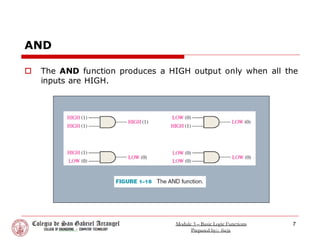
Basic Logic Functions
Module 3
1
Module 3 – Basic Logic Functions
Prepared by:; fscjr.
LCST – Logic Circuits and Switching Theory
Source: Digital Fundamentals by Floyd, T. 11th Edition
Introduction
 In its basic form, logic is the realm of human reasoning that
tells you a certain proposition (declarative statement) is true if
certain conditions are true.
 Propositions can be classified as true or false.
 Many situations and processes that you encounter in your daily
life can be expressed in the form of propositional, or logic,
functions.
 Since such functions are true/false or yes/no statements,
digital circuits with their two-state characteristics are
applicable.
2
Module 3 – Basic Logic Functions
Prepared by:; fscjr.
Learning Objectives
 After completing this module, the learners
should be able to:
1. List three basic logic functions
2. Define the NOT function
3. Define the AND function
4. Define the OR function
3
Module 3 – Basic Logic Functions
Prepared by:; fscjr.
Basic Logic Functions
 In the 1850s, the Irish logician and mathematician George
Boole developed a mathematical system for formulating logic
statements with symbols so that problems can be written and
solved in a manner similar to ordinary algebra.
 Boolean algebra, as it is known today, is applied in the design
and analysis of digital systems and will be covered in Chapter
4.
 The term logic is applied to digital circuits used to implement
logic functions.
 Several kinds of digital logic circuits are the basic elements
that form the building blocks for such complex digital systems
as the computer.
4
Module 3 – Basic Logic Functions
Prepared by:; fscjr.
Basic Logic Functions
 Three basic logic functions (NOT, AND, and OR) are indicated
by standard distinctive shape symbols
5
cont’d
Module 3 – Basic Logic Functions
Prepared by:; fscjr.
NOT
 The NOT function changes one logic level to the opposite logic
level.
 The NOT function is implemented by a logic circuit known as an
inverter.
6
Module 3 – Basic Logic Functions
Prepared by:; fscjr.
AND
 The AND function produces a HIGH output only when all the
inputs are HIGH.
7
Module 3 – Basic Logic Functions
Prepared by:; fscjr.
OR
 The OR function produces a HIGH output when one or more
inputs are HIGH.
8
Module 3 – Basic Logic Functions
Prepared by:; fscjr.
Mastery Exercises
9
1. When does the NOT function produce a HIGH output?
 When the input is LOW
2. When does the AND function produce a HIGH output?
 When all inputs are HIGH
3. When does the OR function produce a HIGH output?
 When any or all inputs are HIGH
4. What is an inverter?
 An inverter is a NOT circuit.
5. What is a logic gate?
 A logic gate is a circuit that performs a logic operation
(AND, OR).
Module 3 – Basic Logic Functions
Prepared by:; fscjr.

Module-3-Basic-Logic-Functions-PROF (1).pdf

  • 1.
    Basic Logic Functions Module3 1 Module 3 – Basic Logic Functions Prepared by:; fscjr. LCST – Logic Circuits and Switching Theory Source: Digital Fundamentals by Floyd, T. 11th Edition
  • 2.
    Introduction  In itsbasic form, logic is the realm of human reasoning that tells you a certain proposition (declarative statement) is true if certain conditions are true.  Propositions can be classified as true or false.  Many situations and processes that you encounter in your daily life can be expressed in the form of propositional, or logic, functions.  Since such functions are true/false or yes/no statements, digital circuits with their two-state characteristics are applicable. 2 Module 3 – Basic Logic Functions Prepared by:; fscjr.
  • 3.
    Learning Objectives  Aftercompleting this module, the learners should be able to: 1. List three basic logic functions 2. Define the NOT function 3. Define the AND function 4. Define the OR function 3 Module 3 – Basic Logic Functions Prepared by:; fscjr.
  • 4.
    Basic Logic Functions In the 1850s, the Irish logician and mathematician George Boole developed a mathematical system for formulating logic statements with symbols so that problems can be written and solved in a manner similar to ordinary algebra.  Boolean algebra, as it is known today, is applied in the design and analysis of digital systems and will be covered in Chapter 4.  The term logic is applied to digital circuits used to implement logic functions.  Several kinds of digital logic circuits are the basic elements that form the building blocks for such complex digital systems as the computer. 4 Module 3 – Basic Logic Functions Prepared by:; fscjr.
  • 5.
    Basic Logic Functions Three basic logic functions (NOT, AND, and OR) are indicated by standard distinctive shape symbols 5 cont’d Module 3 – Basic Logic Functions Prepared by:; fscjr.
  • 6.
    NOT  The NOTfunction changes one logic level to the opposite logic level.  The NOT function is implemented by a logic circuit known as an inverter. 6 Module 3 – Basic Logic Functions Prepared by:; fscjr.
  • 7.
    AND  The ANDfunction produces a HIGH output only when all the inputs are HIGH. 7 Module 3 – Basic Logic Functions Prepared by:; fscjr.
  • 8.
    OR  The ORfunction produces a HIGH output when one or more inputs are HIGH. 8 Module 3 – Basic Logic Functions Prepared by:; fscjr.
  • 9.
    Mastery Exercises 9 1. Whendoes the NOT function produce a HIGH output?  When the input is LOW 2. When does the AND function produce a HIGH output?  When all inputs are HIGH 3. When does the OR function produce a HIGH output?  When any or all inputs are HIGH 4. What is an inverter?  An inverter is a NOT circuit. 5. What is a logic gate?  A logic gate is a circuit that performs a logic operation (AND, OR). Module 3 – Basic Logic Functions Prepared by:; fscjr.