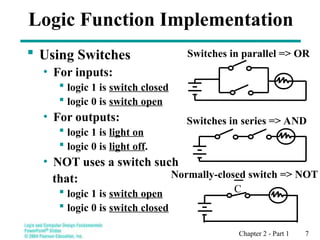
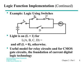
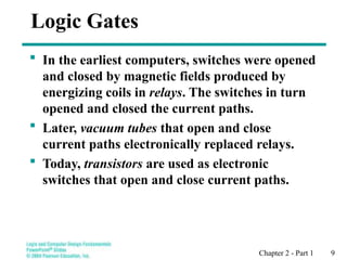
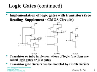
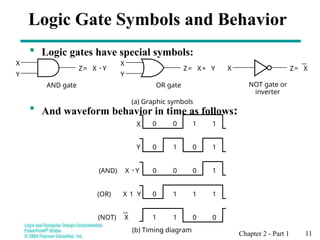
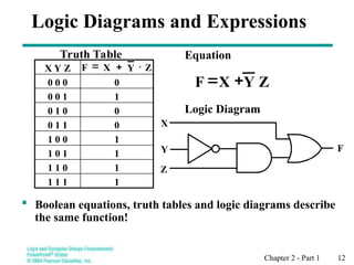
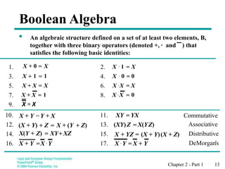
Chapter 2 - Part 1 1
Binary Logic and Gates
 Binary variables take on one of two values.
 Logical operators operate on binary values and
binary variables.
 Basic logical operators are the logic functions
AND, OR and NOT.
 Logic gates implement logic functions.
 Boolean Algebra: a useful mathematical system
for specifying and transforming logic functions.
 We study Boolean algebra as foundation for
designing and analyzing digital systems!
Chapter 2 - Part 1 2
Binary Variables
 Recall that the two binary values have
different names:
• True/False
• On/Off
• Yes/No
• 1/0
 We use 1 and 0 to denote the two values.
 Variable identifier examples:
• A, B, y, z, or X1 for now
• RESET, START_IT, or ADD1 later
Chapter 2 - Part 1 3
Logical Operations
 The three basic logical operations are:
• AND
• OR
• NOT
 AND is denoted by a dot (·).
 OR is denoted by a plus (+).
 NOT is denoted by an overbar ( ¯ ), a
single quote mark (') after, or (~) before
the variable.
Chapter 2 - Part 1 4
 Examples:
• is read “Y is equal to AAND B.”
• is read “z is equal to x OR y.”
• is read “X is equal to NOT A.”
Notation Examples
 Note: The statement:
1 + 1 = 2 (read “one plus one equals two”)
is not the same as
1 + 1 = 1 (read “1 or 1 equals 1”).
 B
A
Y 
y
x
z 

A
X 
Chapter 2 - Part 1 5
Operator Definitions
 Operations are defined on the values
"0" and "1" for each operator:
AND
0 · 0 = 0
0 · 1 = 0
1 · 0 = 0
1 · 1 = 1
OR
0 + 0 = 0
0 + 1 = 1
1 + 0 = 1
1 + 1 = 1
NOT
1
0
0
1
Chapter 2 - Part 1 6
0
1
1
0
X
NOT
X
Z
Truth Tables
 Truth table  a tabular listing of the values of a
function for all possible combinations of values on its
arguments
 Example: Truth tables for the basic logic operations:
1
1
1
0
0
1
0
1
0
0
0
0
Z = X·Y
Y
X
AND OR
X Y Z = X+Y
0 0 0
0 1 1
1 0 1
1 1 1
Chapter 2 - Part 1 7
 Using Switches
• For inputs:
 logic 1 is switch closed
 logic 0 is switch open
• For outputs:
 logic 1 is light on
 logic 0 is light off.
• NOT uses a switch such
that:
 logic 1 is switch open
 logic 0 is switch closed
Logic Function Implementation
Switches in series => AND
Switches in parallel => OR
C
Normally-closed switch => NOT
Chapter 2 - Part 1 8
 Example: Logic Using Switches
 Light is on (L = 1) for
L(A, B, C, D) =
and off (L = 0), otherwise.
 Useful model for relay circuits and for CMOS
gate circuits, the foundation of current digital
logic technology
Logic Function Implementation (Continued)
B
A
D
C
Chapter 2 - Part 1 9
Logic Gates
 In the earliest computers, switches were opened
and closed by magnetic fields produced by
energizing coils in relays. The switches in turn
opened and closed the current paths.
 Later, vacuum tubes that open and close
current paths electronically replaced relays.
 Today, transistors are used as electronic
switches that open and close current paths.
Chapter 2 - Part 1 10
Logic Gates (continued)
 Implementation of logic gates with transistors (See
Reading Supplement  CMOS Circuits)
 Transistor or tube implementations of logic functions are
called logic gates or just gates
 Transistor gate circuits can be modeled by switch circuits
•
F
+V
X
Y
+V
X
+V
X
Y
•
•
•
•
•
• •
•
• •
•
•
(a) NOR
G = X +Y
(b) NAND (c) NOT
X .Y
X
•
•
•
Chapter 2 - Part 1 11
Logic Gate Symbols and Behavior
 Logic gates have special symbols:
 And waveform behavior in time as follows:
(b) Timing diagram
X 0 0 1 1
Y 0 1 0 1
X · Y
(AND) 0 0 0 1
X 1 Y
(OR) 0 1 1 1
(NOT) X 1 1 0 0
(a) Graphic symbols
OR gate
X
Y
Z= X+ Y
X
Y
Z= X · Y
AND gate
X Z= X
NOT gate or
inverter
Chapter 2 - Part 1 12
Logic Diagrams and Expressions
 Boolean equations, truth tables and logic diagrams describe
the same function!
X
Y F
Z
Logic Diagram
Equation
Z
Y
X
F 

Truth Table
1
1 1 1
1
1 1 0
1
1 0 1
1
1 0 0
0
0 1 1
0
0 1 0
1
0 0 1
0
0 0 0
X Y Z Z
Y
X
F 


Chapter 2 - Part 1 13
1.
3.
5.
7.
9.
11.
13.
15.
17.
Commutative
Associative
Distributive
DeMorgan
’s
2.
4.
6.
8.
X .
1 X
=
X .
0 0
=
X .
X X
=
0
=
X .
X
Boolean Algebra
 An algebraic structure defined on a set of at least two elements, B,
together with three binary operators (denoted +, · and ) that
satisfies the following basic identities:
10.
12.
14.
16.
X + Y Y + X
=
(X + Y) Z
+ X + (Y Z)
+
=
X(Y + Z) XY XZ
+
=
X + Y X .
Y
=
XY YX
=
(XY)Z X(YZ)
=
X + YZ (X + Y)(X + Z)
=
X .
Y X + Y
=
X + 0 X
=
+
X 1 1
=
X + X X
=
1
=
X + X
X = X

new logic gates presentation basic gate universal gate.ppt

  • 1.
    Chapter 2 -Part 1 1 Binary Logic and Gates  Binary variables take on one of two values.  Logical operators operate on binary values and binary variables.  Basic logical operators are the logic functions AND, OR and NOT.  Logic gates implement logic functions.  Boolean Algebra: a useful mathematical system for specifying and transforming logic functions.  We study Boolean algebra as foundation for designing and analyzing digital systems!
  • 2.
    Chapter 2 -Part 1 2 Binary Variables  Recall that the two binary values have different names: • True/False • On/Off • Yes/No • 1/0  We use 1 and 0 to denote the two values.  Variable identifier examples: • A, B, y, z, or X1 for now • RESET, START_IT, or ADD1 later
  • 3.
    Chapter 2 -Part 1 3 Logical Operations  The three basic logical operations are: • AND • OR • NOT  AND is denoted by a dot (·).  OR is denoted by a plus (+).  NOT is denoted by an overbar ( ¯ ), a single quote mark (') after, or (~) before the variable.
  • 4.
    Chapter 2 -Part 1 4  Examples: • is read “Y is equal to AAND B.” • is read “z is equal to x OR y.” • is read “X is equal to NOT A.” Notation Examples  Note: The statement: 1 + 1 = 2 (read “one plus one equals two”) is not the same as 1 + 1 = 1 (read “1 or 1 equals 1”).  B A Y  y x z   A X 
  • 5.
    Chapter 2 -Part 1 5 Operator Definitions  Operations are defined on the values "0" and "1" for each operator: AND 0 · 0 = 0 0 · 1 = 0 1 · 0 = 0 1 · 1 = 1 OR 0 + 0 = 0 0 + 1 = 1 1 + 0 = 1 1 + 1 = 1 NOT 1 0 0 1
  • 6.
    Chapter 2 -Part 1 6 0 1 1 0 X NOT X Z Truth Tables  Truth table  a tabular listing of the values of a function for all possible combinations of values on its arguments  Example: Truth tables for the basic logic operations: 1 1 1 0 0 1 0 1 0 0 0 0 Z = X·Y Y X AND OR X Y Z = X+Y 0 0 0 0 1 1 1 0 1 1 1 1
  • 7.
    Chapter 2 -Part 1 7  Using Switches • For inputs:  logic 1 is switch closed  logic 0 is switch open • For outputs:  logic 1 is light on  logic 0 is light off. • NOT uses a switch such that:  logic 1 is switch open  logic 0 is switch closed Logic Function Implementation Switches in series => AND Switches in parallel => OR C Normally-closed switch => NOT
  • 8.
    Chapter 2 -Part 1 8  Example: Logic Using Switches  Light is on (L = 1) for L(A, B, C, D) = and off (L = 0), otherwise.  Useful model for relay circuits and for CMOS gate circuits, the foundation of current digital logic technology Logic Function Implementation (Continued) B A D C
  • 9.
    Chapter 2 -Part 1 9 Logic Gates  In the earliest computers, switches were opened and closed by magnetic fields produced by energizing coils in relays. The switches in turn opened and closed the current paths.  Later, vacuum tubes that open and close current paths electronically replaced relays.  Today, transistors are used as electronic switches that open and close current paths.
  • 10.
    Chapter 2 -Part 1 10 Logic Gates (continued)  Implementation of logic gates with transistors (See Reading Supplement  CMOS Circuits)  Transistor or tube implementations of logic functions are called logic gates or just gates  Transistor gate circuits can be modeled by switch circuits • F +V X Y +V X +V X Y • • • • • • • • • • • • (a) NOR G = X +Y (b) NAND (c) NOT X .Y X • • •
  • 11.
    Chapter 2 -Part 1 11 Logic Gate Symbols and Behavior  Logic gates have special symbols:  And waveform behavior in time as follows: (b) Timing diagram X 0 0 1 1 Y 0 1 0 1 X · Y (AND) 0 0 0 1 X 1 Y (OR) 0 1 1 1 (NOT) X 1 1 0 0 (a) Graphic symbols OR gate X Y Z= X+ Y X Y Z= X · Y AND gate X Z= X NOT gate or inverter
  • 12.
    Chapter 2 -Part 1 12 Logic Diagrams and Expressions  Boolean equations, truth tables and logic diagrams describe the same function! X Y F Z Logic Diagram Equation Z Y X F   Truth Table 1 1 1 1 1 1 1 0 1 1 0 1 1 1 0 0 0 0 1 1 0 0 1 0 1 0 0 1 0 0 0 0 X Y Z Z Y X F   
  • 13.
    Chapter 2 -Part 1 13 1. 3. 5. 7. 9. 11. 13. 15. 17. Commutative Associative Distributive DeMorgan ’s 2. 4. 6. 8. X . 1 X = X . 0 0 = X . X X = 0 = X . X Boolean Algebra  An algebraic structure defined on a set of at least two elements, B, together with three binary operators (denoted +, · and ) that satisfies the following basic identities: 10. 12. 14. 16. X + Y Y + X = (X + Y) Z + X + (Y Z) + = X(Y + Z) XY XZ + = X + Y X . Y = XY YX = (XY)Z X(YZ) = X + YZ (X + Y)(X + Z) = X . Y X + Y = X + 0 X = + X 1 1 = X + X X = 1 = X + X X = X

Editor's Notes

  • #8 L (A, B, C, D) = A ((B C') + D) = A B C' + A D Complementary metal–oxide–semiconductor = CMOS =  is a technology for constructing integrated circuits. أكسيد معدني متمم أشباه الموصلات
  • #9 energizing = making sth active. Coils = wires. vacuum tubes = أنابيب مفرغة
  • #10 The transistor without the “bubble” on its input is an N-type field effect transistor. It acts like a closed switch between its top and bottom terminals with an H (1) applied to its input on its left. It acts like an open switch with an L (0) applied to its input. The transistor with the “bubble” on its input is a P-type field effect transistor. The +V at the top provides an H (1) and the Ground symbol at the bottom provides an L (0). By modeling the two types of field effect transistors as switches, one can see how the series and parallel interconnections can produce 1’s and 0’s on the outputs on the right in response to applied 1’s and 0’s on the inputs on the left. NOR and NAND are OR and AND, each followed by a NOT respectively.