COMPUTER VISION (Module-4)
Dr.Ramesh Wadawadagi
Associate Professor
Department of CSE
SVIT, Bengaluru-560064
ramesh.sw@saividya.ac.in
Color Image Processing
Vignetting
How human eyesperceive different colors?
● The existence of three primary colors is a result of the
tristimulus (or trichromatic) nature of the human visual
system.
● Since we have three different kinds of cells called cone
cells, each of which responds selectively to a different
portion of the color spectrum.
Vignetting
Color properties:
● Threeproperties generally used to distinguish one color
from another are brightness, hue, and saturation.
● Brightness is achromatic notion (lightness or darkness) of
intensity, and is one of the key factors in describing color
sensation.
● Hue is an attribute associated with the dominant
wavelength in a mixture of light waves.
● Hue represents dominant color as perceived by an observer.
● Thus, when we call an object red, orange, or yellow, we are
referring to its Hue.
8.
Vignetting
Color properties:
● Saturationrefers to the relative purity or the amount of
white light mixed with a Hue.
● The pure spectrum colors are highly saturated.
● Colors such as pink (red and white) and lavender (violet
and white) are less saturated.
● The degree of saturation is measured as inversely
proportional to the amount of white light added.
● Hue and saturation taken together are called chromaticity
and, therefore, a color may be characterized by its
brightness and chromaticity.
9.
Tristimulus values:
● Theamounts of red, green, and blue required to form any
particular color are called the tristimulus values, and are
denoted, X, Y, and Z, respectively.
● A color is then specified by its trichromatic coefficients,
defined as:
Where x+y+z=1
10.
Color Models:
● Thepurpose of a color model (also called a color space or
color system) is to facilitate the specification of colors in
some standard way.
● In essence, a color model is a specification of
● (1) A coordinate system, and
● (2) A subspace within that system,
● Hence, each color in the model is represented by a single
point contained in that subspace.
● Different color models exists: RGB, CMY and HSI.
11.
Vignetting
The RGB ColorModel:
● In the RGB model, each color is represented as combination
of primary spectral components of red, green, and blue.
● This model is based on a Cartesian coordinate system in 3D
space.
RGB
Color cube
12.
The RGB ColorModel:
● In this model RGB primary values are at three corners;
● The secondary colors cyan, magenta, and yellow are at three
other corners;
● Black is at the origin; and white is at the corner farthest
from the origin.
● The grayscale (points of equal RGB values) extends from
black to white along the line joining these two points.
● Images represented in the RGB color model consist of three
component images, one for each primary color.
● The number of bits used to represent each pixel in RGB
space is called the pixel depth.
13.
The RGB ColorModel:
● Consider an RGB image in which each of the red, green,
and blue images is an 8-bit image.
● Under these conditions, each RGB color pixel has a depth
of 24 bits (3 image planes times the number of bits
perplane).
● The term full-color image is used often to denote a 24-bit
RGB color image.
● The total number of possible colors in a 24-bit RGB image
is (28
)3
= 16,777,216.
14.
The CMY andCMYB Color Model:
● Cyan, Magenta, and Yellow are the secondary colors of
light.
● RGB to CMY conversion can be done internally using the
simple operation.
● In order to produce true black (which is the predominant
color in printing), a fourth color, black, denoted by K, is
added, giving rise to the CMYK color model.
15.
The CMY andCMYB Color Model:
● The conversion from CMY to CMYK begins by letting
K = min(C, M, Y ).
● If K = 1, then we have pure black, with no color
contributions, from which it follows that C=0, M=0,
Y=0.
● Otherwise,
C = (C − K ) (1 − K )
M = (M − K ) (1 − K )
Y = (Y − K ) (1 − K )
where all values are assumed to be in the range [0, 1].
16.
The CMY andCMYB Color Model:
● The conversions from CMYK back to CMY are:
C = C * (1 − K ) + K
M = M * (1 − K ) + K
Y = Y * (1 − Y ) + K
17.
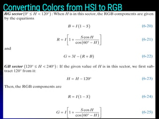
THE HSI COLORMODEL
● When humans view a color object, we describe it by its
hue, saturation, and brightness.
● Hue is a color attribute that describes a pure color
(pure yellow, orange, or red).
● Saturation gives a measure of the degree to which a
pure color is diluted by white light.
● Brightness is a subjective descriptor that is practically
impossible to measure.
● It embodies the achromatic notion of intensity and is
one of the key factors in describing color sensation.
18.
THE HSI COLORMODEL
● However, Intensity (gray level) is a most useful
descriptor of achromatic images.
● This quantity definitely is measurable and easily
interpretable.
● The model we are about to present, called the HSI
(hue, saturation, intensity) color model, decouples the
intensity component from the color-carrying
information (hue and saturation) in a color image.
● The HSI model is a useful tool for developing image
processing algorithms based on color descriptions that
are natural and intuitive to humans.
Intensity
● The intensitycan be modeled along the line joining the
black and white vertices of RGB model in Figure 6.10.
21.
Intensity
● In Figs.6.10(a) and (b), the line (intensity axis) joining
the black and white vertices is vertical.
● Thus, if we wanted to determine the intensity
component of any color point in Fig. 6.10, we would
simply define a plane that contains the color point and,
at the same time, is perpendicular to the intensity axis.
● The intersection of the plane with the intensity axis
would give us a point with intensity value in the range
[0, 1].
22.
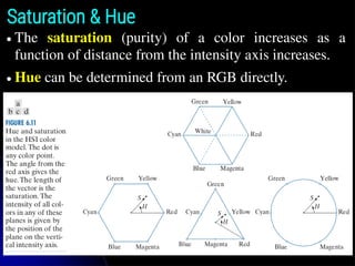
Saturation & Hue
●The saturation (purity) of a color increases as a
function of distance from the intensity axis increases.
● Hue can be determined from an RGB directly.
PSEUDOCOLOR IMAGE PROCESSING
●Pseudocolor (sometimes called false color) image
processing consists of assigning colors to gray values
based on a specified criterion.
● The principal use of pseudocolor is for human
visualization and interpretation of grayscale events in
an image or sequence of images.
INTENSITY SLICING AND COLOR CODING
PSEUDOCOLOR IMAGE PROCESSING
● The techniques of intensity (sometimes called density)
slicing and color coding are the simplest and earliest
examples of pseudocolor processing of digital images.
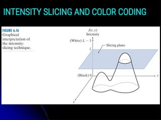
27.
● If animage is interpreted as a 3-D function, the method
can be viewed as one of placing planes parallel to the
coordinate plane of the image; each plane then “slices”
the function in the area of intersection.
● Figure 6.16 shows an example of using a plane at
f(x, y) = li to slice the image intensity function into two
levels.
● If a different color is assigned to each side of the plane
in Fig. 6.16, any pixel whose intensity level is above the
plane will be coded with one color, and any pixel
below the plane will be coded with the other.
INTENSITY SLICING AND COLOR CODING
● Levels thatlie on the plane itself may be arbitrarily
assigned one of the two colors, or they could be given a
third color to highlight all the pixels at that level.
● The result is a two- (or three-) color image whose
relative appearance can be controlled by moving the
slicing plane up and down the intensity axis.
● In general, the technique for multiple colors may be
summarized as follows:
● Let [0, L−1] represent the grayscale, let level l0
represent black [f(x, y) = 0], and level lL−1 represent
white [f(x, y) = L − 1].
INTENSITY SLICING AND COLOR CODING
30.
● Suppose thatP planes perpendicular to the intensity
axis are defined at levels l1, l2, …, lP.
● Then, assuming that 0 < P < L−1, the P planes
partition the grayscale into P+1 intervals, I1, I2,…, IP+1.
● Intensity to color assignments at each pixel location
(x, y) are made according to the equation
if f(x, y) ∈ Ik, let f(x, y) = ck
● Where ck is the color associated with the kth
intensity
interval Ik, defined by the planes at l = k−1 and l = k.
INTENSITY SLICING AND COLOR CODING
● Other typesof transformations are more general, and
thus are capable of achieving a wider range of
pseudocolor enhancement results than the simple
slicing technique discussed in the preceding section.
● Figure 6.21 shows an approach that is particularly
attractive.
● Basically, the idea underlying this approach is to
perform three independent transformations on the
intensity of input pixels.
● The three results are then fed separately into the red,
green, and blue channels of a color monitor.
INTENSITY TO COLOR TRANSFORMATIONS
● This methodproduces a composite image whose color
content is modulated by the nature of the
transformation functions.
● Piecewise linear functions of the intensity levels (see
Fig. 6.17) are used to generate colors.
● On the other hand, the method can be based on
smooth, nonlinear functions, which gives the
technique considerable flexibility.
● The approach in Fig. 6.21 is based on a single grayscale
image.
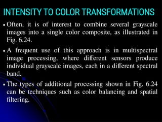
INTENSITY TO COLOR TRANSFORMATIONS
37.
● Often, itis of interest to combine several grayscale
images into a single color composite, as illustrated in
Fig. 6.24.
● A frequent use of this approach is in multispectral
image processing, where different sensors produce
individual grayscale images, each in a different spectral
band.
● The types of additional processing shown in Fig. 6.24
can be techniques such as color balancing and spatial
filtering.
INTENSITY TO COLOR TRANSFORMATIONS
INTENSITY TO COLORTRANSFORMATIONS
(a)–(d) Red (R), green (G), blue (B), and near-infrared (IR) components of a LANDSAT multispectral image of the
Washington, D.C. area. (e) RGB color composite image obtained using the IR, G, and B component images. (f) RGB
color composite image obtained using the R, IR, and B component images.
40.
● Let crepresent an arbitrary vector in RGB color space:
● This equation indicates that the components of c are the
RGB components of a color image at a point (x, y).
● We take into account the fact that the colors of the pixels in
an image are a function of spatial coordinates (x, y) by
using the notation.
FULL-COLOR IMAGE PROCESSING
41.
● Full-color imageprocessing approaches fall into two
major categories.
● In the first category, we process each grayscale
component image individually, then form a composite
color image from the individually processed
components.
● In the second category, we work with color pixels
directly.
● Because full-color images have at least three
components, color pixels are vectors.
FULL-COLOR IMAGE PROCESSING
42.
FULL-COLOR IMAGE PROCESSING
●For an image of size M × N, there are MN such vectors,
c(x, y), for x = 0, 1, 2, … , M−1 and y = 0, 1, 2, … , N−1.
● The above equation depicts a vector whose components are
spatial variables x and y.
● Color transformationsdeal with processing the components
of a color image within the context of a single color model,
as opposed to color transformations between color model.
COLOR TRANSFORMATIONS
FORMULATION
● We model color transformations for multispectral images
using the general expression.
si = Ti (ri) i = 1, 2,…, n
● Where n is the total number of component images, ri are
the intensity values of the input component images, si are
the spatially corresponding intensities in the output
component images, and Ti are a set of transformation or
color mapping functions that operate on ri to produce si.
45.
● The aboveequation is applied individually to all pixels in
the input image.
● For example, in the case of RGB color images, n = 3, r1,
r2, r3 are the intensities values at a point in the input
components images, and s1, s2, s3 are the corresponding
transformed pixels in the output image.
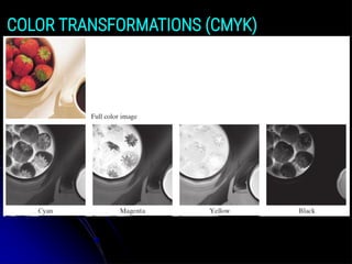
● As an illustration, the first row of Fig. 6.28 shows a full
color CMYK image of a simple scene, and the second row
shows its four component images, all normalized to the
range [0, 1].
● We see that the strawberries are composed of large amounts
of magenta and yellow because the images corresponding to
these two CMYK components are the brightest.
COLOR TRANSFORMATIONS
46.
● We canapply Eq. (6-38) to any of the color-space
component images in Fig. 6.28.
● In the HSI color space we need to modify only the intensity
component image:
s3 = kr3
● and we let s1 = r1 and s2 = r2. In terms of our earlier
discussion note that we are using two different
transformation functions: T1 and T2 are identity
transformations, and T3 is a constant transformation.
● In the RGB color space we need to modify all three
components by the same constant transformation:
si = kri i = 1, 2, 3
COLOR TRANSFORMATIONS


![The CMY and CMYB Color Model:
● The conversion from CMY to CMYK begins by letting
K = min(C, M, Y ).
● If K = 1, then we have pure black, with no color
contributions, from which it follows that C=0, M=0,
Y=0.
● Otherwise,
C = (C − K ) (1 − K )
M = (M − K ) (1 − K )
Y = (Y − K ) (1 − K )
where all values are assumed to be in the range [0, 1].](https://image.slidesharecdn.com/module-4colorimageprocessing-250417041100-eb5a88dd/85/Module-4-Color-Image-Processing-techniques-15-320.jpg)


![Intensity
● In Figs. 6.10(a) and (b), the line (intensity axis) joining
the black and white vertices is vertical.
● Thus, if we wanted to determine the intensity
component of any color point in Fig. 6.10, we would
simply define a plane that contains the color point and,
at the same time, is perpendicular to the intensity axis.
● The intersection of the plane with the intensity axis
would give us a point with intensity value in the range
[0, 1].](https://image.slidesharecdn.com/module-4colorimageprocessing-250417041100-eb5a88dd/85/Module-4-Color-Image-Processing-techniques-21-320.jpg)


![● Levels that lie on the plane itself may be arbitrarily
assigned one of the two colors, or they could be given a
third color to highlight all the pixels at that level.
● The result is a two- (or three-) color image whose
relative appearance can be controlled by moving the
slicing plane up and down the intensity axis.
● In general, the technique for multiple colors may be
summarized as follows:
● Let [0, L−1] represent the grayscale, let level l0
represent black [f(x, y) = 0], and level lL−1 represent
white [f(x, y) = L − 1].
INTENSITY SLICING AND COLOR CODING](https://image.slidesharecdn.com/module-4colorimageprocessing-250417041100-eb5a88dd/85/Module-4-Color-Image-Processing-techniques-29-320.jpg)


![● The above equation is applied individually to all pixels in
the input image.
● For example, in the case of RGB color images, n = 3, r1,
r2, r3 are the intensities values at a point in the input
components images, and s1, s2, s3 are the corresponding
transformed pixels in the output image.
● As an illustration, the first row of Fig. 6.28 shows a full
color CMYK image of a simple scene, and the second row
shows its four component images, all normalized to the
range [0, 1].
● We see that the strawberries are composed of large amounts
of magenta and yellow because the images corresponding to
these two CMYK components are the brightest.
COLOR TRANSFORMATIONS](https://image.slidesharecdn.com/module-4colorimageprocessing-250417041100-eb5a88dd/85/Module-4-Color-Image-Processing-techniques-45-320.jpg)