MODULE 02 - CLOUD COMPUTING-Virtual Machines and Virtualization of Clusters and Data Centers.pptx
1.
Module 2
Virtual Machinesand
Virtualization of
Clusters and Data
Centers
Prepared by,
Mrs. Vidya
Senior Assistant Professor
Department of CSE,AIET
1
2.
SUMMARY
2
• The reincarnationof virtual machines (VMs) presents a great
opportunity for parallel, cluster, grid, cloud, and distributed
computing.
• Virtualization technology benefits the computer and IT industries
by enabling users to share expensive hardware resources by
multiplexing VMs on the same set of hardware hosts.
• This chapter covers virtualization levels, VM architectures,
virtual networking, virtual cluster construction, and virtualized
data-center design and automation in cloud computing.
• In particular, the designs of dynamically structured clusters, grids,
and clouds are presented with VMs and virtual clusters.
3.
3.1 IMPLEMENTATION LEVELSOF VIRTUALIZATION
3
• Virtualization is a computer architecture technology by
which multiple virtual machines (VMs) are multiplexed in
the same hardware machine.
• The idea of VMs can be dated back to the 1960s. The
purpose of a VM is to
enhance resource sharing by many users and improve
computer performance in terms of resource utilization
and application flexibility.
• Hardware resources (CPU, memory, I/O devices, etc.) or
software resources (operating system and software libraries)
can be virtualized in various functional layers.
• This virtualization technology has been revitalized as the
demand for distributed and cloud computing increased
sharply in recent years .
4.
3.1.1 Levels ofVirtualization Implementation
4
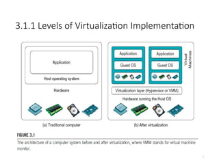
• A traditional computer runs with a host operating system specially tailored for its
hardware architecture, as shown in Figure 3.1(a).
• After virtualization, different user applications managed by their own operating
systems (guest OS) can run on the same hardware, independent of the host OS.
• This is often done by adding additional software, called a virtualization layer as
shown in Figure 3.1(b).
• This virtualization layer is known as hypervisor or virtual machine monitor (VMM)
[54]. The VMs are shown in the upper boxes, where applications run with their
own guest OS over the virtualized CPU, memory, and I/O resources.
• The main function of the software layer for virtualization is to virtualize the
physical hardware of a host machine into virtual resources to be used by the VMs,
exclusively.
• This can be implemented at various operational levels, as we will discuss shortly.
2.1.2 Design Objectivesof Computer Clusters
6
• The virtualization software creates the
abstraction of VMs by
interposing a virtualization layer at
various levels of a computer
system.
• Common virtualization layers include
the instruction set architecture
(ISA) level, hardware level,
operating system level,
library support level, and
application level.
7.
3.1.1.1 Instruction SetArchitecture Level
7
• At the ISA level, virtualization is performed by emulating a given ISA by the ISA
of the host machine.
• For example, MIPS binary code can run on an x86-based host machine with
the help of ISA emulation. With this approach, it is possible to run a
large amount of legacy binary code written for various processors on any
given new hardware host machine. Instruction set emulation
leads to virtual ISAs created on any hardware machine.
• The basic emulation method is through code interpretation. An interpreter
program interprets the source instructions to target instructions one by
one. One source instruction may require tens or hundreds of
native target instructions to perform its function. Obviously, this process
is relatively slow.
• For better performance, dynamic binary translation is desired. This approach
translates basic blocks of dynamic source instructions to target instructions.
• A virtual instruction set architecture (V-ISA) thus requires adding a processor-
specific software translation layer to the compiler.
8.
3.1.1.2 Hardware AbstractionLevel
• Hardware-level virtualization is performed right on top of the
bare hardware.
• On the one hand, this approach generates a virtual hardware
environment for a VM. The process manages the
underlying hardware through virtualization.
• The idea is to virtualize a computer’s resources, such as its
processors, memory, and I/O devices.
• The intention is to upgrade the hardware utilization rate by
multiple
• users concurrently.
• The idea was implemented in the IBM VM/370 in the 1960s.
More recently, the Xen hypervisor has been applied to virtualize
x86-based machines to run Linux or other guest OS
applications.
• We will discuss hardware virtualization approaches in more 8
9.
3.1.1.3 Operating SystemLevel
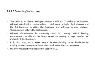
• This refers to an abstraction layer between traditional OS and user applications.
OS-level virtualization creates isolated containers on a single physical server and
the OS instances to utilize the hardware and software in data centers.
The containers behave like real servers.
• OS-level virtualization is commonly used in creating virtual hosting
environments to allocate hardware resources among a large number of
mutually distrusting users.
• It is also used, to a lesser extent, in consolidating server hardware by
moving services on separate hosts into containers or VMs on one server.
• OS-level virtualization is depicted in Section 3.1.3.
9
10.
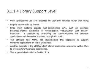
3.1.1.4 Library SupportLevel
• Most applications use APIs exported by user-level libraries rather than using
• lengthy system calls by the OS.
• Since most systems provide well-documented APIs, such an interface
becomes another candidate for virtualization. Virtualization with library
interfaces is possible by controlling the communication link between
applications and the rest of a system through API hooks.
• The software tool WINE has implemented this approach to support
Windows applications on top of UNIX hosts.
• Another example is the vCUDA which allows applications executing within VMs
to leverage GPU hardware acceleration.
• This approach is detailed in Section 3.1.4.
10
11.
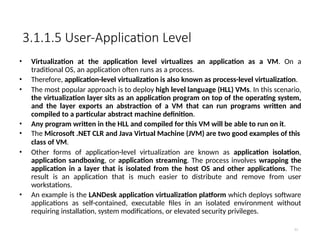
3.1.1.5 User-Application Level
11
•Virtualization at the application level virtualizes an application as a VM. On a
traditional OS, an application often runs as a process.
• Therefore, application-level virtualization is also known as process-level virtualization.
• The most popular approach is to deploy high level language (HLL) VMs. In this scenario,
the virtualization layer sits as an application program on top of the operating system,
and the layer exports an abstraction of a VM that can run programs written and
compiled to a particular abstract machine definition.
• Any program written in the HLL and compiled for this VM will be able to run on it.
• The Microsoft .NET CLR and Java Virtual Machine (JVM) are two good examples of this
class of VM.
• Other forms of application-level virtualization are known as application isolation,
application sandboxing, or application streaming. The process involves wrapping the
application in a layer that is isolated from the host OS and other applications. The
result is an application that is much easier to distribute and remove from user
workstations.
• An example is the LANDesk application virtualization platform which deploys software
applications as self-contained, executable files in an isolated environment without
requiring installation, system modifications, or elevated security privileges.
12.
3.1.1.6 Relative Meritsof Different Approaches
12
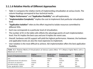
• Table 3.1 compares the relative merits of implementing virtualization at various levels. The
column headings correspond to four technical merits.
• “Higher Performance” and “Application Flexibility” are self-explanatory.
• “Implementation Complexity” implies the cost to implement that particular virtualization
level.
• “Application Isolation” refers to the effort required to isolate resources committed to
different VMs.
• Each row corresponds to a particular level of virtualization.
• The number of X’s in the table cells reflects the advantage points of each implementation
level. Five X’s implies the best case and one X implies the worst case.
• Overall, hardware and OS support will yield the highest performance. However, the hardware
and application levels are also the most expensive to implement.
• User isolation is the most difficult to achieve. ISA implementation offers the best application
flexibility.
13.
3.1.2 VMM DesignRequirements and Providers
13
• As mentioned earlier, hardware-level virtualization inserts a layer between
real hardware and traditional operating systems. This layer is commonly
called the Virtual Machine Monitor (VMM) and it manages the
hardware resources of a computing system.
• Each time programs access the hardware, the VMM captures the process. In this
sense, the VMM acts as a traditional OS. One hardware component, such as the
CPU, can be virtualized as several virtual copies. Therefore, several traditional
operating systems which are the same or different can sit on the same set of
hardware simultaneously.
• There are three requirements for a VMM.
• First, a VMM should provide an environment for programs which is essentially
identical to the original machine.
• Second, programs run in this environment should show, at worst, only minor
decreases in speed.
• Third, a VMM should be in complete control of the system resources. Any
program run under a VMM should exhibit a function identical to that which it
runs on the original machine directly.
14.
• Two possibleexceptions in terms of differences are permitted
with this requirement:
• 1) differences caused by the availability of system resources .
This one arises when more than one VM is running on the
same machine. The hardware resource requirements, such as
memory, of each VM are reduced, but the sum of them is
greater than that of the real machine installed.
• 2) differences caused by timing dependencies. This
qualification is required because of the intervening level of
software and the effect of any other VMs concurrently existing
on the same hardware.
3.1.2 VMM Design Requirements and Providers
15.
3.1.2 VMM DesignRequirements and Providers
15
• Obviously, these two differences pertain to performance,
while the function a VMM provides stays the same as that of a
real machine.
• A VMM should demonstrate efficiency in using the VMs.
Compared with a physical machine, no one prefers a VMM if its
efficiency is too low.
• Traditional emulators and complete software interpreters
(simulators) emulate each instruction by means of functions
or macros. Such a method provides the most flexible
solutions for VMMs. However, emulators or simulators are
too slow to be used as real machines.
• To guarantee the efficiency of a VMM, a statistically dominant
subset of the virtual processor’s instructions needs to be
executed directly by the real processor, with no software
intervention by the VMM.
16.
3.1.2 VMM DesignRequirements and Providers
16
• Table 3.2 compares four hypervisors and VMMs that are in use today.
17.
3.1.2 VMM DesignRequirements and Providers
17
• Complete control of these resources by a VMM includes the following aspects:
• (1) The VMM is responsible for allocating hardware resources for programs;
• (2) It is not possible for a program to access any resource not explicitly
allocated to it;
• (3) It is possible under certain circumstances for a VMM to regain control of
resources already allocated.
• Not all processors satisfy these requirements for a VMM. A VMM is tightly
related to the architectures of processors. It is difficult to implement a VMM for
some types of processors, such as the x86. Specific limitations include
the inability to trap on some privileged instructions.
• If a processor is not designed to support virtualization primarily, it is necessary to
modify the hardware to satisfy the three requirements for a VMM. This is known
as hardware-assisted virtualization.
18.
3.1.3 Virtualization Supportat the OS
Level
18
• With the help of VM technology, a new computing mode
known as cloud computing is emerging.
• Cloud computing is transforming the computing landscape by
shifting the hardware and staffing costs of managing a
computational center to third parties, just like banks.
• However, cloud computing has at least two challenges.
• The first challenge is the ability to use a variable number of
physical machines and VM instances depending on the needs of a
problem. For example, a task may need only a single CPU during
some phases of execution but may need hundreds of CPUs at other
times.
• The second challenge concerns the slow operation of
instantiating new VMs. Currently, new VMs originate either as fresh
boots or as replicates of a template VM, unaware of the current
application state. Therefore, to better support cloud computing, a
large amount of research and development should be done.
19.
19
3.1.3 Virtualization Supportat the OS Level
• As mentioned earlier, it is slow to initialize a hardware-
level VM because each VM creates its own image from
scratch.
• In a cloud computing environment, perhaps thousands
of VMs need to be initialized simultaneously.
• Besides slow operation, storing the VM images
also becomes an issue. As a matter of fact, there is
considerable repeated content among VM images.
• Moreover, full virtualization at the hardware level also
has the disadvantages of slow performance and low
density, and the need for para-virtualization to modify
the guest OS.
• To reduce the performance overhead of hardware-
level virtualization, even hardware modification is needed.
20.
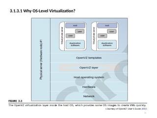
3.1.3.1 Why OS-LevelVirtualization?
20
• OS-level virtualization provides a feasible solution for these hardware-level
virtualization issues.
• Operating system virtualization inserts a virtualization layer inside an operating
system to partition a machine’s physical resources.
• It enables multiple isolated VMs within a single operating system kernel. This
kind of VM is often called a virtual execution environment (VE), Virtual Private
System (VPS), or simply container.
• From the user’s point of view, VEs look like real servers.
• This means a VE has its own set of processes, file system, user accounts, network
interfaces with IP addresses, routing tables, firewall rules, and other personal
settings.
• Although VEs can be customized for different people, they share the same operating
system
kernel. Therefore, OS-level virtualization is also called single-OS image virtualization.
• Figure 3.3 illustrates operating system virtualization from the point of view of a
machine stack.
3.1.3.2 Advantages ofOS Extensions
22
• Compared to hardware-level virtualization, the benefits of OS extensions are
twofold:
• (1) VMs at the operating system level have minimal startup/shutdown costs, low
resource requirements, and high scalability;
• (2) for an OS-level VM, it is possible for a VM and its host environment to
synchronize state changes when necessary.
• These benefits can be achieved via two mechanisms of OS-level virtualization:
• (1) All OS-level VMs on the same physical machine share a single operating
system kernel;
• (2) the virtualization layer can be designed in a way that allows processes in VMs to
access as many resources of the host machine as possible.
• In cloud computing, the first and second benefits can be used to
overcome the defects of slow initialization of VMs at the hardware
level, and being unaware of the current application state,
respectively.
23.
3.1.3.3 Disadvantages ofOS Extensions
23
• The main disadvantage of OS extensions is that all the VMs at operating system level
on a single container must have the same kind of guest operating system. That is,
although different OS-level VMs may have different operating system distributions,
they must pertain to the same operating system family.
• For example, a Windows distribution such as Windows XP cannot run on a Linux- based
container. However, users of cloud computing have various preferences. Some prefer
Windows and others prefer Linux or other operating systems. Therefore, there is a
challenge for OS-level virtualization in such cases.
• Figure 3.3 illustrates the concept of OS-level virtualization. The virtualization layer is
inserted inside the OS to partition the hardware resources for multiple VMs to run their
applications in multiple virtual environments. To implement OS-level virtualization,
isolated execution environments (VMs) should be created based on a single OS kernel.
• Furthermore, the access requests from a VM need to be redirected to the VM’s local
resource partition on the physical machine. For example, the chroot command
in a UNIX system can create several virtual root directories within a host OS.
24.
24
3.1.3.4 Virtualization onLinux or Windows Platforms
• By far, most reported OS-level virtualization systems are Linux-based.
Virtualization support on the Windows-based platform is still in the
research stage. The Linux kernel offers an abstraction layer to allow
software processes to work with and operate on resources without
knowing the hardware details.
• New hardware may need a new Linux kernel to support. Therefore,
different Linux platforms use patched kernels to provide special support
for extended functionality. However, most Linux platforms are not tied to a
special kernel. In such a case, a host can run several VMs simultaneously
on the same hardware.
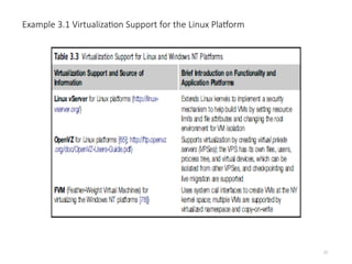
• Table 3.3 summarizes several examples of Oslevel virtualization tools that
have been developed in recent years. Two OS tools (Linux vServer and
OpenVZ) support Linux platforms to run other platform-based applications
through virtualization. These two OS-level tools are illustrated in Example
3.1.
• The third tool, FVM, is an attempt specifically developed for virtualization
on the Windows NT platform.
26
3.2 VIRTUALIZATION STRUCTURES/TOOLSAND MECHANISMS
In general, there are three typical classes of VM architecture.
Figure 3.1 showed the architectures of a machine before and after
virtualization.
• Before virtualization, the operating system manages the hardware.
After virtualization, a virtualization layer is inserted between the
hardware and the operating system.
• In such a case, the virtualization layer is responsible for
converting portions of the real hardware into virtual hardware.
Therefore, different operating systems such as Linux and
Windows can run on the same physical machine, simultaneously.
• Depending on the position of the virtualization layer, there are
several classes of VM architectures, namely the hypervisor
architecture, para- virtualization, and host-based virtualization.
• The hypervisor is also known as the VMM (Virtual Machine
Monitor). They both perform the same virtualization operations.
27.
27
1. Hypervisor andXen Architecture
• The hypervisor supports hardware-level virtualization (see Figure
3.1(b)) on devices like CPU, memory, disk and network interfaces.
• The hypervisor software sits directly between the physical hardware
and its OS.
• The hypervisor provides hyper-calls for the guest OSes and
applications.
• Depending on the functionality, a hypervisor can assume a micro-
kernel architecture like the Microsoft Hyper-V. Or it can assume a
monolithic hypervisor architecture like the VMware ESX for server
virtualization.
• A micro-kernel hypervisor includes only the basic and unchanging
functions (such as physical memory management and processor
scheduling). The device drivers and other changeable
components are outside the hypervisor.
• A monolithic hypervisor implements all the aforementioned
functions, including those of the device drivers. Therefore, the size
of the hypervisor code of a micro-kernel hypervisor is smaller than
that of a monolithic hypervisor.
• Essentially, a hypervisor must be able to convert physical devices
into virtual resources dedicated for the deployed VM to use.
29.
29
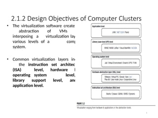
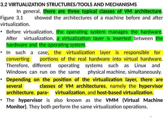
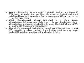
1. The XenArchitecture
• Xen is an open source hypervisor program developed by
Cambridge University.
• Xen is a microkernel hypervisor, which separates the policy from the
mechanism.
• The Xen hypervisor implements all the mechanisms, leaving the policy to
be handled by Domain 0, as shown in Figure 3.5.
• Xen does not include any device drivers natively [7]. It just provides a
mechanism by which a guest OS can have direct access to the
physical devices. As a result, the size of the Xen hypervisor is kept rather
small.
• Xen provides a virtual environment located between the hardware and
the OS.
• A number of vendors are in the process of developing commercial Xen
hypervisors, among them are Citrix XenServer [62] and Oracle VM [42].
• The core components of a Xen system are the hypervisor, kernel, and
applications. The organization of the three components is important.
30.
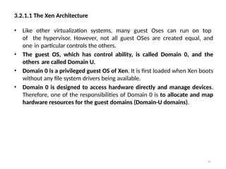
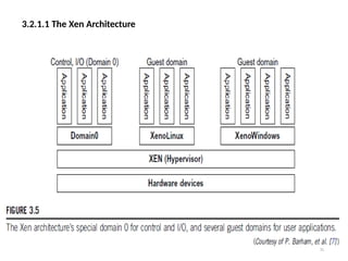
3.2.1.1 The XenArchitecture
30
• Like other virtualization systems, many guest Oses can run on top
of the hypervisor. However, not all guest OSes are created equal, and
one in particular controls the others.
• The guest OS, which has control ability, is called Domain 0, and the
others are called Domain U.
• Domain 0 is a privileged guest OS of Xen. It is first loaded when Xen boots
without any file system drivers being available.
• Domain 0 is designed to access hardware directly and manage devices.
Therefore, one of the responsibilities of Domain 0 is to allocate and map
hardware resources for the guest domains (Domain-U domains).
3.2.2 Binary Translationwith Full
Virtualization
32
• Depending on implementation technologies, hardware
virtualization can be classified into two categories:
• FULL VIRTUALIZATION AND HOST-BASED VIRTUALIZATION.
• hypervisor and VMM approaches are considered full virtualization
• Full virtualization does not need to modify the host OS. It
relies on binary translation to trap and to virtualize the
execution of certain sensitive, non-virtualizable instructions.
The guest OSes and their applications consist of non-critical and
critical instructions.
• In a host-based system, both a host OS and a guest OS are used. A
virtualization software layer is built between the host OS and guest
OS.
33.
3.2.2.1 Full Virtualization
33
•With full virtualization, noncritical instructions run on the
hardware directly while critical instructions are discovered
and replaced with traps into the VMM to be emulated by
software.
• Why are only critical instructions trapped into the VMM?
This is because binary translation can incur a large
performance overhead. Noncritical instructions do not
control hardware or threaten the security of the
system, but critical instructions do.
• Therefore, running noncritical instructions on hardware not
only can promote efficiency, but also can ensure system
security.
34.
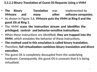
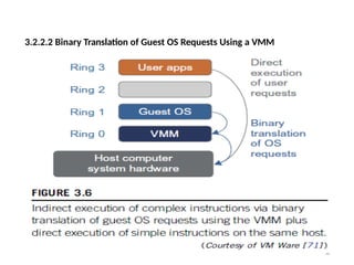
3.2.2.2 Binary Translationof Guest OS Requests Using a VMM
34
• The Binary Translation was implemented by
VMware and many other software companies.
• As shown in Figure 3.6, VMware puts the VMM at Ring 0 and the
guest OS at Ring 1.
• The VMM scans the instruction stream and identifies the
privileged, control- and behavior-sensitive instructions.
• When these instructions are identified, they are trapped into the
VMM, which emulates the behavior of these instructions.
• The method used in this emulation is called binary translation.
• Therefore, full virtualization combines binary translation and direct
execution.
• The guest OS is completely decoupled from the underlying
hardware. Consequently, the guest OS is unaware that it is being
virtualized.
35.
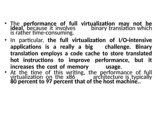
• The performanceof full virtualization may not be
ideal, because it involves binary translation which
is rather time-consuming.
• In particular, the full virtualization of I/O-intensive
applications is a really a big challenge. Binary
translation employs a code cache to store translated
hot instructions to improve performance, but it
increases the cost of memory usage.
• At the time of this writing, the performance of full
virtualization on the x86 architecture is typically
80 percent to 97 percent that of the host machine..
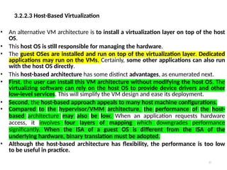
3.2.2.3 Host-Based Virtualization
37
•An alternative VM architecture is to install a virtualization layer on top of the host
OS.
• This host OS is still responsible for managing the hardware.
• The guest OSes are installed and run on top of the virtualization layer. Dedicated
applications may run on the VMs. Certainly, some other applications can also run
with the host OS directly.
• This host-based architecture has some distinct advantages, as enumerated next.
• First, the user can install this VM architecture without modifying the host OS. The
virtualizing software can rely on the host OS to provide device drivers and other
low-level services. This will simplify the VM design and ease its deployment.
• Second, the host-based approach appeals to many host machine configurations.
• Compared to the hypervisor/VMM architecture, the performance of the host-
based architecture may also be low. When an application requests hardware
access, it involves four layers of mapping which downgrades performance
significantly. When the ISA of a guest OS is different from the ISA of the
underlying hardware, binary translation must be adopted.
• Although the host-based architecture has flexibility, the performance is too low
to be useful in practice.
38.
3.2.3 Para-Virtualization withCompiler Support
38
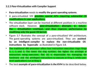
• Para-virtualization needs to modify the guest operating systems.
• A para-virtualized VM provides special APIs requiring substantial OS
modifications in user applications.
• The virtualization layer can be inserted at different positions in a machine
software stack. However, para-virtualization attempts to reduce
the virtualization overhead, and thus improve performance by
modifying only the guest OS kernel.
• Figure 3.7 illustrates the concept of a para-virtualized VM architecture.
The guest operating systems are para-virtualized. They are assisted
by an intelligent compiler to replace the non-virtualizable OS
instructions by hypercalls as illustrated in Figure 3.8.
• The traditional x86 processor offers four instruction execution rings: Rings
0, 1, 2, and 3. The lower the ring number, the higher the privilege of
instruction being executed. The OS is responsible for managing the
hardware and the privileged instructions to execute at Ring 0, while user-
level applications run at Ring 3.
• The best example of para-virtualization is the KVM to be described below.
3.2.3 Para-Virtualization withCompiler Support
40
• Although para-virtualization reduces the overhead, it has incurred
other problems.
• First, its compatibility and portability may be in doubt, because it
must support the unmodified OS as well.
• Second, the cost of maintaining para-virtualized OSes is high,
because they may require deep OS kernel modifications.
• Finally, the performance advantage of para-virtualization varies
greatly due to workload variations.
• Compared with full virtualization, para-virtualization is relatively
easy and more practical.
• The main problem in full virtualization is its low performance in
binary translation. To speed up binary translation is difficult.
Therefore, many virtualization products employ the para-
virtualization architecture. The popular Xen, KVM, and VMware
ESX are good examples.
41.
41
3.2.3 Para-Virtualization withCompiler Support
KVM (Kernel-Based VM)
• KVM is a Linux para-virtualization system—a part of the Linux
version 2.6.20 kernel.
• Memory management and scheduling activities are carried-
out by the existing Linux kernel.
• The KVM does the rest, which makes it simpler than the
hypervisor that controls the entire machine.
• KVM is a hardware-assisted para-virtualization tool, which
improves performance and supports unmodified guest
OSes such as Windows, Linux, Solaris, and other UNIX
variants.
42.
3.2.3.3 Para-Virtualization withCompiler Support
42
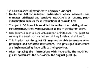
• Unlike the full virtualization architecture which intercepts and
emulates privileged and sensitive instructions at runtime, para-
virtualization handles these instructions at compile time.
• The guest OS kernel is modified to replace the privileged and
sensitive instructions with hypercalls to the hypervisor or VMM.
• Xen assumes such a para-virtualization architecture. The guest OS
running in a guest domain may run at Ring 1 instead of at Ring 0.
• This implies that the guest OS may not be able to execute some
privileged and sensitive instructions. The privileged instructions
are implemented by hypercalls to the hypervisor.
• After replacing the instructions with hypercalls, the modified
guest OS emulates the behavior of the original guest OS.
43.
Example 3.3 VMwareESX Server for Para-Virtualization
43
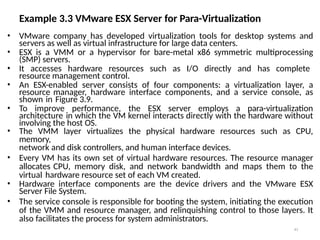
• VMware company has developed virtualization tools for desktop systems and
servers as well as virtual infrastructure for large data centers.
• ESX is a VMM or a hypervisor for bare-metal x86 symmetric multiprocessing
(SMP) servers.
• It accesses hardware resources such as I/O directly and has complete
resource management control.
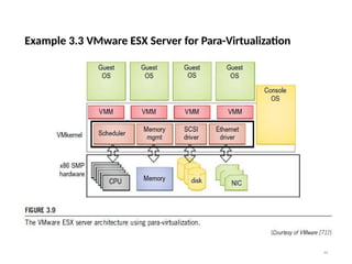
• An ESX-enabled server consists of four components: a virtualization layer, a
resource manager, hardware interface components, and a service console, as
shown in Figure 3.9.
• To improve performance, the ESX server employs a para-virtualization
architecture in which the VM kernel interacts directly with the hardware without
involving the host OS.
• The VMM layer virtualizes the physical hardware resources such as CPU,
memory,
network and disk controllers, and human interface devices.
• Every VM has its own set of virtual hardware resources. The resource manager
allocates CPU, memory disk, and network bandwidth and maps them to the
virtual hardware resource set of each VM created.
• Hardware interface components are the device drivers and the VMware ESX
Server File System.
• The service console is responsible for booting the system, initiating the execution
of the VMM and resource manager, and relinquishing control to those layers. It
also facilitates the process for system administrators.
3.3 VIRTUALIZATION OFCPU, MEMORY, AND I/O DEVICES
45
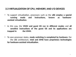
• To support virtualization, processors such as the x86 employ a special
running mode and instructions, known as hardware-
assisted virtualization.
• In this way, the VMM and guest OS run in different modes and all
sensitive instructions of the guest OS and its applications are
trapped in the VMM.
• To save processor states, mode switching is completed by hardware. For
the x86 architecture, Intel and AMD have proprietary technologies
for hardware-assisted virtualization.
46.
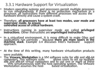
3.3.1 Hardware Supportfor Virtualization
46
• Modern operating systems and processors permit multiple processes
to run simultaneously. If there is no protection mechanism in a
processor, all instructions from different processes will access the
hardware directly and cause a system crash.
• Therefore, all processors have at least two modes, user mode and
supervisor mode, to ensure
controlled access of critical hardware.
• Instructions running in supervisor mode are called privileged
instructions. Other instructions are unprivileged instructions.
• In a virtualized environment, it is more difficult to make OSes and
applications run correctly because there are more layers in the
machine stack. Example 3.4 discusses Intel’s hardware support
approach.
• At the time of this writing, many hardware virtualization products
were available.
• The Vmware Workstation is a VM software suite for x86 and x86-64
computers. This software suite allows users to set up multiple
x86 and x86-64 virtual computers and to use one or more of these
VMs simultaneously with the host operating system. The VMware
Workstation assumes the host- based virtualization.
47.
• Xen isa hypervisor for use in IA-32, x86-64, Itanium, and PowerPC
970 hosts. Actually, Xen modifies Linux as the lowest and most
privileged layer, or a hypervisor. One or more guest OS can run on top
of the hypervisor.
• KVM (Kernel-based Virtual Machine) is a Linux kernel
virtualization infrastructure. KVM can support hardware-assisted
virtualization and para-virtualization by using the Intel VT-x or AMD-
v and VirtIO framework, respectively.
• The VirtIO framework includes a para-virtual Ethernet card, a disk
I/O controller, a balloon device for adjusting guest memory usage,
and a VGA graphics interface using VMware drivers.
48.
3.3.2 CPU Virtualization
48
•A VM is a duplicate of an existing computer system in which a majority of
the VM instructions are executed on the host processor in native
mode.
• Thus, unprivileged instructions of VMs run directly on the host machine
for higher efficiency. Other critical instructions should be
handled carefully for correctness and stability.
• The critical instructions are divided into three categories:
1) privileged instructions, 2) control-sensitive instructions, and 3)
behavior-sensitive instructions.
• Privileged instructions execute in a privileged mode and will be trapped if
executed outside this mode.
• Control-sensitive instructions attempt to change the configuration of
resources used.
• Behavior-sensitive instructions have different behaviors depending on the
configuration of resources, including the load and store operations
over the virtual memory.
49.
3.3.2 CPU Virtualization
49
•A CPU architecture is virtualizable if it supports the ability to run the
VM’s privileged and unprivileged instructions in the CPU’s user
mode while the VMM runs in supervisor mode.
• When the privileged instructions including control- and behavior-
sensitive instructions of a VM are executed, they are trapped in
the VMM. In this case, the VMM acts as a unified mediator for
hardware access from different VMs to guarantee the
correctness and stability of the whole system.
• However, not all CPU architectures are virtualizable. RISC CPU
architectures can be naturally virtualized because all control-
and behavior-sensitive instructions are privileged instructions.
• On the contrary, x86 CPU architectures are not primarily designed to
support virtualization. This is because about 10 sensitive
instructions, such as SGDT (Store Global Descriptor Table Register)
and SMSW (Store Machine Status Word), are not privileged
instructions. When these instructions execute in
virtualization, they cannot be trapped in the VMM.
50.
3.3.2 CPU Virtualization
50
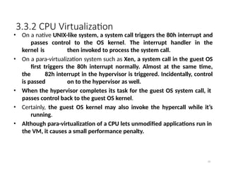
•On a native UNIX-like system, a system call triggers the 80h interrupt and
passes control to the OS kernel. The interrupt handler in the
kernel is then invoked to process the system call.
• On a para-virtualization system such as Xen, a system call in the guest OS
first triggers the 80h interrupt normally. Almost at the same time,
the 82h interrupt in the hypervisor is triggered. Incidentally, control
is passed on to the hypervisor as well.
• When the hypervisor completes its task for the guest OS system call, it
passes control back to the guest OS kernel.
• Certainly, the guest OS kernel may also invoke the hypercall while it’s
running.
• Although para-virtualization of a CPU lets unmodified applications run in
the VM, it causes a small performance penalty.
51.
3.3.2.1 Hardware-Assisted CPUVirtualization
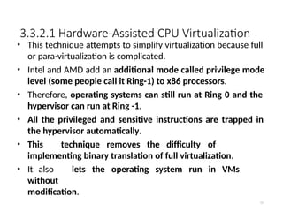
51
• This technique attempts to simplify virtualization because full
or para-virtualization is complicated.
• Intel and AMD add an additional mode called privilege mode
level (some people call it Ring-1) to x86 processors.
• Therefore, operating systems can still run at Ring 0 and the
hypervisor can run at Ring -1.
• All the privileged and sensitive instructions are trapped in
the hypervisor automatically.
• This technique removes the difficulty of
implementing binary translation of full virtualization.
• It also lets the operating system run in VMs
without
modification.
52.
3.3.3 Memory Virtualization
52
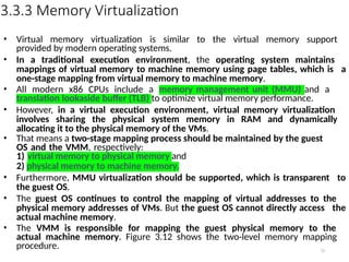
•Virtual memory virtualization is similar to the virtual memory support
provided by modern operating systems.
• In a traditional execution environment, the operating system maintains
mappings of virtual memory to machine memory using page tables, which is a
one-stage mapping from virtual memory to machine memory.
• All modern x86 CPUs include a memory management unit (MMU) and a
translation lookaside buffer (TLB) to optimize virtual memory performance.
• However, in a virtual execution environment, virtual memory virtualization
involves sharing the physical system memory in RAM and dynamically
allocating it to the physical memory of the VMs.
• That means a two-stage mapping process should be maintained by the guest
OS and the VMM, respectively:
1) virtual memory to physical memory and
2) physical memory to machine memory.
• Furthermore, MMU virtualization should be supported, which is transparent to
the guest OS.
• The guest OS continues to control the mapping of virtual addresses to the
physical memory addresses of VMs. But the guest OS cannot directly access the
actual machine memory.
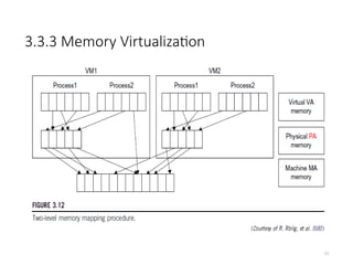
• The VMM is responsible for mapping the guest physical memory to the
actual machine memory. Figure 3.12 shows the two-level memory mapping
procedure.
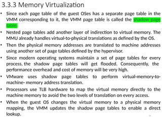
3.3.3 Memory Virtualization
•Since each page table of the guest OSes has a separate page table in the
VMM corresponding to it, the VMM page table is called the shadow page
table.
• Nested page tables add another layer of indirection to virtual memory. The
MMU already handles virtual-to-physical translations as defined by the OS.
• Then the physical memory addresses are translated to machine addresses
using another set of page tables defined by the hypervisor.
• Since modern operating systems maintain a set of page tables for every
process, the shadow page tables will get flooded. Consequently, the
performance overhead and cost of memory will be very high.
• VMware uses shadow page tables to perform virtual-memory-to-
machine- memory address translation.
• Processors use TLB hardware to map the virtual memory directly to the
machine memory to avoid the two levels of translation on every access.
• When the guest OS changes the virtual memory to a physical memory
mapping, the VMM updates the shadow page tables to enable a direct
lookup. 54
55.
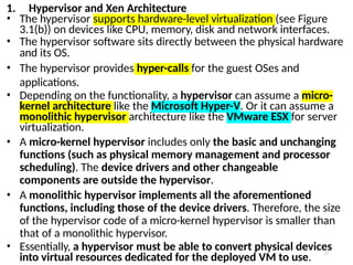
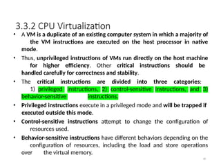
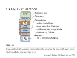
3.3.4 I/O Virtualization
55
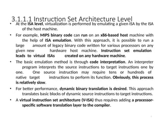
•I/O virtualization involves managing the routing of I/O requests between
virtual devices and the shared physical hardware.
• At the time of this writing, there are three ways to implement I/O
virtualization:
1) full device emulation, 2) para-virtualization, and 3) direct I/O.
• Full device emulation is the first approach for I/O virtualization.
Generally, this approach emulates well-known, real-world devices.
– All the functions of a device or bus infrastructure, such as device
enumeration, identification, interrupts, and DMA, are replicated in
software.
– This software is located in the VMM and acts as a virtual device.
The I/O access requests of the guest OS are trapped in the VMM
which interacts with the I/O devices. The full device emulation
approach is shown in Figure 3.14.
• A single hardware device can be shared by multiple VMs that run
concurrently. However, software emulation runs much slower than
the hardware it emulates [10,15].
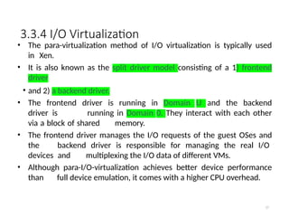
3.3.4 I/O Virtualization
•The para-virtualization method of I/O virtualization is typically used
in Xen.
• It is also known as the split driver model consisting of a 1) frontend
driver
• and 2) a backend driver.
• The frontend driver is running in Domain U and the backend
driver is running in Domain 0. They interact with each other
via a block of shared memory.
• The frontend driver manages the I/O requests of the guest OSes and
the backend driver is responsible for managing the real I/O
devices and multiplexing the I/O data of different VMs.
• Although para-I/O-virtualization achieves better device performance
than full device emulation, it comes with a higher CPU overhead.
57
58.
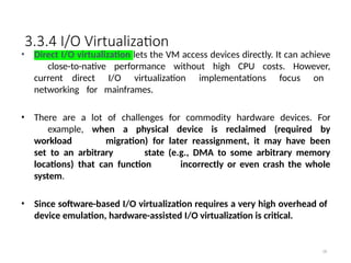
3.3.4 I/O Virtualization
58
•Direct I/O virtualization lets the VM access devices directly. It can achieve
close-to-native performance without high CPU costs. However,
current direct I/O virtualization implementations focus on
networking for mainframes.
• There are a lot of challenges for commodity hardware devices. For
example, when a physical device is reclaimed (required by
workload migration) for later reassignment, it may have been
set to an arbitrary state (e.g., DMA to some arbitrary memory
locations) that can function incorrectly or even crash the whole
system.
• Since software-based I/O virtualization requires a very high overhead of
device emulation, hardware-assisted I/O virtualization is critical.
59.
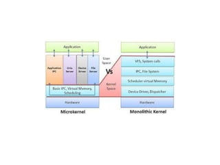
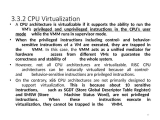
3.3.4 I/O Virtualization
59
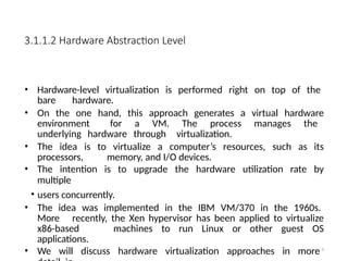
•Another way to help I/O virtualization is via self-virtualized I/O (SV-IO)
[47].
• The key idea of SV-IO is to harness the rich resources of a multicore
processor. All tasks associated with virtualizing an I/O device
are encapsulated in SV-IO.
• It provides virtual devices and an associated access API to VMs and a
management API to the VMM.
• SV-IO defines one virtual interface (VIF) for every kind of virtualized I/O
device, such as virtual network interfaces, virtual block devices
(disk), virtual camera devices, and others.
• The guest OS interacts with the VIFs via VIF device drivers. Each VIF
consists of two message queues. One is for outgoing messages to
the devices and the other is for incoming messages from the
devices. In addition, each VIF has a unique ID for identifying it in
SV-IO.
60.
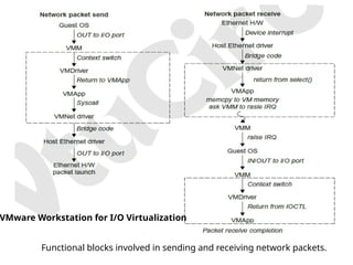
Functional blocks involvedin sending and receiving network packets.
VMware Workstation for I/O Virtualization
61.
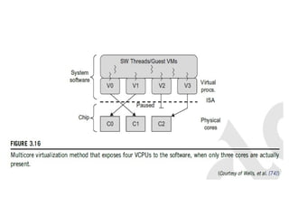
3.3.5 Virtualization inMulti-Core Processor
61
• Virtualizing a multi-core processor is relatively more complicated
than virtualizing a uni-core processor.
• There are mainly two difficulties:
• Application programs must be parallelized to use all cores fully, and
software must explicitly assign tasks to the cores, which is a very
complex problem.
• New programming models, languages, and libraries are needed to
make parallel programming easier.
• The second challenge has spawned research involving scheduling
algorithms and resource management policies.
• Wells, et al. [74] proposed a multicore virtualization method to
allow hardware designers to get an abstraction of the low-level
details of the processor cores.
• This technique alleviates the burden and inefficiency of
managing hardware resources by software.
• It is located under the ISA and remains unmodified by the operating
system or VMM (hypervisor).
63.
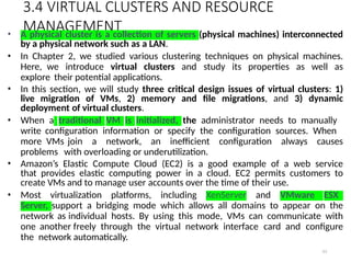
3.4 VIRTUAL CLUSTERSAND RESOURCE
MANAGEMENT
63
• A physical cluster is a collection of servers (physical machines) interconnected
by a physical network such as a LAN.
• In Chapter 2, we studied various clustering techniques on physical machines.
Here, we introduce virtual clusters and study its properties as well as
explore their potential applications.
• In this section, we will study three critical design issues of virtual clusters: 1)
live migration of VMs, 2) memory and file migrations, and 3) dynamic
deployment of virtual clusters.
• When a traditional VM is initialized, the administrator needs to manually
write configuration information or specify the configuration sources. When
more VMs join a network, an inefficient configuration always causes
problems with overloading or underutilization.
• Amazon’s Elastic Compute Cloud (EC2) is a good example of a web service
that provides elastic computing power in a cloud. EC2 permits customers to
create VMs and to manage user accounts over the time of their use.
• Most virtualization platforms, including XenServer and VMware ESX
Server, support a bridging mode which allows all domains to appear on the
network as individual hosts. By using this mode, VMs can communicate with
one another freely through the virtual network interface card and configure
the network automatically.
64.
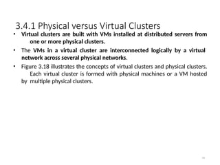
3.4.1 Physical versusVirtual Clusters
64
• Virtual clusters are built with VMs installed at distributed servers from
one or more physical clusters.
• The VMs in a virtual cluster are interconnected logically by a virtual
network across several physical networks.
• Figure 3.18 illustrates the concepts of virtual clusters and physical clusters.
Each virtual cluster is formed with physical machines or a VM hosted
by multiple physical clusters.
3.4.1 Physical versusVirtual Clusters
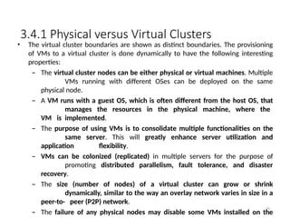
66
• The virtual cluster boundaries are shown as distinct boundaries. The provisioning
of VMs to a virtual cluster is done dynamically to have the following interesting
properties:
– The virtual cluster nodes can be either physical or virtual machines. Multiple
VMs running with different OSes can be deployed on the same
physical node.
– A VM runs with a guest OS, which is often different from the host OS, that
manages the resources in the physical machine, where the
VM is implemented.
– The purpose of using VMs is to consolidate multiple functionalities on the
same server. This will greatly enhance server utilization and
application flexibility.
– VMs can be colonized (replicated) in multiple servers for the purpose of
promoting distributed parallelism, fault tolerance, and disaster
recovery.
– The size (number of nodes) of a virtual cluster can grow or shrink
dynamically, similar to the way an overlay network varies in size in a
peer-to- peer (P2P) network.
– The failure of any physical nodes may disable some VMs installed on the
67.
3.4.1 Physical versusVirtual Clusters
• Since system virtualization has been widely used, it is necessary to
effectively manage VMs running on a mass of physical computing nodes (also
called virtual clusters) and consequently build a high-performance
virtualized computing environment.
• This involves virtual cluster deployment, monitoring and management over
large- scale clusters, as well as resource scheduling, load balancing,
server consolidation, fault tolerance, and other techniques.
• The different node colors in Figure 3.18 refer to different virtual clusters. In
a virtual cluster system, it is quite important to store the large number of VM
images efficiently.
67
68.
3.4.1 Physical versusVirtual Clusters
68
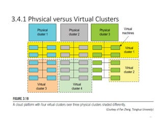
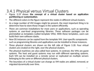
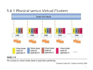
• Figure 3.19 shows the concept of a virtual cluster based on application
partitioning or customization.
• The different colors in the figure represent the nodes in different virtual clusters.
• As a large number of VM images might be present, the most important thing is to
determine how to store those images in the system efficiently.
• There are common installations for most users or applications, such as operating
systems or user-level programming libraries. These software packages can be
preinstalled as templates (called template VMs). With these templates, users can
build their own software stacks.
• New OS instances can be copied from the template VM. User-specific components
such as programming libraries and applications can be installed to those instances.
• Three physical clusters are shown on the left side of Figure 3.18. Four virtual
clusters are created on the right, over the physical clusters.
• The physical machines are also called host systems. In contrast, the VMs are guest
systems. The host and guest systems may run with different operating systems.
Each VM can be installed on a remote server or replicated on multiple servers
belonging to the same or different physical clusters.
• The boundary of a virtual cluster can change as VM nodes are added, removed, or
migrated dynamically over time.
3.4.1.1 Fast Deploymentand Effective
Scheduling Fast Deployment
70
• The system should have the capability of fast deployment. Here, deployment
means two things:
• 1) to construct and distribute software stacks (OS, libraries, applications) to a
physical node inside clusters as fast as possible.
• 2) to quickly switch runtime environments from one user’s virtual cluster to
another user’s virtual cluster. If one user finishes using his system, the
corresponding virtual cluster should shut down or suspend quickly to save the
resources to run other VMs for other users.
71.
3.4.1.1 Fast Deploymentand Effective
Scheduling Effective Scheduling
71
• The concept of “green computing” has attracted much attention recently. However,
previous approaches have focused on saving the energy cost of components in a
single workstation without a global vision. Consequently, they do not necessarily
reduce the power consumption of the whole cluster.
• The live migration of VMs allows workloads of one node to transfer to another node.
However, it does not guarantee that VMs can randomly migrate among themselves. In
fact, the potential overhead caused by live migrations of VMs cannot be ignored.
• The overhead may have serious negative effects on cluster utilization, throughput,
and QoS issues.
• Therefore, the challenge is to determine how to design migration strategies to
implement green computing without influencing the performance of clusters.
• Another advantage of virtualization is load balancing of applications in a virtual cluster.
Load balancing can be achieved using the load index and frequency of user logins.
• The automatic scale-up and scale-down mechanism of a virtual cluster can be
implemented based on this model. Consequently, we can increase the resource
utilization of nodes and shorten the response time of systems.
• Mapping VMs onto the most appropriate physical node should promote performance.
Dynamically adjusting loads among nodes by live migration of VMs is desired, when the
loads on cluster nodes become quite unbalanced.
72.
3.4.1.2 High-Performance VirtualStorage
72
• A template is a disk image that includes a preinstalled operating system with or
without certain application software.
• The template VM can be distributed to several physical hosts in the cluster to
customize the VMs.
• In addition, existing software packages reduce the time for customization.
• It is important to efficiently manage the disk spaces occupied by template
software packages. Some storage architecture design can be applied to reduce duplicated
blocks in a distributed file system of virtual clusters. Hash values are used to compare
the contents of data blocks.
• Basically, there are four steps to deploy a group of VMs onto a target cluster: 1)
preparing the disk image, 2) configuring the VMs, 3) choosing the destination nodes,
and 4) executing the VM deployment command on every host.
• Users choose a proper template according to their requirements and make a duplicate
of it as their own disk image.
• Templates could implement the COW (Copy on Write) format. A new COW backup
file is very small and easy to create and transfer. Therefore, it definitely reduces disk
space consumption.
• In addition, VM deployment time is much shorter than that of copying the whole raw
image file.
73.
3.4.1.2 High-Performance VirtualStorage
• Every VM is configured with a name, disk image, network setting, and
allocated CPU and memory.
• One needs to record each VM configuration into a file. However, this method
is
• inefficient when managing a large group of VMs.
• VMs with the same configurations could use pre-edited profiles to simplify
the process. In this scenario, the system configures the VMs according to the
chosen profile.
• A strategy to choose the proper destination host for any VM is needed.
The deployment principle is to fulfill the VM requirement and to balance
workloads among the whole host network.
73
74.
3.4.2 Live VMMigration Steps and
Performance Effects
74
• When a VM fails, its role could be replaced by another VM on a different
node.
• This is different from physical-to-physical failover in a traditional physical
cluster. The advantage is enhanced failover flexibility.
• The potential drawback is that a VM must stop playing its role if its
residing host node fails. However, this problem can be mitigated with
VM life migration.
75.
3.4.2 Live VMMigration Steps and Performance
Effects
75
• There are four ways to manage a virtual cluster.
• First, you can use a guest-based manager, by which the cluster manager
resides on a guest system. In this case, multiple VMs form a virtual cluster.
• For example, openMosix is an open source Linux cluster running different guest
systems on top of the Xen hypervisor.
• Another example is Sun’s cluster Oasis, an experimental Solaris cluster
of VMs supported by a VMware VMM.
• Second, you can build a cluster manager on the host systems. The host-based
manager supervises the guest systems and can restart the guest system on
another physical machine.
• A good example is the VMware HA system that can restart a guest system after
failure.
• These two cluster management systems are either guest-only or host-only, but
they do not mix.
• A third way to manage a virtual cluster is to use an independent cluster
manager on both the host and guest systems. This will make infrastructure
management more complex.
• Finally, you can use an integrated cluster on the guest and host systems. This
means the manager must be designed to distinguish between virtualized
resources and physical resources.
76.
3.4.2 Live VMMigration Steps and
Performance Effects
• Various cluster management schemes can be greatly enhanced
when VM life migration is enabled with minimal overhead.
• VMs can be live-migrated from one physical machine to another; in
case of
• failure, one VM can be replaced by another VM.
• The major attraction of this scenario is that virtual clustering
provides dynamic resources that can be quickly put together
upon user demand or after a node failure.
• When a VM runs a live service, it is necessary to make a trade-
off to ensure that the migration occurs in a manner that
minimizes all three metrics. The motivation is to design a live
VM migration scheme with negligible downtime, the lowest
network bandwidth consumption, and a reasonable total migration
time.
76
77.
3.4.2 Live VMMigration Steps and
Performance Effects
• A VM can be in one of the following four states:
• An inactive state is defined by the virtualization platform, under
which the VM is not enabled.
• An active state refers to a VM that has been instantiated at the
virtualization platform to perform a real task.
• A paused state corresponds to a VM that has been instantiated but disabled
to process a task or paused in a waiting state.
• A VM enters the suspended state if its machine file and virtual resources
are
• stored back to the disk.
77
78.
3.4.2 Live VMMigration Steps and Performance
Effects
78
79.
3.4.2 Live VMMigration Steps and
Performance Effects
79
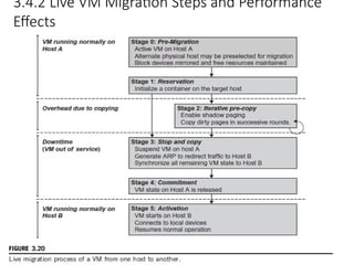
As shown in Figure 3.20, live migration of a VM consists of the following six
steps:
• Steps 0 and 1: Start migration. This step makes preparations for the
migration, including determining the migrating VM and the
destination host. Although users could manually make a VM
migrate to an appointed host, in most circumstances, the migration is
automatically started by strategies such as load balancing and server
consolidation.
• Steps 2: Transfer memory. Since the whole execution state of the VM is
stored in memory, sending the VM’s memory to the destination
node ensures continuity of the service provided by the VM. All of the
memory data is transferred in the first round, and then the
migration controller recopies the memory data which is changed in
the last round. These steps keep iterating until the dirty portion
of the memory is small enough to handle the final copy.
Although precopying memory is performed iteratively, the
execution of programs is not obviously interrupted.
80.
3.4.2 Live VMMigration Steps and
Performance Effects
80
• Step 3: Suspend the VM and copy the last portion of the data. The
migrating VM’s execution is suspended when the last round’s
memory data is transferred. Other nonmemory data such as
CPU and network states should be sent as well. During this step,
the VM is stopped and its applications will no longer run. This
“service unavailable” time is called the “downtime” of migration,
which should be as short as possible so that it can be negligible to
users.
• Steps 4 and 5: Commit and activate the new host. After all the needed
data is copied, on the destination host, the VM reloads the states
and recovers the execution of programs in it, and the service
provided by this VM continues. Then the network connection is
redirected to the new VM and the dependency to the source
host is cleared. The whole migration process finishes by removing
the original VM from the source host.
81.
3.4.2 Live VMMigration Steps and
Performance Effects
81
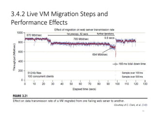
• Figure 3.21 shows the effect on the data transmission rate (Mbit/second)
of live migration of a VM from one host to another. Before copying the
VM with 512 KB files for 100 clients, the data throughput was 870
MB/second.
• The first precopy takes 63 seconds, during which the rate is reduced to
765 MB/second. Then the data rate reduces to 694 MB/second in
9.8 seconds for more iterations of the copying process.
• The system experiences only 165 ms of downtime, before the VM is
restored at the destination host. This experimental result shows a
very small migration overhead in live transfer of a VM between
host nodes. This is critical to achieve dynamic cluster
reconfiguration and disaster recovery as needed in cloud
computing.
82.
3.4.2 Live VMMigration Steps and
Performance Effects
82
83.
3.4.2 Live VMMigration Steps and
Performance Effects Alternative Approaches
83
• In the pre-copy phase, although a VM service is still available, much
performance degradation will occur because the migration
daemon continually consumes network bandwidth to transfer
dirty pages in each round. Moreover, the maximum number of
iterations must be set because not all applications’ dirty pages are
ensured to converge to a small writable working set over multiple
rounds. In fact, these issues with the pre-copy approach are
caused by the large amount of transferred data during the whole
migration process.
• A checkpointing/recovery and trace/replay approach (CR/ TR-Motion) is
proposed to provide fast VM migration. This approach transfers
the execution trace file in iterations rather than dirty pages, which
is logged by a trace daemon. Apparently, the total size of all log
files is much less than that of dirty pages. The total
migration time and downtime of migration are drastically
reduced. However, CR/TR-Motion is valid only when the log replay
rate is larger than the log growth rate.
84.
3.4.2 Live VMMigration Steps and
Performance Effects Alternative Approaches
84
• Another strategy of post-copy is introduced for live migration of VMs.
Here, all memory pages are transferred only once during the
whole migration process and the baseline total migration time is
reduced. But the downtime is much higher than that of pre-copy due
to the latency of fetching pages from the source node before the VM
can be resumed on the target. With the advent of multicore
or many-core machines, abundant CPU resources are available. Even if
several VMs reside on a same multicore machine, CPU resources are
still rich because physical CPUs are frequently amenable to
multiplexing.
• We can exploit these copious CPU resources to compress page frames and
the amount of transferred data can be significantly reduced.
Memory compression algorithms typically have little
memory overhead. Decompression is simple and very fast and
requires no memory for decompression.
85.
3.4.3 Migration ofMemory, Files, and Network Resources
3.4.3.1 Memory Migration:
• Memory migration is one of the most important aspects of VM migration. Moving the
memory instance of a VM from one physical host to another can be approached in any
number of ways.
• Memory migration can be in a range of hundreds of megabytes to a few gigabytes in a
typical system today, and it needs to be done in an efficient manner.
• The Internet Suspend-Resume (ISR) technique deals with situations where the
migration of live machines is not a necessity (Cold Migration).
• Predictably, the downtime (the period during which the service is unavailable due to
there being no currently executing instance of a VM) is high.
• The ISR technique exploits temporal locality as memory states are likely to have
considerable overlap in the suspended and the resumed instances of a VM.
• Temporal locality refers to the fact that the memory states differ only by the amount of
work done since a VM was last suspended before being initiated for migration.
• To exploit temporal locality, each file in the file system is represented as a tree of small
sub-files. A copy of this tree exists in both the suspended and resumed VM instances.
• The advantage of using a tree-based representation of files is that the caching ensures
the transmission of only those files which have been changed.
• . 78
86.
3.4.3 Migration ofMemory, Files, and Network Resources
86
3.4.3.2 File System Migration
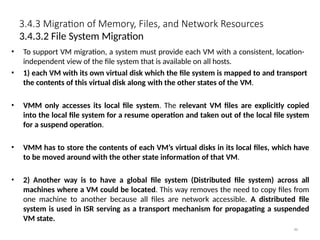
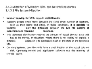
• To support VM migration, a system must provide each VM with a consistent, location-
independent view of the file system that is available on all hosts.
• 1) each VM with its own virtual disk which the file system is mapped to and transport
the contents of this virtual disk along with the other states of the VM.
• VMM only accesses its local file system. The relevant VM files are explicitly copied
into the local file system for a resume operation and taken out of the local file system
for a suspend operation.
• VMM has to store the contents of each VM’s virtual disks in its local files, which have
to be moved around with the other state information of that VM.
• 2) Another way is to have a global file system (Distributed file system) across all
machines where a VM could be located. This way removes the need to copy files from
one machine to another because all files are network accessible. A distributed file
system is used in ISR serving as a transport mechanism for propagating a suspended
VM state.
87.
3.4.3 Migration ofMemory, Files, and Network Resources
87
3.4.3.2 File System Migration
• In smart copying, the VMM exploits spatial locality.
• Typically, people often move between the same small number of locations,
such as their home and office. In these conditions, it is possible to
transmit only the difference between the two file systems at
suspending and resuming locations.
• This technique significantly reduces the amount of actual physical data that
has to be moved. In situations where there is no locality to exploit, a
different approach is to synthesize much of the state at the resuming
site.
• On many systems, user files only form a small fraction of the actual data on
disk. Operating system and application software use the majority of
storage space.
88.
3.4.3 Migration ofMemory, Files, and Network Resources
3.4.3.3 Network Migration
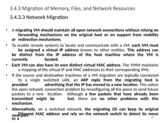
• A migrating VM should maintain all open network connections without relying on
forwarding mechanisms on the original host or on support from mobility
or redirection mechanisms.
• To enable remote systems to locate and communicate with a VM, each VM must
be assigned a virtual IP address known to other entities. This address can
be distinct from the IP address of the host machine where the VM is
currently located.
• Each VM can also have its own distinct virtual MAC address. The VMM maintains
a mapping of the virtual IP and MAC addresses to their corresponding VMs.
• If the source and destination machines of a VM migration are typically connected
to a single switched LAN, an ARP reply from the migrating host is
provided advertising that the IP has moved to a new location. This solves
the open network connection problem by reconfiguring all the peers to send future
packets to a new location. Although a few packets that have already been
transmitted might be lost, there are no other problems with this
mechanism.
• Alternatively, on a switched network, the migrating OS can keep its original
Ethernet MAC address and rely on the network switch to detect its move
to a
new port. 81
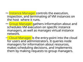
•• Instance Managercontrols the execution,
inspection, and terminating of VM instances on
the host where it runs.
•• Group Manager gathers information about and
schedules VM execution on specific instance
managers, as well as manages virtual instance
network.
•• Cloud Manager is the entry-point into the cloud
for users and administrators. It queries node
managers for information about resources,
makes scheduling decisions, and implements
them by making requests to group managers.
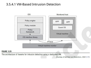
3.5.4.1 VM-Based IntrusionDetection
• Intrusions are unauthorized access to a certain computer from local or network
users and intrusion detection is used to recognize the unauthorized access.
• An intrusion detection system (IDS) is built on operating systems, and is based
on the characteristics of intrusion actions.
• A typical IDS can be classified as a host-based IDS (HIDS) or a network-based
IDS (NIDS), depending on the data source.
• A HIDS can be implemented on the monitored system. When the monitored
system is attacked by hackers, the HIDS also faces the risk of being attacked.
• A NIDS is based on the flow of network traffic which can’t detect fake actions.
• Virtualization-based intrusion detection can isolate guest VMs on the same
hardware platform.
• Even some VMs can be invaded successfully; they never influence other VMs,
which is similar to the way in which a NIDS operates.
• Furthermore, a VMM monitors and audits access requests for hardware and
system software. This can avoid fake actions and possess the merit of a HIDS.
• There are two different methods for implementing a VM-based IDS: Either the
IDS is an independent process in each VM or a high-privileged VM on the VMM;
or the IDS is integrated into the VMM has the same privilege to access the hardware as
well as the VMM.
95.
• The VM-basedIDS contains a policy engine and a policy
module.
• The policy framework can monitor events in different
guest VMs by operating system interface library and
PTrace indicates trace to secure policy of monitored
host.
• It’s difficult to predict and prevent all intrusions without
delay.
• Therefore, an analysis of the intrusion action is
extremely important after an intrusion occurs.
• At the time of this writing, most computer systems use
logs to analyze attack actions, but it is hard to ensure
the credibility and integrity of a log.
• The IDS log service is based on the operating system
kernel. Thus, when an operating system is invaded by
attackers, the log service should be unaffected.
![3.1.1 Levels of Virtualization Implementation
4
• A traditional computer runs with a host operating system specially tailored for its
hardware architecture, as shown in Figure 3.1(a).
• After virtualization, different user applications managed by their own operating
systems (guest OS) can run on the same hardware, independent of the host OS.
• This is often done by adding additional software, called a virtualization layer as
shown in Figure 3.1(b).
• This virtualization layer is known as hypervisor or virtual machine monitor (VMM)
[54]. The VMs are shown in the upper boxes, where applications run with their
own guest OS over the virtualized CPU, memory, and I/O resources.
• The main function of the software layer for virtualization is to virtualize the
physical hardware of a host machine into virtual resources to be used by the VMs,
exclusively.
• This can be implemented at various operational levels, as we will discuss shortly.](https://image.slidesharecdn.com/module02-cloudcomputing-250829084835-e8c97e38/85/MODULE-02-CLOUD-COMPUTING-Virtual-Machines-and-Virtualization-of-Clusters-and-Data-Centers-pptx-4-320.jpg)
![29
1. The Xen Architecture
• Xen is an open source hypervisor program developed by
Cambridge University.
• Xen is a microkernel hypervisor, which separates the policy from the
mechanism.
• The Xen hypervisor implements all the mechanisms, leaving the policy to
be handled by Domain 0, as shown in Figure 3.5.
• Xen does not include any device drivers natively [7]. It just provides a
mechanism by which a guest OS can have direct access to the
physical devices. As a result, the size of the Xen hypervisor is kept rather
small.
• Xen provides a virtual environment located between the hardware and
the OS.
• A number of vendors are in the process of developing commercial Xen
hypervisors, among them are Citrix XenServer [62] and Oracle VM [42].
• The core components of a Xen system are the hypervisor, kernel, and
applications. The organization of the three components is important.](https://image.slidesharecdn.com/module02-cloudcomputing-250829084835-e8c97e38/85/MODULE-02-CLOUD-COMPUTING-Virtual-Machines-and-Virtualization-of-Clusters-and-Data-Centers-pptx-29-320.jpg)
![3.3.4 I/O Virtualization
55
• I/O virtualization involves managing the routing of I/O requests between
virtual devices and the shared physical hardware.
• At the time of this writing, there are three ways to implement I/O
virtualization:
1) full device emulation, 2) para-virtualization, and 3) direct I/O.
• Full device emulation is the first approach for I/O virtualization.
Generally, this approach emulates well-known, real-world devices.
– All the functions of a device or bus infrastructure, such as device
enumeration, identification, interrupts, and DMA, are replicated in
software.
– This software is located in the VMM and acts as a virtual device.
The I/O access requests of the guest OS are trapped in the VMM
which interacts with the I/O devices. The full device emulation
approach is shown in Figure 3.14.
• A single hardware device can be shared by multiple VMs that run
concurrently. However, software emulation runs much slower than
the hardware it emulates [10,15].](https://image.slidesharecdn.com/module02-cloudcomputing-250829084835-e8c97e38/85/MODULE-02-CLOUD-COMPUTING-Virtual-Machines-and-Virtualization-of-Clusters-and-Data-Centers-pptx-55-320.jpg)
![3.3.4 I/O Virtualization
59
• Another way to help I/O virtualization is via self-virtualized I/O (SV-IO)
[47].
• The key idea of SV-IO is to harness the rich resources of a multicore
processor. All tasks associated with virtualizing an I/O device
are encapsulated in SV-IO.
• It provides virtual devices and an associated access API to VMs and a
management API to the VMM.
• SV-IO defines one virtual interface (VIF) for every kind of virtualized I/O
device, such as virtual network interfaces, virtual block devices
(disk), virtual camera devices, and others.
• The guest OS interacts with the VIFs via VIF device drivers. Each VIF
consists of two message queues. One is for outgoing messages to
the devices and the other is for incoming messages from the
devices. In addition, each VIF has a unique ID for identifying it in
SV-IO.](https://image.slidesharecdn.com/module02-cloudcomputing-250829084835-e8c97e38/85/MODULE-02-CLOUD-COMPUTING-Virtual-Machines-and-Virtualization-of-Clusters-and-Data-Centers-pptx-59-320.jpg)
![3.3.5 Virtualization in Multi-Core Processor
61
• Virtualizing a multi-core processor is relatively more complicated
than virtualizing a uni-core processor.
• There are mainly two difficulties:
• Application programs must be parallelized to use all cores fully, and
software must explicitly assign tasks to the cores, which is a very
complex problem.
• New programming models, languages, and libraries are needed to
make parallel programming easier.
• The second challenge has spawned research involving scheduling
algorithms and resource management policies.
• Wells, et al. [74] proposed a multicore virtualization method to
allow hardware designers to get an abstraction of the low-level
details of the processor cores.
• This technique alleviates the burden and inefficiency of
managing hardware resources by software.
• It is located under the ISA and remains unmodified by the operating
system or VMM (hypervisor).](https://image.slidesharecdn.com/module02-cloudcomputing-250829084835-e8c97e38/85/MODULE-02-CLOUD-COMPUTING-Virtual-Machines-and-Virtualization-of-Clusters-and-Data-Centers-pptx-61-320.jpg)