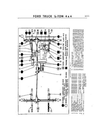
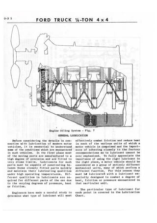
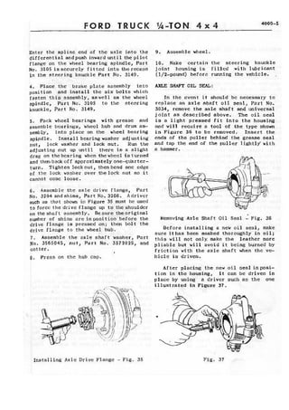
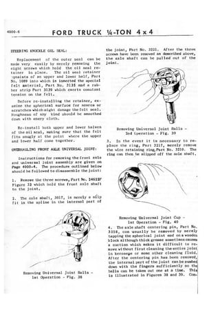
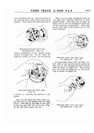
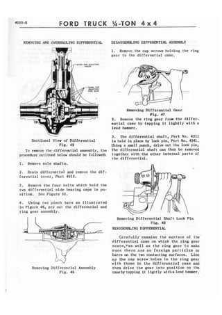
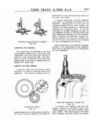
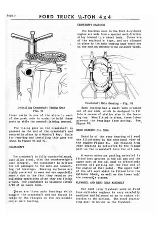
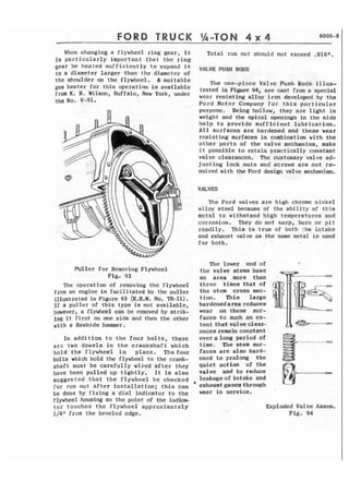
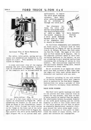
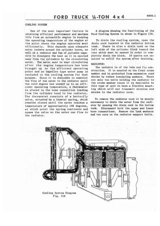
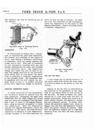
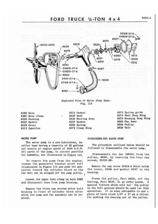
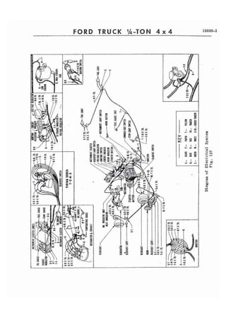
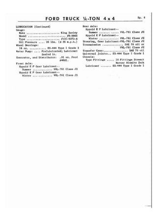
7 
- - 
MOOU GP U S OOVERNMENT & TON, 4 WHEEL DRIVE, 80' WHEELBASE RECONNAISSANCE CAR 
Identification Plate and Caution Plate Located on Instrumart Panel
0-3 2 FORD TRUCK WTON 4 x 4 
hginc Oiling System - Fig. 7 
LUBRICATIW 
Batore considering the details in con-nection 
with lubrication of modern motor 
vehiclea, i t is ~saential to underatand 
h#we of the canditiaw which are enowrntered 
in such vthiclea, In the first place moet 
of the moving parta are manufactured to a 
high degree of prcciaian and are fitted to 
very cloae limits. Lubricants for audr 
parta must be capable of penetrating be-tween 
these closely fitted parts quickly 
and maintain their lubricating qualities 
under high operating teaperaturea. D i f - 
rerent qualities in lubricants are re-quired 
Tor different parta of the car due 
t o the mrying degree8 of pressure, he8t 
qr friction. 
Engineers have made a careful study to 
qetermlne what type of lubricant will mst 
effectively cdmt frictian and reduce heat 
i n each of the various unit8 of which a 
motor vehicle is -riaad and the impart-ance 
of adhering closely to the factory 
recommendations as to lubricant cannot be 
over emphasized. To f u l l y appreciate the 
importance bf using the sight lubricant in 
the right place, a ~lotor.vJliclca hould be 
camidercd aa a group of .=tirely differaat 
mechanical units, many qf Mich perform a 
differcnt'function. For t h i s reaaon they 
must b l lubricateb with a lubricant sa-pecially 
deeigned t o combat a degree of 
heat, friction or pr,eaaure encountered in 
that oarticular d t . 
The particular t y p e o f lubricant for 
each point is covered in the Lubrication 
Chart.
TRUCK 
As illustrated in Figure 7, the engine 
is lubricated by pressure feed to the main 
connecting rod and camshaft bearings and 
by splash t o other p a r t s . The gear-type 
Oil Pump Housing is cast i n t ~ g r a lw ith the 
f r o n t Main Bearing cap and is driven from 
the crankshaft gear of the timing gear set. 
The oil pressure re1 ief and segulat ing valve 
illustrated in Figvre 8 lifts at 30 pound 
pressure which will show a gauge pressure 
f ran 15 to 30 pounris on the inst mat panel 
depading on the temperatures of the oil and 
speed of t h e engine. The oil in. the agine 
when shipped from the factory is sat isfactory 
for the f i r s t 300 miles. Arter this period 
of operation, t h e engine o i l should be drained 
and replaced with new oil of the correct 
viscosity as shown below: 
1 
Oil Relief Valve - F i g . 8 
PREVAILING TEMPERATURE RANGE: S.A.E. 
viscosity 
No. 
precautionary measure toward preventing 
accumulation of sludge or foreign mattes 
on the screen, it is suggested that this 
screen be cleaned i n gasoline before the 
plug is replaced. 
OTL CHANGES 
Under normal driving conditions, t h e 
engine oil should be changed every 2,000 
miles. By normal d r i v i n g conditions we 
mean within temperatures ranging from 32 
degrees Fahrenheit t o approximately 80 de-grees,~ 
m edium road speed and average dust 
conditions. In extremely cold weather when 
condensation and crankcase dilution might 
cause the formation of sludge in the crank-case, 
the oil should be changed more fre-quently. 
This procedure should also be followed 
with units which are operated infrequently 
and f o r short periods during cold wather. 
This type of operation promotes the accum-ulation 
of water in the crankcase result-ing 
from condensation and products of com-bustion 
within the engine. Such moisture 
and other contaminants are largely evaporated 
after the engine becomes thoroughly warmed 
up but under conditions such as those men-tioned 
above, they can be a source of cm-siderable 
trouble i f precautionary measures 
a r e not taken. 
Temperatures above 32 degrees 30 
Fahrenheit Sectional View of O i l Bath Air Cleaner 
Fig. 9 
Temperatures below 32 1 0 or 10-W WSTV TERl?ZTORY 
degrees Fahrenheit * Not withstanding the fact that the Ford 
engine is equipped with an Oil F i l t e r , as 
well as an Oil Bath Type Air Cleaner, the 
OIL, PAN DRAIN PWIG oil should be changed more freqV-znt lyw hen 
t h e units are operated under extremely 
It will be observed that the oil pump dusty conditions. The Oil Bath Air Cleaner 
screen is an integral part of the'oil pan should b e cleaned out as often as is neces-drain 
plua. Part 6730, Figure 82. As a sary t o keep the sump free from excessive
FORD TRUCK 
accumulations of dirt. Under the most se-vere 
conditions t h i s might be necessary 
every day although such extreme conditions 
are very infrequently encountered. The 
engine ventilator screen in the oil filler 
cap should also bc checked to see that i t 
does not become obstructed with dust. 
ADDING OIL 
Thc o i l Icvel should bc 
kept in the "safe driving 
r s n g e 1 f s s m a r k e d o n t h e oil 
l e v e l bayonet gouge shown in 
Figure 10. The five quarts 
of oil placed in the crank-case 
when the oi l is changed, 
brings tthe l e v e l slightly 
above the full mark on the 
measuring stick. It is not 
necessary to maintain the 
level at this point and oil 
should not necessarily be 
added u n t i l the level is down 
toward the lower part of the 
Nsafe driving rangen indi-cated 
on the gauge. 1 I t is advisable t o wait 
several minutes a f t e r the 
engine has been stopped be-z 
fore checking the o i l l e v e l , 
F*I 
= A considerable quantity of 
rml = oil rcmains in the circu-l 
a t ing system f o r . a sdort 
Oil Level p e r i o d after the engine is 
Gauge stopped <and the oil level 
Fig, 10 gauge w i l l not register ac-curately 
until this o i l has 
had s u f f i c i e n t time to drninnback i n t o 
the o i l pan. 
OIL FILTER 
The oil f i l t e r unit should be changed 
a f t e r 8,000 t o 10,000 miles of operation. 
The cleaner elcrnent and case are manufac-tured 
as a complete unit and the entire 
element must he changed (See Figure 11). 
To changc t h e o i l f l l t c r , disconncct 
the o i l l i n e a t both top and bottom of the 
liltcr unit. Remove the oil gauge unit 
which is screwed i n t o the top of the oil 
f i l t e r . Loosen t h e two cap screws which 
hold the filter bracket to the cylinder 
block and r h e clamp screw loca'ted between 
the f i l t e r and thc cylinder block. 
The f i l t e r unit can 
then be pulled upward 
out of the bracket. 
Install the new fitter 
unit i n t o t h e bracket 
on the engine and tighten 
the clamp screw. Then 
install the o i l gauge 
unit in the new filter 
and connect both the - r - 
O l r l l t l 
top and hot tom o i l 1 ines Sectional View of 
to the connections on Oil Filter Unit 
the filter unit. Fig. 11 
TRANSMISSION AND TRANSFER CASE 
b t h the transmission and transfer case 
should be lubricated with SAIZ 90-EF gear 
o i l if such lubricant is available. Since 
the s e l e c t i o n of lubricants is necessarily 
restricted in field operations, alternative 
lubricants which may be used in t h e trans-mission 
are SAE 70 oil or lubricants con-formlng 
to Quartermaster Corp s p e c i f i c a - 
tion W-L-761 Class No. 2, For the Trans-f 
e r Case, SAE 70 oil may be used. 
The same type of lubricant should be used 
for both m r and winter operation and the 
level should be maintained even with the 
filler plug. It is suggested that the lubri-cant 
be changed every 5000 miles or eqeh 
fall or spring, whichever should occur first. 
FRONT AXLE AND W E . 
Wypoid gears are used i n both the front 
and rear axle and it is, therefore, neces-sary 
to use a lrHypoid Extreme Pressuren 
type of lubricant. Gear lubricant con-forming 
to Quartermaster Corp spccifica-tion 
W-L-761 Class No. 2 is of this type 
and should be SAE 90 viscosity. 
Avoid mixing various brands of Hypoid 
lubricants. I f the brand is changed, it 
is e s s e n t i a l that the rear axle housings 
b e drained and flushed with l i g h t engine 
o i l before installing the new lubricant. 
7 
FRONT AXLE UNIVERSAL JOINTS 
massis Lubricant conforming to Quarter-master 
Corp specifications ES-444 Type No, 
1--Grade No. 1, should be used to lubricate 
these parts. Approximately 1/2 lb. (112 
pt.) is required in each teer ring knuckle 
joint housing. Remove the plug shown in 
Figure 6 to inject the lubricant.
FORD TRUCK 
PERMANENTLY LUBRICATED PARTS WHEELS AND TIRES 
The following parts arc packed with 
lubricant at the factory and will not re- Pressed steel, drop center rim wheels 
quire the addition of any lubricant unless which were especially designed for this 
disasscmbl y of the parts t)ecomcs necessary uni t , are used on the Ford Reconnaissance 
for some other reasons. and Command Car. The wheels are 16'1 in 
diameter, have a 4" rim, 5-1/21! bolt circle 
Front and rear propeller shaft and five bolt holes. They are fitted with 
Universal joints either 550 x 16 tires or 600 x 16 tires. 
Clutch throw-out bearing In cithcr case the correct inflation pres- Clutch pilot bearing sure is 24 pounds. 
Water pump 
Themost important factor controlling tire 
life is the air pressure in the tire. Tire 
In even' the flyvlleeli s inflation should, therefore, be checked at least once each week and every precaution f ram the a-~infeo r any reason, it will, of taken to prevent operati on of the vehicle course, be necessary to re-pack the pilot with tire pressures less than 20 pounds. bearing with a lubricant having a high Under-inflation not only decreases tire melting point, such as ES-444> 'ype J' life but also adds to the possibility of Grade 2. a rim bruise. 
STEERING GEAR 
The level of the lubricant in the steer-ing 
gear should be checked each 1000 miles 
and ifnecessary, addGear Lubricant W-L-761, 
Class No. 2. This will apply to either 
summer or winter operations. 
SHOCK ABSORBERS 
The shock absorbers should be refilled 
every 5,000 miles with Ford Shock Absorber 
Fluid. When refilling an instrument, clean 
i t thoroughly around the filler plug be-fore 
removing the plug, An extremely small 
particle of dirt inside the instrument 
might cause i t to become inoperative. 
Rim bruises are causedbythe tire hitting 
a curb or some other object with sufficient 
force to pinch the tire between the object 
struck and the rim. Several cords may be 
broken in the second or third layer of fabric 
but the tire will not show any outward signs 
of an injury. These cords will gradually 
wear on other cords until a bre'ak occurs. 
One of the most important reasons for close 
at tent ion to inflat ion pressures is the 
fact that this vehicle has four wheel drive. 
When both front and rear axles are driving, 
the rolling radius of all wheels must be 
equal in order to avoid prematute or ex-cessive 
wear in the axle differentials. 
CHASSIS FITTINGS CHANGING WHEEL AND TIRE 
The Lubrication Chart, Figure 6, clearly 
indicates the various fittings to which To change a whccl and t i re asseml~ly, the 
chassis lubr icarlt should be applied. A proceclure outlined below should be followed: 
semi-fluid lubricant intended for use in Y 
a pressure gun should be injected into these articular fittings. Every fitting should 1. ~pply the emergency brake. 
be wiped clean before the pressure gun is 
applied so as to avoid forcing particles 
of dirt or abrasive into the parts which 2. Block one of the wheels resting on the 
are to be lubricated. ground with a large stone or block of wood.
FORD TRUCK 
3. Place jack under a x l e close to the 
spring seat of the wheel which Is to be 
removed, and jack up car until wheel is a t 
lea'st 1 " clear of the ground, 
4 . Remove t h e f i v e nuts holding the wheel 
t o the hub. See Figure 12. The wheel can 
then be removed. 
REMOVING TIRE EROM WEEL 
Deflate the tube 
completely. Loosen 
both beads from bead 
seats on, rim, Force 
the outside bead from 
the bead seat i n t o 
the rim w e l l at a 
point apposite ihe 
valve. Be sure the 
,,, bead is in the rim 
well, then with two 
Fig. 11 t i r e tools placed 
approximately 4" on each side of the valve, 
l i f t the bead closest to you over the rim 
f l a n g e . (See Figure 1 3 . ) Follow around 
t h e flange with the tire tools until the 
outside bead is free from the rim. Then 
force t h e laaide bead into the rim well at 
until the entire bead is replaced. Always 
keep as much of t h e bead as possible in 
the rim well while installing the tire. 
Before inflating t h e tube, push t h e 
valve stem i n t o the casing as far as pos-s 
i b l e t o makc sure that the tube is not 
the top and pull Out the bottom the tire pinched under the t i r e beads. Do not let 
until i t as in Figure 13* go of the valve stem while doing this. , 
MOUNTING TIRE ON WIm: 
Inflate the tube until i t is f a i r l y 
rounded out and i n s e r t i t i n the tire. 
The tube must be placed in the t i r e with 
t h e valve stem a t the balance mark. Push 
t h e inaide bead of the t i r e into the rim 
well at the point next to the valve. Force 
the remaining portion of the bead over the 
outside flange of the rim. Do not attempt 
t o force t o o l a r g e a portion o v e r the 
flange a t one time. L i f t up on the tire, 
placing the outside bead i n rim well at 
t h e valve. Starting at e i t h e r side of the 
valve, force short length of the bead over 
t h e flange, continuing around t h e wheel 
I n f l a t e the tube to not more,than 2 
pounds pressure, working casing back and 
forth. Proper f i t t i n g of t h e t i r e is in-dicated 
by the molded l i n e on the s i d e of 
the t i r e being equally spaced from the rim 
at a l l points, 
SPARE TIRE: 
The spare t i r e and wheel assembly i s 
mounted on the back o f t h e body and held 
i n place by three nuts. The bottom of t h e 
t i r e r e s t s on a support p l a t e which is 
bolted to the bumper. T h i s support plate 
has slotted holes so that it can be adjust-ed 
up o r down to provide adequate support 
for eitheq 5.50 or 6.00 size t i r e s .
FORD TRUCK '&TON 4 x 4 1000-1 
BRAKE SYSTEM 
, Brake System - Fig, 14 
The system consists of a master cylinder The brake pedal, when depressed, moves 
in which hydraulic pressure is b u i l t up the piston within tho master cylinder; thus, 
by pressure on the brake pedal, 4 wheel sending the brake f l u i d from t h e master 
cylinders operating brake shoes against cylinder through the tubing and flexible 
each wheel drum when Pressure is applied, hose to each of the four wheeE cylinders. 
and the l i n e s msist ing of tubing, flexible 
hose, brackets and unions, interconnecting Brake f l u i d is plac'ed under pressure 
the master cylinder and wheel cylinders. each of wheel 
See Figure 14. the pistons t o move outward against the 
The master cylinder is fitted w i t h a brake shoes, bringing the shoes into con-piston, 
and the wheel cylinders are each tact with the See Figure 16= A s b 
f i t t e d w i t h two opposed pistons, a l l of PreSSUre on the brake pedal is increased, 
which are provided with cup packings, which greater hydraulic Pressure is buff t UP 
act as seals t o maintain pressure a d pre- within ,the wheel cylinders and cms.equently 
vent loss of brake f l u j d , greater force is exerted against the brake 
shoes. The ,system is self equal k i n g since 
a l l pressure is transmftted to the brake 
shoes by the column of f l u i d and no pres-sure 
can b e developed in any of the wheel 
cylinders or brake lines until the pres-sure 
is equally distributed at a11 points. 
# 
When the pressure on the foot pedal is 
. released, the retracting springs on t h e 
brake shoes return wheel cylinder pistons 
to their normal or nofffl position thereby. 
forcing the brake fluid back through . 
flexible hose and tubing into the mas. 
Brake Master Cylinder - Fig. 15 cylinder . 
- - 
the 
ter
FORD TRUCK %-TON 4 x 4 
THE MASTER CYLINDE3 
Thc compensating-type master cylinder 
Fig. 15 performs two functions: 
1. By means of the supply reservoir in 
the upper part of the housing, it maintafns 
a constant volume of f l u i d in the system 
at a l l times regardless of expansion, "heat-ing, 
n or contraction, "cooling." It also 
acts as a pump during the "bleeding1 operation. 
dust shield assembly or support plate, two 
brake shoes, the wheel cylinder assembly 
and brake shoe contracting spring. Figure 
18 shows all parts of the rear wheel cyl-inder 
in their relative assembling positions. 
The wheel cylinders, are of the straight 
bore construction, being 1" diameter on the 
front wheels and 7/8" on the sear wheels. 
Exploded View of Wheel Cylinder-- Fig. 18 
TO REMOVE THE WHEEL CYLINDER 
Should i t become necessary to remove 
t h e wheel cylinder for inspection, t h e 
following. operation should be performed: 
Disconnect the cylinder from the system 
by removing the inlet fitting and the bolts 
which hold t h e cylinder to the brake plate. 
Tt~e shoe travel is sufficient to permit the 
cylinder to be withdrawn without removing 
the brakc shoes, after the retracting spring 
has been disconnected. 
Wheel Brake Assembly - Fig. 16 lNSPECTION OF WEEt CYLINDER 
2 . I t permits a d d i t i o n a l f l u i d to cnter 
the system to counterbala~ce any loss due After removing the wheel cylinder, from 
t o g r a v i t y seepage. the brake assembly, remove the baots,"Part 
No. 2206. from both ends of the cylinder.' 
piston and mp return to release position ~ h , Part No. 2196 and cups, Part 
much faster than the f l u i d in the lines. A 2201, a r e forced out of the b a r i e l by 
mmentarY vacuum is created in the cylinder the return spring pressure, Part No. 2204. 
barrel and additionel fluid is drawn i n t o Inspect t h e cups for ragged ends and the 
l f lc system from thc s ~ l > p l yrc scrvoir through bore for smoothness. 
the drilled holes in piston and past the 
l i p of cup. 
A f t e r fluid returns from the wheel 
cylinders, any excess of f l u i d in the system 
is passed through port into the reservoir; 
thus the cylinder is always full of fluid 
for the next brake application. 
WkEJL BRAKE ASSEMBLIES 
The wheel brake units are composed of a 
Should the bore be scratched or pitted, 
i t will be necessary to replace the cylin-der, 
to prevent lass of fluid or excessive 
cup wear . 
When re-assembling the wheel cylinder, 
all p a r t s must be f i r s t washed i n clean 
a l c o h o l , then dipped i n Brake Fluid for 
lubrication. Re-assemble t h e cup, Part 
Exploded View of Brake Master Cylinder - Fig. 17
FORD TRUCK ',&TON 4 x 4 2000-3 
2201, p i s t o n , Part 2196, and boor, Part 
2206, in one end of the casting. The re-turn 
spring, Part 2204,and other cup, 2201, 
piston, 2196, and boot, 2206, are then in-stalled 
i n the other end of the wheel cyl-inder. 
The unit is now ready for instal-l 
a t i o n . N e w inlet fitting gaskets must 
be used when connecting t h e cylinder to 
the system. 
During this operation t h e master cylin-der 
must be kept filled with Hydraulic Brake 
Fluid, A master cylinder r e f i l l e r such a s 
the one illustrated i n Figure 20 should be 
secured in the event a large, a i r pressure 
refiller is not available. 
Fluid wi thdram in "bleedinglt operat ion 
-should not be used again. 
I BLEElINGHYDRAULICtINES I PEDAL ADJUSTmT 
Whenever a tubing Pine has becndia- Pedal adjustment is made as follows: 
connected a t t h e master c y l i n d e r , i t is 
necessary t o "bleedtj the hydraulic system 
I + a t a l l lour whccls t o expel g l l a i r . When-e 
v e r a l i n e is d i s c o n ~ ~ e c t efdro m any in-dividual 
wheel, that wheel cylinder only 
must be "bled.I1 
Loosen the bleeder hose fitting, Part 
2208, and s l i p on hose, Figure 19. Allow 
bleeder hose tohang i n 
clean container, such as 
p i n t jar. 
Depress the foot 
pedal slowly by hand; 
I allow return spring to 
return pedal "slowly" 
to I1offf'position. This 
produces a pumping ac-tion 
which forces f l u i d 
through the tubing and 
out at the wheel cyl-inder, 
carrying with 
i t any a i r that may be 
It is important that the link, Part 2143, 
Figure 17, be adjusted for clearance where 
i t seats in the piston. See sectional view, 
Figure 15. Should the link, Part 2143, be 
adjusted ti&tly against the piston, by-pass 
port may be blocked by the cup, Part 2173, 
and compensating action of the master c y l - 
inder will be destroyed. The primary cup, 
Part 2173, must be c l e a r of by-pass p o r t 
when p i s t o n is in its noffbT wr released 
p o s i t i o n . T h i s way b e determined by as-certaining 
i f there i s I/4" to 1/21' free 
movement of t h e brake pedal before t h e 
piston s t a r t s to move. 
Secondary cup (on 2169 assembly) pre-vents 
fluid from l e a k i n g out of the master 
cylinder into the boot. 
present. 
CAUTION: BEFORE REMOVING SUPPLY TANK 
Bleeding Wheel FILLER CAP, EXTREME CARE MUST BE USED TD 
Cylinder - Fig. 19 PREVEXVT DIRT FROM ENTERING THE MASTER CY-LINDER. 
DIRT GETTING LODGED BETWEEN TIE 
PISTONS IN THE SYSTEM AND THE CYLINDER 
Watch the flow of WALLS MAY CAUSE SPASMODIC BRAKE FAILURE. 
fluid f r o m h m , the 
end of which should 
be kept below the 
surface of f l u i d . 
Whenall a i r bubbles The use of other than an approved Brake 
cease t o appear and Fluid or the introduction of oil w i t h a 
when f l u i d stream mineral base or any unsuitable liquid will 
is a solid mass, cause the rubber parts to swell and become 
close bleeder con- * 
inoperative. Grit and abrasive substances 
nect ion. permitted t o enter :he fluid reservoir will 
T cause the cylhder barrel to become. scratched 
Ref i 111 ing Master and pitted. Wen either of these conditims 
Cylinder during occur, i t becomes necessary to remove t h ~ 
Bleeding Operation master cylinder for inspection and recon. 
Fig. 20 d l t ioning.
ADJUSTMnVT FOR WEAR PRIPARING PARTS FOR MJ0R BRAKE mJUmT 
Brakes should be adjusted when the l i n - men major brake 'adjustmen t is required 
fngs have been worn to the extent that the or brake parts renewed, i t is recomntended 
pedal pad travels to within 1" of t h e toe that a l l brake d r m be removed and cleaned 
board on a hard brake application. and brake shoes and par.ts removed, cleaned 
and inspected as to condition of lining, 
CONNEGSION shoe return springs, hydraulic wheel cyl in-d 
e r s , e t c . 
' During this inspection or disassembly 
of brakes, the hydraulic portion of the 
system should be left intact so that bleed-ing 
of the lines will not be required. 
This is readily accomplished by disconnect-ing 
the brake shoes from t h e cylinder a t 
t h e connecting l i n k s , without disturbing 
the hydraulic connections. The brake pedal 
must NOT be depressed at any time when 
brake drums are not in place. 
Brake Shoe Adjustments - F i g . 2 1 
Brake drums should be approximately at 
room temperature when making adjustments. 
If brakes are a d j u s t e d when drums are hot 
or expanded, t h e shoes may drag when the 
drums cool and contract.. 
. . 
1. ' Jack up a l l four wheels. 
2 . Er,d play in wheel bearing should be 
taken up. 
REPLACING BRAKE: SHOES 
1. Remove wheel and drum assemblies. 
2 . Remove brake shoe retracting spring, 
Part 2061, Figure 22, Remove lock nut and 
washers from eccentric anchor bolts, Part 
2037. Remove anchor bolts, Grasp brake 
shoes at the battom and pull sidewise t o 
release them from the brake shoe locating 
lugs and then remove the upper ends from 
the wheel cylinder. 
3. Remove the rubber cups and pistons from 
the wheel cylinder. 
3. Check pedal adjustment to make sure 
that pedal pad travels approximately 1/41' 
before master cylinder link end play has 
been taken up and master c y l i n d e r p i s t o n 
s t a r t s t o move. 
Repeat the following operations a t each 
wheel. 
. . 
4 . Adjustment is made by turning t h e 
cam lrhn and "8" (Figure 21) with a wrench, 
in the direction of arrows, until the s h m s 
come in cantact'with t h e drum, then back 
off the adjustment slightly until the wheel Exploded View of Wheel Brake Assembly - 
rotates freely in either direction of ro- Fig. 2 2 
t a t i o n . Proceed in a like manner on the 
btaFe shoes of a l l wheels.
FORD TRUCK '&TON 4 x 4 2000-5 
Examine all parts in the wheel cylin-ders 
and reassemble the units as outlined 
on page 20. 
Install the new brake shoes on the brake 
plate. Be careful that the upper end of 
the brake shoes are properly placed in the 
slots in the cylinder pistons. Install 
the brake shoe anchor bolts, Part 2027, 
eccentrics, Part 2028, lock washers and 
nuts. Leave the anchor bolt lock nuts 
sufficiently loose so the anchor bolts can 
be turned. Each anchor bolt is provided 
with a mark on the tang which indicates 
the high side of the eccentric, Set these 
two marks toward each other before instal-ling 
the brake drum. Reinstall brake shoe 
retracting spring, Part 2035. 
The above operation should be performed 
at all four wheels before proceedinq wit11 
the work of adjusting the brakes. 
After reinstalling the hub and brake 
drum assembl ies and wheels, bleed the brak-ing 
system at all 4 wheels, as described 
on page 21. 
Apply from 25 to 35 lbs. pressure to 
the brake pedal. This pressure should be 
maintained while making the brake adjust-ment. 
Applying pressure to the brake pedal 
expands the brake shoes out to the brake 
drum. Using a small open end wrench, turn 
the anchor bolts C&D in the direction of 
the arrows on Figure 21 until each shoe 
barely touches the brake drum. Tighten 
the lock nut on each anchor bolt, making 
sure that the anchor bolt is held securely 
while the nut is being tightened, so as not 
to change the setting. 
Remove the pressure from the brake pedal 
and turn each wheel by hand to make sure 
that the shoes are not dragging. If there 
is any indication that a shoe is dragging, 
repeat the above operation more carefully. 
The above operation should be performed* 
for each shoe at all 4 wheels. 
After making sure that the eccentric 
anchor bolts are properly adjusted, as 
outlined above, the upper ends of the brake 
shoes should be adjusted to the correct 
clearance by turning the adjusting cams flAff 
and llBf1, Figure 21, in the direct ions indica-ted 
by the arrows until the shoes touch 
the drums. Then back them off very slightly 
so there is clearance between the shoes 
and the drum. This clearance should be 
approximately .008". 
BRAKE MAINTENANCE HINTS 
1. Pedal goes to floor board. 
Cause : 
a. Normal wear of lining. 
b. Leak in system. 
c. Air in system, 
d. No fluid in supply tank. 
Remedy : 
a. When brake linings become worn, 
it is necessary to set the shoes into closer 
relation to brake drums. This condition 
i s usually accompanied by the remark from 
the driver that it is necessa.ry to PUMP 
the pedal several times before a brake is 
obtained. Shoes should be set as close to 
brake drums as possible wi thou) drag. Do 
not disturb anchor pins when making this 
adjustment. Adjustment must be made while 
drums are cool. 
b. A connection leak in the system 
will allow the pedal, under pressure, to 
go to the toe board gradually. A cup leak 
does not necessarily result in loss of pedal 
travel, but will be indicated by a loss of 
fluid in the supply tank. If no leaks are 
found at wheels or connect ions, remove master 
cylinder and check bore of barrel for score 
or scratches. 
c. Air in the system will cause a 
springy, rubbery actionof the pedal. Should 
a sufficient quantity be introduced into 
the system, the pedal will go to the toe 
board under normal pressure. System should 
be bled. 
2. All Brakes Drag.
FORD TRUCK 
Cause : 
a. Mineral oil in system. 
b. Port hole closed. 
Remedy: 
a. The introduction into the system 
of any oil of a mineral base, such as engine 
oil, kerosene, or the like, will cause the 
cups to swell and distort, making i t neces-sary 
to replace all rubber parts. Flush 
system with alcohol and refill with Ap-proved 
Rrakc Fluid. 
b. Directly ahead of the master 
cylinder piston cup, Part 2173, (when in 
normal release position) is a relief port. 
It is imperative that this port be open 
when the brakes are released. Should this 
port, Figure 15, be blocked by piston cup 
not returning to its proper release posi-tion, 
the pressure in the system will gradu-ally 
build up and cause brakes to drag. 
Opening a bleeder screw will allow built-up 
pressure to escape and give temporary 
relief. Bleeder screw must be tight be-fore 
car is driven. 
3. One Wheel Drags 
Cause-a. 
Weak brake shoe return spring. 
b. Brakeshoeset tooclose todrum. 
c. Cups distorted. 
Remedy : 
a. Springs sometimes lose their 
contracting power and take a set. Replace 
spring. 
b. Readjust shoes to proper clear: 
ance. 
c. If in repairing wheel cylinders, 
kerosene, gasoline and other fluids are 
used as a cleaner instead of alcohol, the 
cups will swell and distort. The return 
action of the shoes will be retarded and 
the brake drum will heat. Replace cups 
and wash unit in alcohol and dip all parts 
in fluid before reassembling. 
4. Car pulls to one side. 
Cause : 
a. Oil-soaked lining. 
b. Shoes improperly set. 
c. Backing plate loose on axle" 
d. Different makes of lining. 
e. Tires not properly inflated. 
f. Incorrect caster angle. 
Remedy: 
a. Replace with new Ford lined 
brake shoes. Grease-soaked linings cannot 
be salvaged by washing or cleaning. 
b. The construction of the brake 
is such as to cause a slight pull or drift 
if shoes are improperly set on the front 
wheels. On the rear wheels there will be 
no drift noticed, but one wheel will slide 
before the other. Re-adjust the shoes to 
proper clearance. 
c. Loose brake support permits the 
brake assembly to shift on the locating 
bolts. This shifting changes the pre-determined 
centers and causes unequal ef-ficiency. 
Tighten backing plates and re-ad 
j ust shoes. 
d. Different makes of linings have 
different braking efficiency. Two dif-ferent 
makes, one with high efficiency and , 
one with low efficiency, would cause car 
to pull to one side. Use Genuine. Ford 
brake lining. 
e, All tires should be properly 
inflated. 
f. Check front axle. 
5. Springy, Spongy Pedal 
Cause : 
a. Brake shoes not properly ad-justed. 
b. Air in system. 
Remedy : 
a. Adjust brakes. 
b. Bleed brake system. 
6. Excessive Pressure on Pedal, Poor Stop.
FORD TRUCK %-TON 4 x 4 2000-7 
Cause: The various adjustments on the emergency 
a. Drake shocs n o t properly nrI- Ijrake are c l e a r l y sltown i n t h e illustra-j 
u s t e d . tion, Figure 24. The procedure outlined 
b. Improper lining. below should be followed in making t h e 
c . Oil on lining. adjustments: 
Remedy : 
a. Adjust brakes, 
b. Replace withnewshoes and linings 
recommended type, as improper grades of 
brake 1 inings lose their gripping qua1 i t ies 
a f t e r a few thousand miles. 
c. Install new brake shoes and 
. 1 in inas. 
ADJUSTING THE EMERGENCY BRAKE 
The emergency ,brake is an external band 
1. Set the hand brake lever in full re-lease 
position. 
2. Wake sure the f l a t portion of the cam 
nFV, Part No. 2632, is resting on the ear 
of the brake band as shown in the illustra-t 
i a , Figure 24. If not, remove pin ltGgt so 
the cam will be free, 
3 . Turn anchor adjusting screw "C" clock-wise" 
t o move the bqnd in toward the drum 
u n t i l a clearance ef .OIO+f is established 
a t t h i s point. Replace the locking wire. 
type mounted a t the rear of the transfer 
4. Loosen the lock nut Wfi and a d j ust 
case which operates on a drum fastened to 
screw "D" to establish ,010" clearance for 
the rear shaft* parts Of upper half af shoe. T i g h t e n the lock nut. 
t h e brake a r e shown in t h e i r relative as-sembling 
position in Figure 23. 5. Tighten adjusting nut "Blf until a clear-ance 
of .010n is likewise established for 
the lower half of the brake shoe. 
Fig. 23 
F i g . 24 
6 . Adjust t h e clevis on rod "En, Part No. 
9 2826, so that it is exactly t h e ri&t length 
with hand lever in f u l l release position 
and t h e flat of the cam lrF1f resting on t h e 
ear of t h e brake band as pointed out in 
Operation No. 2. 
7. Replace pin "Gfl and cotter p i p .
3000-1 FORD TRUCK %-TON 4 x 4 
Exploded View of Steering Gear Assembly 
Fig,, 25 
3507 Clamp - Steering Column 
3509 Tube Assembly - Steering Column 
3517 Bushing - Steering Shaft 
3524 Shaft and Worm Assembly 
3538 Plug 
3539 Nut - Sector Lock 
3548 Housing - Steering Gear 
3 5 5 2 Cup - Steering Gear Bearing 
3553 Cup - Steering Gear Bearing 
357 1 Rol Zer Assembly 
3575 Shaft Assembly - Steering 
3576 Bushing - Steering Sector Shaft 
3577 Screw - Adjusting 
3579 Washer - Thrust 
3580 Cover - Housing 
3581 Gasket - Housing 
3586 Shim - Sector 
3590 Arm - Steering Gear 
3591 Seal - Steering Sector 
3593 Cover Plate Shim 
3597 Worm Cover Plate 
3598 Retainer - Oil Seal 
3600 Wheel - Assembly 
*3618 Plate 
3618 P l a t s 
3626 Spring - Horn Butt on 
3627 Button - Horn 
3678 Bracket - Steering Column 
3682 Shim - Steering Column 
f: 
9( 
0: 
v : 
wl 
a!' 
tl 
e: 
S1 - 
w: 
b4 
f I
FORD TRUCK %-TON 4 x 4 3000-2 
1 STEERING GEAR 
The steering gear isthe worm androller 
type and has a reduction ratio of 18.2 to 
1 All parts of the steering gear are 
shown in Figure 25 in their relative as-sembling 
positions and are marked with Part 
numbers so the parts can be readily identi-fied 
when referred to in the following in-struct 
ions. 
It is important the drag link be removed 
from steering gear Pitman arm, Part 3590, in 
order to effect a satisfactory inspection of 
other adjustments and a1 ignment of gear 
incar. Now revolvehandwheel todetermine 
if any stiffness exists. If so, too many 
shims have been removed or gear is mis-aligned 
in car. 
Means for mechanically eliminating all 
play within the mechanism have been pro- CORRmION OF MISALIGNMENT 
vided. 
In this type of gear, the major ad-justments 
are accomplished with the use 
of shims. The need for adjustment, how-ever, 
should present itself only after 
considerable usage. 
Before altering any adjustments, jack 
up front wheels of car and make sure that 
cause of complaint is not from some other 
looseness such as ball sockets, and so 
forth. Then make the following test. 
I INSPECTION FOR PROPD WORM 
EEARING ADJUSTMENT: 
Turn hand wheel about one turn toright 
from straight ahead driving posit ion. Hold 
securely in this position to prevent any 
oscillation when front wheels are shaken 
violently. Now have helper shake front 
wheels hard sidewise. This will enable 
any end play in worm bearings, Part 3571, 
to be felt at wheel hub. If any end play 
exists, worm bearings need adjusting. Be 
sure end play is felt, and not be confused 
with play or give in jacket bushing. Worm 
bearing adjustment should be correct before 
further inspection of gear is made. 
WORM BEARING ADJUSTMENT: 
Loosen four screws which secure worm, 
cover, Part 3597, 1/8 inch. Use a knife 
to separate the top shim, Part 3593, passing 
blade all the way around between shims,* 
and taking care not to multilatc the re-maining 
shims. Remove only one shim at a 
) time between inspect ions, to remove end 
play. Care should be taken not to set up 
stiffness in worm bearings. 
Loosen the frame bracket bolts just 
enoygh to allow gear to shift in frame to 
line up at angle determined by height set-ting 
of instrument board gear bracket and 
retighten framebracket bolts. Now loosen 
instrument board gear bracket, Part 3678, 
and allow it to shift to match gear column 
position, and retighten. This will correct 
any possible misalignment of gear column. 
INSPECTION FOR END PLAY OF ROLLER SHAFT 
Turn hand wheel to either extreme and 
back an eighth of turn. Gripping Pitman 
arm, Part 3590, at hub, roller shaft should 
rotate freely without particle of end play. 
If any end play exists, adjust as required 
by means of roller shaft adjustment screw, 
Part No. 3577, Figure 25, at back of hous-ing. 
Be sure to lock SECUREZY with lock 
nut, Part No. 3539, at back of housing, 
and reinspect for end play and free rota-tion 
throughout whole gear movement. 
INSPECTION FOR PROPER MESH OF SHAFT 
ROLLER IN WORM 
(Never make inspection for proper mesh, 
without first correcting roller shaft and 
column adjustments described above. ) Turn 
hand wheel to the mid-position of its com-plete 
travel or turning limits (drag link 
previously disconnected), and shake Pi tman 
arm, Part 3590, to determine amount of lost 
motion. If this lost motion exceeds one-thirty- 
second of an inch, roller shaft ad-justment 
should be made. In this case, 
gear must be removed from car.
FORD TRUCK 
IMPORTANT NOTE 
Before drag link is aga3n connected t o 
steering gear Pitman arm, Part 3590, swing 
front wheels throughout their tuning radius 
to determine ifany tight spots exist. There 
should not be rmre than 10 Ibs. pull on drag 
link either fore or aft throughout e n t i r e 
turning radius. 
WEN GEAR IS REMOVED FROM CAR 
Holding gear in vise and with column to 
right of v i s e , remove roller shaft, Part 
No. 3575, care being taken that all roller 
shaft shims, Part 3586, remain on roller 
s h a f t , so none w i l l drop i n t o housing be-hind 
worm, whiclr may cause interference 
with proper gear operations. Replace hand 
wheel on column. I f proper worm bearing 
adjustment has not been accomplished, read-just 
as per previous instructions. Note 
that roller shaft thrust washer, Part No. 
3579, is assembled with chamfered s i d e next 
to r o l l e r shaft thrust face. 
ROLLER SHAFT MESH IN WORM 
Adjustment for closer mesh of the shaLt 
r o l l e r , P a r t 3575, w i t h the worm o r , in 
other words, elimination of excessive play 
at t h i s point, i s accomplished b y the re-moval 
of shims which arc in plach behind 
the roller shaft thrust washer. !ke Figure 
26, Tl~e posi tfon of roller contact with 
warm is offset from the centerline of worm, 
hence whem a shim is removed, the roller 
is moved i n t o closer mesh with the worm. 
Select, through trial, the proper amount 
of shims to produce not more than ,006 inch 
play measured at end of Pitman arm, qnd 
without heavy drag on hand wheel, Remove 
only one shim, Part No. 3586, from roller 
' shaft, and insert roller shaft i n housing. 
Then turn hand whecl nearly to left stop. 
Now hold r o l l e r shaft i n place with thumb 
pressure an hcad cnd of rollcr shaft, and 
revolve hand wheel t o the right until shaft 
roller is in center of worm. (Do nor re-vcrac 
turn toleft.) Still holding roller 
shaft with other hand, try to rotate i t . 
I f anyplay exists remove another shim and 
repeat operation until play felt by hand 
in center of gear is removed. 
WORM THRUST 
COVER SHIMS 
WORM COYER 
OVER !XRLWS 
OLUR SHAFT COYER 
ROLLER UHITT 
WXlUlTULMT $CHEW 
RQLLFR SHAFT COVER 
Sectional View of Steering Gear 
Fig. 26 
When proper amount of shims have been 
selected, turn hand wheel close t o either 
stop and reassemble roller shaft cover, 
Part No. 3580. Tighten screws securely. 
(Drive Pitman arm, Part 3590, on roller 
shaft.) Now loosen roller s h a f t adjust-ment 
screw lock nut, Part No. 3539, and 
t ighten r o l l e r shaft adf ustment screw, 
Part No. 3577, until all end play in roller 
shaft has been removed, when gear shaft is 
rotated in this lash position near end of 
worm. Lock rcller shaft adjustment screw 
lock nut, Part No. 3539, and reinspect gear 
for freedom of operation throughout and 
absence of end play in roller shaft adjust-ment. 
her 
fol 
USC 
mec 
t I l€ 
act 
by - 
in: 
f l ~ 
tor - 
Shc 
rec 
SOC 
sf t
FORD TRUCK 1h-TON 4 x 4 3000-4 
LLBRICATION 
I Remove oil filler plug and vent hole 
cover, Part No. 3538. Fill with approved lu-bricant 
until it comes out of oil vent. 
Replace oil filler plug andvent hole cover 
to prevent dirt from entering housing. 
Avoid use of graphite, white lead, or 
heavy solidified oil. 
If these adjustment instructions arc 
followcd carefully andCORRECT lubrication 
used, proper funt ioning of the steering 
mechanism will result. Do not deviate from 
I these instructions to correct any erratic 
action of the front wheels, as evidenced 
by shimmy or steering wheel fight, but 
instead see that tires are properly in-flated 
and front axle checked for correct 
toe-in. camber and caster specifications. 
Shock absorber adjustment shbuld be at the 
recommended standard. Tie rod and drag link 
sockets or connections must also of neces-sity 
have no excessive looseness. 
not adjustable on this axle, as it is con-trolled 
by the manner in which the parts 
are manufactured. Any change in the camber 
angle can only be due to a damaged part, 
and such part should, ofcourse, be replaced. 
4 
Fig. 28 
WHEP. ALIGNMENT CASTER 
The proper alignment of the front wheels 
is essential to insure normal tire life as 
well as to maintain ease of handling and 
roadability at the higher speeds. The first 
three factors which control this are the 
camber, castorand toe-inof the front wheels. 
The caster of the front axle is the back-ward 
tilt of the top of the front axle or 
in the case of this particular unit the top 
steering knuckle bearing. The best example 
of caster is the front forks and wheel of a 
bicycle. Byplacing the top steering knuckle 
bearing back of the center line of the front 
wheel, the weight of a vehicle tends to keep 
the front wheels lined up in the direction 
of travel. If there is insufficient caster, 
the front wheels would have a tendency to 
wander at th.e higher speeds If the caster 
angle is excessive, there is a greater tend-ency 
for the wheels to hold in a straight 
ahead position and it is more difficult to 
turn the wheels when parking the car. 
As shown in Figure 28, the correct caster 
angle in the Ford truck is 4 degrees. 
Fig. 27 
CAMBER 
The angle that the wheel is tilted out- V 
ward at the top from a vertical line is 
known as the camber. The purpose of the 
) camber angle is to place the load to a 
greater extent on the inner wheel bearing. 
As shown in Figure 27, the correct camber 
angle of the front wheels on the Ford truck 
is one deg. 30 min. The camber angle is Fig. 29
3000-5 FORD TRUCK 1h-TON 4 x 4 
WHEEL TOE-IN. 
I t is necessary to a d j u s t t h e front A tendency for t h e wheels t o toe-out i 3 
wheels so they turninslightly at the front, created by t i l t i n g t h e top of the wheel 
in order to offset the higher wear which outward, and t h e purpose of toeing the 
would otherwise result from the camber. wheels i n is t o counteract their tendency 
t o toe-out. 
The adjustment of wheel toe-in, is made 
by shortening or lengthening the spindle 
connecting rod. As shown in Figure 29, t h e 
correct amount of toe-in is 6 minutes m l m i - 
mum t o 12 minutes maximum. The adjustment 
is made by removing the cotter pin and lock 
nut which holds the s p i n d l e connecting rod 
to the spindle arm at either end, Discon-nect 
t h e rod from t h e arm and loosen the 
clamp nut, Figure 30. Then screw out the 
spindle connecting rod end until the cor- 
Fig. .30 I rect adjustment is secured.
FORB TRUCK 
tinue pressing down at various points on 
the internal part, until each ball can be 
ra:~oved. This operationis facilitated by 
Removing Universal Joint Cup - 
2nd Operation - Fig. 41 
using a screwdriver in the manner illus-t 
r a t e d in Figure 39. Do not exert the 
slightest amount of force as the purpose 
There are two long, elongated holes in 
the cage, Part 3215,in addition to four 
smaller holes. Turn this part as shown in 
Figure 42 so the two elongated holes are 
in the position illustrated. This will 
permit the cage to be lifted out of the. 
outer housing. 
Removing inner race from cage - 
1st Operation - Fig. 43 
To disassemble Parts 3215 and 3221 turn 
Part 3221 so one section can be pushed up 
into one of the elongated holes of Part 
3215 as shown in Figure 43. The bottom 
part can then be swung out of the outer 
ring as shown in Figure 44. 
Removing Universal Joint Cage 
Fig. 42 
is merely to overcome the suction of the 
grease. 
After a l l the balls have been taken out, 
the inner part of the assembly can be turned 
freely. Push down on one edge of part 3215 
so the cup, part 3219 will be on top, (Fig-ure 
40) and then remove the cup. 
9 Removing inner race from cage - 
2nd Operation - Fig. 44
4000-8 FORD TRUCK 
REMOVING AND OVERHAULING DIFFERENTI[& DISASSEMBLING DIFFERENTTAL ASSEMBLY 
SHOUP FDR LOJUSltMG 
-. 
Sectional View of Differential 
Ffg. 45 
To remove the differential assembly, the 
procedure outlined below ahwld be followed: 
1. Rtm~vc a x l e shafts, 
2 . Drain differential and remove the d i f - 
ferential covcr, Part 4015. 
3 . Remove the four bolts which hold the 
two differential side bearing caps in po-sition. 
See Figure 5 5 . 
4 . Using two pinch bars as illustrated 
in Figure 46, pry out the differmtfnl and 
ring gear assembly. 
Removing Differential Assembly 
Fig. 46 
1. Remove the cap screws holding the ring 
Rear to the diffcrcntial casc. 
Rmoving Differential Gear 
Fig. 47 
2, Remove the ring gear from the differ-ential 
case by tapping i t lightly with a 
lead hammer. 
3. The differential shaft, Part No. 4211 
is held in place by lock pin, Part No. 4241. 
Using a small punch, drive wt the lack pin, 
The d i f f e r h t i a l shaft can then be removed 
together with the other internal parts of 
the differential. 
Removing Differential Shaft Lock Pin 
Fig. 48 
REASSEHEbTNG DIFFEIWVTIAL 
Carefully examine the surface of the-diiferential 
case on which the ring gear 
scets,*as well as the ring gear to make 
sure there are RO foreign particles or 
burrs on the two contacting surfaces. Line 
up the cap screw holes in t h e ring gear 
with thosc En the differential case and 
then drive the gear into position on the 
cnseby tapping i t lightly witha lead hammer.
FORD TRUCK %-TON 4 x 4 4000-9 
The relative assembling position of the 
internal parts of the differential are shown 
in Figure 31. Reassemble the differential 
pinions and thrust washers in place and 
install differential shaft lock pin. In 
order to prevent the lock pin from working 
out, use a punch t o peen over some of t h e 
of the differential case as illus-trated 
in Figure 49. 
Reinstall the cap screws which hold the 
ring gear t o the differential case. After 
t h e cap screws have been tightened uni-formly, 
make certain that t h e cap screw 
locks are bent securely around the cap 
screw heads so there I s no possibility of 
the screwa working loose. 
Fig. 49 
DI~ERE'VI& CASE BEXRLNGS 
There should b e a t i g h t f i t of ,008n 
between the axle housing and the differcn-t 
i a l bearing cup. This clearance should 
be checked as illustrated in Figure SO by 
installing the ring gear and differential 
assembly in the housing. If the clearance 
between t h e bearing cup and housing is in-correct, 
remove the differential case bear-ings 
with a puller such as that illustrated 
fn Figure 51. 
, . 
F i g . SO 
The f i t of t h e differential bearing cups 
is controlled by the use of shims, Figure 
Fig. 51 
52. These shims are 
supplied in thick-nesses 
of ,0031; ,00511, 
.010and .03011. After 
removing the bearings 
as described above, 
measure the thickneas 
of the shims and add 
or subtract a suffi-cient 
number to ob-tain 
a snug .008fl fit 
in the housing. ' Fig:52 
- A f f e r the re- - 
 
quires thickness of 
shims has been de-termined, 
install 
the shims and bear-ing 
cone an the dif-ferential 
case, us-ing 
an arbor press 
as illustrated in 
Fighre 53. 
Fig. 53 
Reinstall the differential assembly in 
the housing. This operation can be f a c f l - 
Ztated by cocking the bearing cups slightly 
as shown in Figure 54 when the differential 
is placed in the-housing and then tapping 
them lightly with a lead hammer. After 
the bearing cups are firmly in place in 
t h e housing, reinstall the differential 
bearing caps. Xt is important that the 
caps be reinstalled in the same position
4000-10 FORD TRUCK 
Total back l a s h between the ring gear 
and pinion should be withi; .005" to .007". 
This can be checked by mounting a dial 
indicator on the rear axle housing as shown 
in Illustration 56 with the button of the 
indicator against one of the gear teeth. 
Moving tpe ring gear by hand will indi-cate 
the amount of back lash. 
Pig, 54 
in which they were originally assembled. 
This can be detcrrnined by observing the 
p o s i t i o n of the numerals in each cap as 
illustrated in Figure 55, Each cap should 
he installed with the numerals on the cor-responding 
side of the housing. 
Fig* 55 
After securely tightening the differen-t 
i a l bearing caps, check the back fa& of 
the r i n g gear f o r run out in the manner 
ahown in Figure 57. A totat indicator read-ing 
in excess of .003 indicates a sprung 
differential case or an improperly installed 
ring gear. In e i t h e r case, t h e assembly 
should be taken apart and re-checked thor-ough 
1 y . 
Fig. 57 
In the event the back lash is not with-in 
the limits mentioned above, it will be 
necessary t o change t h e shims back of the 
differential case bearings. Figure 52 shows 
the shim which should bechanged to secure 
the desired amount of back lash. Changing 
the position of the ring gear -005 to one 
s i d e o r the other w i l l change t h e amount 
of back lash approximately the same amount. 
In order to assist in determining whether 
thc gcars are properly adjusted, paint the 
ring gear with red lead or some other sub-stance 
of this kind and turn the ring gear 
so t h e pinion will make an impression on 
the teeth. The correct procedure t o fol-low 
i n the event of an unsatisfactory tooth 
contact is shown in the Chart Figure 59. 
COMPRESSING COLLAR 
OIL SEAL ASSY. 
OIL SEAL GASKET 
PlNlON HOUSING 
Fig. 56 Fig. 58
FORD 
DRIVE COAST 
- * .&-" 
*., " * zq;$E.-. "I% 
TOE END F1G.I. IDEAL RING GEAR TOOTH FIG.2. HIGH TOOTH CONTACT-TO CORRECT 
HEEL END CONTACT- UNDER LIGHT LOAD MOVE PINION TOWARD GEAR m q j i i f F = = . ~ T ~ 
FIG.3. LOW TOOTH CONTACT-TO FLG.4, TOE CONTACT-TO FIG.5. HEEL CONTACT-TO 
CORRECT MOVE PINION AWAY CORRECT MOVE GEAR CORRECT MOVE GEAR 
FROM GEAR AWAY FROM PfNlON TOWARD PINION 
Fig. 
After the gears have been properly as-sembled 
and adjusted, the pinion shaft o i l 
seal, Part No. 4676 should be i n s t a l l e d . 
A s a t i s f a c t o r y tool for i n s t a l l i n g t h i s 
oil seal can be secured from Hinckley Meyers 
C o . , Jackson, Michigan. As illustrated 
in Figure 58, the pinion shaft nut, to-gether 
w i t h t h i s tool, is used t o press 
the new ail seal into place, after the mi-versal 
j o i n t end yoke has been removed. 
The end yoke, Part No. 4842, should then 
be reinstalled. 
ADJUSTING PINIOFY BEARINGS 
Before attempting to adjust the ring 
gear or differential parts, the rear axle 
pinion should bc carefully checked and nd-justed, 
Adjustment of t h e pinion is ac-complished 
by t h e use of shims between the G! 
LJ U 
Fig. 60 
bearing cups and the housing. See Figure 
45. These shims are available in thick-nesses 
of ,003, ,005 and .010. 
59 
Proper adjustment of the rear axle pinim 
necessitates t h e use of a precision tool 
such a s t h a t i l l u s t r a t e d i n Figure 60. 
This pinion setting gauge (HM J-5895) is 
fitted with a micrometer for measuring the 
thickness af the shims required t o properly 
locate the pinion in the differential haus-ing 
so i t will have correct tooth contact 
with the differential gear. 
Fig. 61 
A l l axle pinions are marked with an ~ l e c - 
t r i c needle on the ground surface on the 
ends of the pinions t o show the correct 
setting. A pinion masked zero (0) will 
show a reading sf ,719" an the micrometer, 
when properly adjusted. (The dimension 
.719 merely represents the zero cone setting 
wfien t h i s particular micrometer gauge is 
used.) Therefore, a pinion marked "Plus 
21"s -902 longer than the mean dimension 
and will show a micrometer reading of .717 
when properly adjusted. Likewise, a pinion 
marked Minus 4 is .904 shorter than the 
mean dimension and w i l l show a micrometer 
reading of .723'bhhen properly adjusted.
4000-1 2 FORD TRUCK 
In order to remove the axle drive pfn-i 
o n , i t is necessary t o disassemble the 
propeller shaft end yoke Part No. 4842 frm 
t h e pinion shaft. T h i s is accomplished 
by use of a puller such as that illustrated 
in Figure 62. 
Pinion Shaft b d Yoke Puller 
Fig. 62 
The pinion i s removed from the housing 
by placing a brass d r i f t an the forward end 
of the pinion shaft and driving I t out of 
the forward bearings with a hammer. 
After the pinion is free of the forward 
bearing, i t can b e easily lifted out from 
the rear of the housing. 
Removing Pinion Shaft Rear Bcnring 
Fig. ,63 
The rear beating can bc removed from 
t h e pinion s h a f t by using n bearing re-mover 
suda as that illustrated i n Figure 
f~3, and pressing i t o f f on arbor press, 
To reinstall the rear bearing cone, use a 
length of pipe of s u i t a b l e diameter so it 
will press against t h e bearing cone and 
pat against the retainer. I t can then be 
premed on in an arbor press as illustrated 
in Figure 64, 
Fig. 64 
A suitable tool for removing and instalG 
ing the bearing cups in t h e differential 
hausing is illustrated in Figure 65. The 
forward bearing cone and oil seal assembly 
Fig, 65 
should be driven out of the housing toward 
the front. Tf the rear bearing cup is t o 
be changed, the pinion rear bearing cvp 
should bg raovedas illustrated in Figure -66 
Due t o the fact the proper meshing of 
the drive pinion with the ring gear is con-t 
r ~ l l e db y the number of shims behind the 
rear bearing cup, it is imperative that the 
correct thickness of the required shims be 
determined with a micrometer. BY using 
the pinion s e t t i n g f i x t u r e described an
FORD TRUCK %-TON 4 x 4 4000-13 
Fig. 66 
page 40, the thickness of the shims rises-t 
o su-a ~ortt he ini ion as illustrated in m 
Figure 69. Do not i n s t a l l the pinion o i l 
s e a l until t h e pinion setting has been 
- 
sary to secure proper pinion setting, was Fig. 68 
previo~syl determined. After measuring the 
t h i c b e s s of the s,hims as shown in Figure m-cl-mked with the pinion setting fixture, 
68, place them i n the differential hous- p r e v i ~ u s ld~e s c r ibed and illustrated in 
ing and replace t h e rear bearing cup as Fiwre 
shown in Figure 67. 
Fig. 69 
/ 
Fig. 67 
The correct pinion bearing adjustment 
is obtained by using shims between the pin-ion 
bearing spacer, Part No. 4668, and the 
front bearing cone. These shims must be 
of t h e same thickness as the shims p l a c e d 
behind the rear bearing cup and should be 
measured carefully as shown in Figure 68. 
Reinstall the pinion and rear bearing 
i n the housing, place the front bearing in 
position and then reinstall the propeller 
shaft end yokc. This operation can k per-formed 
very easily by using a block of wood 
REF&ACING STEERING KNUCKLE BEARINGS 
Replacement of the bearings or bearing 
cups in the steering knuckle necessitates 
removal of the hub and brake drum assembly, 
wheel bearing spindle, axle shaft and mi-versal 
joint assanbly, as well as the steer- 
$ng knuckle. Follow t h e procedure out-lined 
on Page 4000-4 for removalof a l l parts 
up t o the steering knuckle, The steering 
knuckle should be disassembled as outlined 
betaw: 
1 . Remove the eight screws which hold the 
oil seal retainer in place, Part No. 1089.
4000-14 FORD TRUCK 
2. Remove the four nuts holding the lower 
cap and arm assembly, Part No. 3128, to the 
steering knuckle. 
3. Remove the four nuts holding the upper 
steering knuckle cap, Part No. 3113, i n 
place. The steering knuckle support and 
bearings can now be removed from t h e axle 
end. 
4 . Wash a l l p a r t s in gasoline or other 
cleaning solution and inspect bearing and 
races f o r scores, cracks or chips. A l l 
damaged parts should, of course, b e re- 
~eplacing p i v o t bearing cups. 
F i g . 70 
In the event the bearing cups are dam-aged 
in any way, they can be removed by 
t h e use of a suitable driver such as that 
illustrated in Figure 70. The same driver 
should be used for driving the bearing cups 
into the axle end. 
REASSEMELING STEERING KNUCKLE SUPPORT 
Merely reverse the procedure outlined 
above to reassemble the units. When re-installing 
the steering knuckle caps, Part 
Nos. 3140 and 3112, sufficient shims must 
be installed between the cup and steering 
knuckle support so the proper tension will 
he maintained on the steering knuckle bear-ing. 
The shims are available in thick-nesses 
of .003, .005, .010 and .030. Ordin-a 
r i l y i t is merely necessary to replace 
the shims which were originally installed 
i n the axle at the factory. This can be 
checked, however, by using a checking scale 
of t h e type illustrated in Figure 87. In-stall 
one each of the .003, .005, .010 and 
.030h shims over the studs on the steering 
knuckle. Install the caps (3113 and 3128) 
lockwashers and nuts and tighten seclrrely. 
Check the tension on the bearings by hook-ing 
the checking s c a l e - i n t o the hole in 
arm (3128). Add or remove shim until the 
load is approximately 4-1/2 t o 6 lbs. Make 
sure there a r e the same number of shim 
under both the top and bottom caps.
FORD TRUCK 'h-TOM 4 x 4 4000-1 5 
Rear Axle Aasernbly - Fig. 71 
Nut - Wheel Hub R.H. 
Nut - Wheel Hub b.H. 
Hub h Drum Assembly 
Hub & Drum Assembly 
Bolt - Wheel Hub R,H. 
Bolt - Wheel Hub L.A. 
Lockwasher 
Retainer 
Cone 8h Roller Assembly 
Cup - Wheel Bearing 
Lockwasher. 
Retainer 
Plug - Cover Vent. 
Case - Differential Gear 
Ring Gear and Pinion 
Shaft - Differential Pinion 
Pinion - Differential 
Conc nnd Roller Assembly 
Cup - Differential Bearing 
Cap - Differential Bearing 
Washer - Thrust 
Shim - Differential Bearing 
Washer - Thrust 
Shaft 
Shaft 
Gear - Differential 
Pin - Lock 
Strap - Screw Lock 
Cup - Pinion Bearing Rear 
Cone and Roller Assembly 
Cup - Driving Pinion 
Cone and Roller Assembly 
Shim 
Shim 
Casket - Oil Seal 
Shield - Dust 
Spacer - Pinion Bearing 
Retainer 
Flange - Axle End
FORD 
The rear axle is a full floating type 
and has exactlythesame differential, pinion 
and gear and differential housing as the 
front axle. An exploded view showing all 
the parts in relative assembling position 
is shown in Figure 71. 
The instructions in the foregoing para-graph 
concerning repair and adjustment of 
the front axle, pinion and ring gear as 
well as the differential, will apply ,in 
their entirety to the same parts in the rear 
axle. .Therefore it is suggested that you 
refer to the front axle section in the event 
information is desired concerning the ser-vicing 
of these particular parts in the rear 
a x l e . 
I Sectional View of Rear Hub and Brake 
Assembly - Fig, 72 
AXLE !MAIT 
The rear axle shafts are the full ffoat-ing 
type, which means that the load is car-ried 
entirely on the axle housing. The only 
purpose of the axle shaft in this type axle 
is to turn the wheel hub, and this is ac-wllshed 
by splines mthe inner end of the 
shaft which fit into the differential, and 
a 'flange on the outer end which is bolted 
to the hub by six cap screws. 
The axle shaft flange bolts take the 
driving thrust and are thereforea very close 
ftt in both the axle shaft flange and the 
b p l t holes in the hub. The bolts are se-cyred 
by lockwashers, but it is highly im-portant 
that these bolts be checked fre-quently 
so as to make certain they are kept 
securely tight. 
To remove an axle shaft, it is merely 
necessary to take out the six studs which 
bolt the driving flange to the hub. If the 
flange sticks to the hub slightly, it can be 
pried loose with a screw driver or other 
similar sharp pointed instrument. 
When replacing the axle shaft, make sure 
the paper gasket is in place on the flange. 
PROPELLER SHAFT 
Power is transmitted from the transfer 
case to front and rear axles by means of 
propeller shafts such as those illustrated 
in Figure 73. Both propeller shafts have 
universal joints at both front and rear 
ends. Both shafts are the tubular type 
and have the universal joint ends welded 
to the tube on the axle ends. 
The.universa1 joints which bolt to the 
companion flanges on the transfer case are 
slip type joints, as illustrated in Figure 
73. With this type of joint,. movement of 
the spline shaft in the joint compensates 
for variation in the distance between the 
transfer case and the axles as the axles 
move up and down. 
Each universal joint consists of two 
yokes, a cross, needle bearings and cap. 
As illustrated in Figure 73, the 'needle 
bearings are held in place by snap rings 
and can be replaced as described below. 
The propeller shaft is removed from the 
vehicle by taking out the four boIts at the 
transfer case end which hold the universal 
joint t o the companion flange and the four 
U-clamps on the universal joint at the rear 
axle end. This applies to both the front 
and rear propeller shaft. 
DISASSEMBLING PEZOPEUIE;R SHAFT 
UNIVERSAL JOINT: 
Remove the snap rings, Part No. 7096, by 
pinching fie ends together with a pair of 
pliers. If a ring tends to stick in the 
groove, tap the end of the bearing, Part 
No. 7074, lightly so as to relieve pressure 
against the ring. 
Use a soft round drift witla a face 
about 1/32 of an inch smaller in diameter 
than the hole in the yoke to drive out the
FORD 
bearing. Hold the universal joint yoke in 
a vice and drive on the upper bearing until 
the lower bearing I s pushed out of the yoke. 
Then turn the joint over in the vice and 
d r i v e on the exposed end of the- journal 
cross, Part No. 7084, to push the other 
bearing out of the yoke. 
Repeat t h e above operation t o remove 
t h e other two bearings. The journal cross 
assembly can then be lifted out by tilting 
it toward t h e open end of the yoke. 
Wash all parts In gasoline and if there 
is no evidence of wear, repack with a good 
grade of semi-fluid lubricant (140 S.A.E.) . 
Make sure the reservoir in each journal 
trunnion is f i l l e d . With t h e rollers in 
the race, f i l l the race about one-third f u l l . 
Installing Universal Joint Bearing 
As a precautionary measure, i t is ad- Fig. 74 
visable t o install new oil seal, Part No. transfer case ends o f ' t h e propeller shaft, 
7078, on the journal cross assembly. The joints at the axle ends of the propel- 
7084- 
Exploded View Propeller Shaft and Universal Joint 
F i g . 73 
REASSEMBLING UNEVERSAL JOINT: 
Reinstall the journal cross assembly i n 
the yoke by inserting one end in the bottom 
hole in a tilted position a d then slide the 
upper part of t h e yoke over the upper part 
of the cross. In order to prevent the 
needle rolls from dropping out of the bear-jng 
race, hold the bearing in a vertical 
p o s i tim as f liustrated in Fi&re 74, and fn-sert 
i t in the yoke from the bottom. As 
soon as t h e bearing is in place, install 
the eplii ring retainer, making sure i t is 
firmly seated in the groove. Repcat this 
operation until a l l four bearings are i n 
place. 
~f the joint appears to bind after being 
assembled, tap the lugs lightly with a ham- 
Ger so as to re1 ieve any pressuie of the 
bearings on t h e end of t h e journal. 
The inst ructions given above apply prima-r 
i l y t o t h e s l i p type j o i n t s used at t h e 
l e r shaft are the U-bolt type. With t h i s 
type of joint, two of the n e e d l e bearings 
can be readily removed by merely taking off 
the four nuts and lockwashers which h o l d 
t h e U-bolt to the universal joint. The 
ether two bearings must, of course, be 
driven out of the holes in the yoke by fol-lowing 
the procedure described above, 
FRAME AND S?RXNGS 
Due to the special requirements of a ve-hicle 
of this type, the frame incorporates 
a number of special features. The side 
members are flu* sections and are made af 
h?gh tensile strength steel. The impact 
bar actually acts as an extra cross member. 
The same is true of the skid plate which is 
riveted t o the frame in front of the trans-mission 
and transfer case as well as the 
gun amount support, Additional rigidity 
is provided by the p i n t l e hook brace and 
rear cross member assembly.
5000-2 FORD TRUCK Ih-TON 4~ 4 
Exploded View of Frame Assembly 
Fig, 75 
The various parts of the frame are cold 
riveted together. 
When repairing the frame, it is advis-able 
that this work be done with the con-ventional 
body mdframe straighta~ing tools. 
The application of heat t o straighten a ' 
frame is not recomended. When straightened 
cold, the metal does not lose any of its 
essential characteristics unless the bend 
or buckles are extreme. I f such a condi-tion 
exists, the parts should be replaced 
rather than straightened. 
FRAME ALIGNMENT 
The frame is the foundation of the ve-hicle 
and in addition t o carrying the load, 
must also keep the various units in correct 
alignment. Misalignment of the frame might 
cause difficulty in handling the vehicle at 
high speeds. It might also cause diffi-culty 
in shifting gears or keeping the trans-mission 
gears in mesh. I t is therefore ex- 
Another factor which will facilitate 
checking the Ford frame is that there is 
the same amount of upward curve (kick-up) 
at both the front and rear end .of the frame. 
The highegt points of the raised portion 
of t h e framd at both front and rear are 
3-1/2~ higher than the top of the fJange 
in the center part of the frame. 
Knowing these two dimensions, there 
should be no difficulty whatsoever in de-termining 
whether or not the frame.is out 
of alignment, 
PINTLE HOOK I 
An illustration of the p i n t l e hook is 
shown in Figure 76. To open the hook, l i f t 
up on the latch and at the same time raise 
the upper part of the hook. The upper part 
automatically becomes locked in place when 
permitted to drop back into the normal tow-ing 
position, 
tremely important that every precaution be 
taken t o insure correct alignment of any new 
side members or cross members which may re-quire 
replacement as a result of an accident, 
Checking alignment of t h e Pard frame is a 
comparatively simple matter, due to the fact 
tpat the width of the frame is the same 
throughout its entire length, In other 
' 
wards, the frame should measure 26-1/2" from 
the outside of the right side member to the 
oytside of the left side member at all 
ppints. Fig. 76
FORD TRUCK Ih-TOM 4 x 4 
SPRINGS t h e spring is to be changed and support it 
underneeth 'the frame so t h e wheels are 
Both f rant and rear springs are the cleat of the floor. If available, a chain 
semi-elleptic type. f rant springs have fall hooked to the end of the f reme is the 
6 leave8 nnd the rear springs have 8 leaves most advisable method of raising the vehicle. 
1111 - IHII . - - F - * Remove the four nuts holding the spring 
awt -4 --- -- *I#4 -==-* -- --.- ,- --::r;-- 4r =r;!;:; . e l i p s to the spring seats and remove the 
*PF-- Hz' , ,a+-- --: . m. 3- +ymxlo 1mspr-ing bseats. It is not necessary to dis-' 
- - 'K "UI" -- - ,,r.,.9 connect the shock absorker link unless t h i s 
11111 I P L l Y G part is alao to be replaced. Remove the 
cotter pins from the castellated nuts and 
take off the shackle bar, Part No. 5468, at 
the shackle end of the sprhg. Removal of 
b31p -.- --Wid the strackle stud nuts at the other end dis- -1119. 1 
1111 1V1191 connects the spring from the, frame. 
Exploded View of Front and Rear Springs 
Fig. 77 
as ahom in the exploded view of the springs 
in Figure 7 7 . he front springs are se-cured 
to the frdnt end of the frame by 
shackla and mounted in a stationery bracket 
on the frame at the rear end, The axles 
a r e b o l t e d to the springs by clamps as 
fllustrated in Figure 78. 
1 
Spring, Shackles and Shock Absorber 
Linkage - F i g . 78 
The spring shackle studs are the pre-lubricated 
type and do not require any 
additional lubrication throughout the life 
of the parts. With this t y p e of shackle 
stud, the outer shell of the stud must be 
held firmly in the spring eye so that a l l 
movement is taken up by the center part of 
the shack1 e stud. It is, therefore, neces- 
Removing Shackle Stud - Fig. 79 
To remove the ahackle studs from the 
spring eyes, screw the puller 'on one end 
of the shackle stud and the acorn riut on 
the other end. Then use a large wrench 
t a tighten the puller nut untkl the stud 
is withdrawn from the eye. This procedure 
is illustrated in Figure 79. 
sary t o use special shackle stud pullers 
and renlacinq tools such aa those illus- Instafling Shackle Stud - Fig. 89 
t t a t e d in Figure! 79 for t h e removal and The same tool is used for reinstalling 
rep'acafnt Of the studs t h e shackle studs aa illustrated in Figure 
ing front or rear springs, 80. It will be observed that t h e r e i s a 
slot in the edge of the puller for the pur- 
To remove any one of the four springs, polse of detcrmin'jng when the stud is pxmop-the 
procedure outlined below should be fol- erly positioned in the spring eye. Ccn- 
1 owed : tinue drawing the shackle stud i n u n t i l 
an equal amount of the stud is visible -on 
Raise the end of the vehicle on which each side of the spring leaf.
6000-1 FORD TRUCK '%-TON 4 x 4 
After installing the new shackle bolts the spring center bolt enters the hole in 
and hanger bars, make s u r e cotter pins are the spring sqt . It is also imperative that 
in place and securely fastened in the cas- every precaution be taken against damaging 
tellated nuts. Then install thespring seats the hydraulic brake tube on the rear axle 
and spring clips, making sure the head of when placing the spring clips over the axle. 
Sectional View of Engine - Fig. 81 
ENGINE 
The engine is a 4-cylinder L-Head type C ~ L X W ~ 
having a cmter-balanced, cast a1 loy csank-shaft 
and aluminum pistons. A sectional The cylinder block, upper half of the 
view of the engine is shown in Figure 81 crankcase and flywheel housing are cast in 
and exploded views showing parts in t h e i r one piece. Water jackets are f u l l length, 
relative assembling posit ions are shown in extending completely around each ~ YinIde r 
Figures 82 and 83. and to the bottom of the cylinder walls, 
In this section the various parts bf the 
engine will be described in detail with the 
exception that manufacturing limits, etc. 
of the various parts will be omitted. These 
linlits will be found in the Specification 
Section of this book, 
p l e t e assemblies such as distributor, 
carburetor, starting motor, generator, etc., 
are usually described as engine accessories 
and a separate section is devoted to each 
of these units. 
The main bearing caps are bored with each 
individual block and must be kept intact 
with that wrticular block. The oil pump 
housing is an integral part of t h c front 
main bearing cap, 
CYLINDER HEAD 
The cylinder head is cast iron and is 
held in place on the cylinder block by 15 
short, 1 medium and 2 long studs. A steel 
covered asbestos cylinder head gasket is
Ehploded View Engine Assembly - Fig. 82 
Engine Block Etc. 
6010 Block - Cylinder - Asay. 
6017 Cover - Cyl. Timing Gear Side 
6018 Gasket 
6019 Cover - Cy1. Front 
6020 Gasket 
6050 Cylinder Head 
6051 Gasket 
6066 Stud - Medium 
6067 Stud - Long v 
6520 Cover - Valve Chamber 
6521 Gasket 
6654 Spring - Oil Re1 ief Valve 
6663 Plunger - Oil ~elief'v~lve 
6666 Nut - Relief Valve 
6675 Oil Pan Assembly 
6700 Packing - Oil Pan 
6701 Crankshaft Packing - Rear 
6710 Gasket - Oil Pan R.H. 
6111 Gaaket - Oil Pan L.H. 
6750 Plug and Screen Assembly 
6734 Gasket 
6750 Indicator - Oil Level 
6754 Tube - Indicator 
6763 Pipe Assembly- Oil Filler 
6766 Cap Assembly,- O i l Filler 
8508 Cover - Water Pump 
8513 Gaaket - Water Pump 
9425 Manifold - Intake and Exhaust 
9448 Gasket - Intake and exhaust hknifo 
12410 Gasket
6000-3 FORD TRUCK 1/4-TON 4 x 4 
mploded View of Engine Internal Parts - Fig. 83 
Camshaft and Crankshaft 
a 
6110 Piston 
6135 Pin - Piston 
6150 Ring -Piston 
6200 Rod Assembly - Connecting 
6211 Liner - Connecting Rod Bearing 
6212 Nut - Connecting Rod 
6150 Camshaft 
6256-A Uear - Camshaft 
6258 Ring - Camshaft Gear Locking 
6393 Crankshaft 
6306 Gear - Crankshaft 
6310 Oil Slinger - Crankshaft 
6312 Pulley Assembly - Crankshaft 
63194 Ratchet - Crankshaft 
6325 Bearing Cap - Crankshaft - Rear 
6370 Bearing Cap - Crankshaft - Center 
63g1 Liner - Crankshaft - Bearing - , 
Center 
6433 Liner - Crankshaft - Bearing - 
Front and Rear 
6335 O i l - Seal - Crankshaft - 
Rear Bear ins 
6345 Stud - Crankshaft - Bearing Cap - 
Short 
6346 Stud - Crankshaft - Bearing Cap - 
Long 
6348 Castle Nut - Special 
6375 Flywheel Assembly 
651004 Rod - Valve Push 
6505 Valve 
6510-B Bushing - Valve Guide 
6512 Retainer - Valve Guide Bushing 
6513 Spring - Valve 
6514-8 I?et*ainer - Valve Spring 
6603 Body Assembly - Oil Pump 
6614 Gear - Oil Pump Driving 
6615 Tube Assembly - Oil Pump Inlet and 
Screen Cover r 
6619 Gasket - Oil Pump Cover
FORD TRUCK Ih-TON 4~ 4 600o-c 
used and a new gasket should be installed The piston pin should drop through the 
whenever the cylinder head is removed for pin hole in the piston with a total clear-any 
reason. The cylinder head nuts should ance not to exceed .0007" assuming, of 
be tightened with a torque indicating wrench course, that p a r t s are clean and pin and 
when the engine is warm to 50-foot pound piston are approximately the same tempera-tension. 
ture. 
PISTaV PIN 
The piston pins used in Ford four-cylin-der 
engines ar e rnanufact~~redto extremely 
close limits of precision, This is also 
true of the piston pin hole in the piston, 
as well as in the connecting rod. Conse-quently, 
any standard p i s t o n p i n may be 
assembled with any standard connecting rod 
or piston with entirely satisfactory re-sults. 
D d play pf the piston pin is controlled 
by means of wire' retainers which are ex-panded 
into graovcs in the piston pin bore 
of the piston. 
Reaming Piston and Rod to fit pin 
Fig. 84 
The proper f i t of the connecting rod 
bushings to the pin can be checked by the 
following procedure: 
Hold the piston or pin in the hand with 
connecting rod extended downward in a ver-t 
i c a l position. Turn the piston, or pin, 
in a direction calculated t o cause t h e 
connecting rod t o move with the p i n as t h e 
a x i s . T h i s notion should cause the lower 
end of the connecting rod to move upward 
through approximately but not more than 
1/21' arc before dropping back to a verti-cal 
position. 
In production standard piston pins are 
fitted in .000611 s l i p fit in the piston 
and .00025" slip fit in the rod. 
PJSTW RING 
There are two compression rings and one 
oil control ring on each piston. The lower 
compression ring and the oil control ring 
are of ths expander spring type. Khen 
Ford p i s t o n p i n s are awaflablc .002"* 
Ring Filing Block 
oversize. In cases where this oversize Fig. 85 
p i s t o n pin is to be installed, i t is also fitting new piston rings, it is important 
necessary to re-work the piston and con- that the ring gap should be checked at the 
necting rod bushings. A combination ex- point in the cylinder bore, within the ring 
pansion reamer and burnisher (K,R.W. No. t r a v e l , where the cylinder diameter ia 
V-75) illustrated in Figure 84, should be smaller. The ring should also be square in 
used for this operation, the cylinder bore.
FORD TRUCK 
The correct gap is from ,012" to ,0171' 
and this should be checked by inserting a 
feeler gauge between the ends of the piston 
ring. 
In most cases it k i l l be necessary to f i l e 
the end of the rim slinbtlv to secure the 
correct gap and a ring f i l i n g blbck such as 
that illustrated in Figure 85 will f a c i l i - 
t a t e t h i s operation, The tool can be se-cured 
from K. R.. Wilsm, Ehffalo, New York, 
under the No, V-109-B. 
Xn every case the piston rings should 
be f i t t e d in the particular cylinder bore 
in which they are t o be I n s t a l l e d . After 
f i t t i n g the rings so they have the proper 
gap, each ring should be checked in its 
respective ring groove on t h e piston to 
mukc sure i t , is free in the groove but 
does not have excessive clearance; t h i s 
can be done by rolling t h e back aide of 
the r i n g around the piston ring groove. 
Tatal side clearance in the groove should 
not exceed ,003". 
After installing the rings on the pis-tons, 
furn the rings so the ring gaps arc 
staggered and equal distance apart around 
the circumference of the pistons. This 
should be done so as to avoid havi6g the 
ring gapa inavertical pasitfon one above 
the other, 
VACVE SEAT INSERTS 
Tungsten chrome alloy steel inserts are 
used for both intake and exhaust valve sezl'ts. 
The i n s e r t s are s h m k by liquid air Lwfore 
they are pressed into the block and inas-much 
as the counterbore in the block is 
alightIy smaller i n diameter than the O.D. 
of the insert at normal temperatures, a 
tight f i t is insured. 
Because of their extreme hardness and 
abiljty to withstand high temperatures with-out 
becoming oxidized or p i t t e d , i t is 
rarely necessary to replace these inserts. 
Service equipment for t h i s operation is, 
therpfore, not considered essential for 
ordfnaryservice stations. 
d Cylinder blocks which re-quire 
replacement of a 
valve seat insert are os-dinarily 
returned to the 
factory for such work but 
in those rare instances 
where it is decided to 
equipashopto handle this 
type of repair, the valve 
seat replacing machine 
manufacturedbyHal1 Manu-f 
acturing Company, Toledo, 
Ohio, is suggested. 
Sectional View 
af Piston 
F i g . 8 6 . 
The aluminum pistons used In the Ford 
four-cylinder engines are wing type steel 
strut pistons. They are the f u l l s k i r t 
type and have two compressfon rings and 
one oil control ring located above the 
piston pin hole, 
When fitting pistons of this type, it 
is advisable t o use a p u l l . ' s c a l e such as 
the one illustrated in Figure 87. The 
pistons should be fitted t o 8 t o 1 2 Ibs. 
pull, wit11 a -003 Feeler. 
Piston Pull Scale 
Fig. 87 
CONNECTING RODS 
The connecting rods in the Ford engine 
arc heat treated, carbod manganese steel 
forgfngs, They are accurately held to a 
specified weight so as to reduce vibration 
and lessen wear on bearings and pistons. 
The piston pin bushing in the connecting 
rod is of special bronze, 
* 
The correct procedure for fitting the 
piston pin in the connecting rod bushing 
is described En the foregoing section cover-ing 
piston pins. After installing a new 
piston or pin on a connecting rod, it is 
essential that the assembly be rechecked 
for alignment as illustrated in Figure 88.
FORD TRUCK 
Checking Connecting Rod Aliment 
Fig. 88 
me connecting rod bearings in the Ford 
four-cylinder engine are of the steel back 
replacable type with each half locked in 
position in the cmecting rods. The bear-ings 
are made of special bearing alloy, 
having high structural atsength which is 
bonded to a etetl core. 
~S~ AND GEAR ASSEmLY 
A spccial alloy iron developed by Ford 
engineers is used in casting these Ford 
camshafts, This metal is highly wear-re- 
Timing Gear Marks 
F i g . 89 
sistant and gives the shaft greater rigidity. 
The three hardened camshaft bearings are 
supported in t h e bearing holes bored in 
the cast iron block. 
A silent operating, durable camshaft 
gear made of aluminum is pressed on the 
camshaft. Replacement of this gear ia 
seldom necessary and for that reaaon, the 
~amshaft and gear assembly is ordinari1.y 
supplied as a complete unit. I t is not 
advisable to attempt changing the gear on 
the camshaft without a fixture which has 
been especially designed for this purpose. 
Such a f i x t u r e is available from K. R. 
Wilson, Buffalo, New Yark and complete in- 
~ t r u c t f o i l s as to procedure for changing 
the gear accompanies the fixture. 
When installing a new camshaft and gear 
assembly, the timing mark on the camshaft 
gear must be matched with the timing mark 
on the crankshaft 
Removing Crankshaft Timing Gear 
Fig. 90 
To replace 'the camshaft and gear as-sembly, 
remove t h e cylinder front cover 
(6019) Figure 82, and valve chamber cover 
plate (6520). Then remove each of the valve 
guide bushing retainers (651 2) and insert
6000-7 FORD TRUCK %-TON 4 x 4 
me bearings used in the Ford 4-cylinder 
engine are made from a special anti-friction 
alloy bonded to a s t e e l back. These are 
of the replacable type, and are clamped 
, in place by the main bearing caps described 
in the section devoted to the cylinder bid. 
I Crankshaft Main Bearing - Fig. 92 
Install ing Crankahaf t Timing Cear Each bearing has a small lobe pressed 
Fig, 91 out of one s i d e , which is designed t o f i t 
these parts in one of the slats in each into a recess of similar size in the tiear-of 
the push rods in order to hold t h e s e ing cap. When f i t t e d in place, these lobes 
parts up the -haft is being prevent bearings from moving. See, 
Figure 92. 
The timing gear on t h e crankshaft is 
pressed on the end of the crankshaft and REAR BFARING O1L SEAL 
secured in place by a Woodruff Key, Tools 
for removing and installing t h i s gear are Details of the rear bearing oil seal 
shown fn Figure 90 and 91. are illustrated i n the sectional view of 
the engine Figure 81. Oil flowing from 
CRANKSHAFT rear bearing is d e f l e c t e d by t h e flange 
part on the crankshaft into t h e oil pan. 
The crankshaft is fully counter-balanced, 
cast alloy steel, with the counterweights 
cast integral. The crankshaft ia drilled 
f o r a i l passages t o the main and connect-ing 
rod bearings, Bearing surfaces are 
highly resistant t o wear and are especially 
smooth dbe t o t h e f a c t they receive two 
polishing operations after they are finish 
ground. The crankshaft is balmced withi'n 
3/10 of an ounce inch. 
There are three main bearings which 
s u p ~ o r t the crankshaft and end thrust is 
t a k ~ nb y the flanges on the replacable 
cenler main bearing. 
A woven asbestos packing material is 
fit t ed in to grooves in the oi I p a and the 
upper part of the o i l seal to effectively 
prevent oil getting out the rear end of 
the engine at that point. .The upper half 
of the oil seal which ia fitted into the 
cylinder block, as well as the lower half 
are remova bJe pieces. 
FtWHEJ5 AND RING GEAR ASS-Y 
The cast iron flywheel used on Ford 
four-cylinder engines is very carefully 
machined and balanced so as to reduce v i - 
bration to t h e minimum. The steel starter 
ring gear is shrunk on t h e flywheel,
FORD TRUCK Ih-TON 4 x 4 6000-8 
When changing a flywheel ring gear, i t Total run out should not exceed .OlOn. 
is particularly important that the ring 
gear be heated sufficiently t o expand i t VALVE: PUSH RODS 
to a diameter larger than the diameter of 
the shoulder on the flywheel. A s u i t a b l e 
The one-piece Valve Push Rods i l l u s - 
gas heater for t h i s operation is available trated in 94, are cast a special 
K* R. hffaloy under wear resisting alloy iron developed by the 
the No. V-gl. Ford Motor Company for t h i s particular 
purpose. Being hollow, they are l i g h t in 
weight and the spiral openings in the side 
h e l p to provide sufficient lubrication, 
A 1 1 surfaces are hardened and these wear 
resisting surfaces in combination with the 
other parts of t h e valve mechanism, make 
i t possible to retain practically constant 
valve clearances. The customary valve ad-justing 
lock nuts and screws are not re-ouired 
with the Ford design valve mechanism. 
VALVES 
The Ford valves are high chrome nickel 
alloy steel because of the ability of t h i s 
rnctal to withstand high temperatures and 
corrosion. They do not warp, burn or p i t 
readily. This is true of both the intake 
and exhaust valve as the same metal is used 
for both. 
Pul ler for Removing FlywIleel 
Fig. 93 
The operation of removing the flywheel 
from an engine is facilitated by the puller 
flIustrated in Figure 93 (K.R.W. No. TR-11). 
I f a puller of this type is not available, 
however, a flywhet21 can be removed by strik-ing 
I t f i r s t on one side and thm the other 
with a Rawhide hammer. 
In addition to the four bolts, there 
a r e two dowels in the crankshaft which 
h o l d the flywheel in place. The four 
bolts which hold the flywheel to the crank-shaft 
must be carefully wired after they 
have been p u l l e d up t i g h t l y . I t is also 
s u g g e s t e d . t h a t the flywheel be checked 
for run out a f t e r installation; t h i s can 
be done by f i x i n g a d i a l indicator to the 
flywheel-housing so the point of the indica-t 
o r touches t h e flywheel approximately 
1/41' from the beveled edge. 
The lower end of 
the valve stems have 
an area ,more than . 
three times that of 
the stem cross sec-tion. 
This large 
hardened area reduces 
wear on these sur-faces 
t o such an ex-tent 
that valve clear-ances 
remain constant 
overalongperiodof 
time. The stem sur- s--**l~ 
faces are also hard-ened 
t o prolong the 8 
quiet action of the 
valve and ta reduce 
leakageof intake and 
v exhaust gases through 
wear in service, 
, . 
Exploded Valve A s s e m . 
F i g . 94
FORD TRUCK 
Sectional View of Valve Mechanism 
F i g . 95 
The valve, valve guide, spring and qe-tainer 
are assembled and installed in the 
engine as a unit. This assembly is illus-trated 
in Figure 94. 
A cross sectional view of the engine 
showing the u n i t valve assembly i n posi-tion 
is illustrated in Figure 95. Removal 
of t h e complete unit is accomplished by 
Valve Lifter - Fig. 96 
. . t h e use of a bar-type v a l v e lifter and 
bracket as illustrated i n Figure 96. After 
assembling the brackct to the side of the 
block as shown in the illustration, insert 
the valve lifter through the valve spring 
t o t h e flange on the lower end of t h e valve 
guide bushing as illustrated in Figure 96. 
This p e r m i t s the valve guide bushing Part 
6510 (Figure 94) to be pulled down suf-sufficiently 
to remove 
the valve guide bushing 
retainer, Part 6512, 
after which theassembly 
can be withdrawn up 
through the valve p o r t . 
The clearance be-tween 
the valve stem 
B 
and the valve guide bush- - -- 
ing shouldbemaintained a t ,0015 t o .0035. If Valve Assembly 
the inside diameter of Fixture 
a valve guide bushing Fig. 97 
becomes worn in excess 
of thc dimension .314, 
i t should be discarded. 
To f a c i l i t a t e disassembly and reassembly 
of thcse units, a fixture such as that 
1Ilustrated in Figure 97 can b e secured 
from K. R. Wilson, Brffalo, New York under 
the Tool No. V-130. The angle of the valve 
seat on Ford valves is 45 degrees. Due to 
the numerous Cifferent makes of valve seat 
re.-facing machines on the market, we are 
not attempting to give detailed instructions 
concerning the re-facing of valves in this 
booklet. The instructions supplied with 
the particular machine being used, should 
be followed in every case, 
Do not re-install in an engine any valves* 
which have been re-faced so many times that 
the edges are thin; such valves should be 
discarded and replaced w i t h new ones. 
Eccentric grinding is the only method 
~f re-facing hardened valve seat i n s e r t s 
wl~ich is approved by the Ford Motor Company. 
Instructions for using a grinder of this 
type ordinarily accompany these machines. 
VALVE GUIDE BUSHING 
The Ford valve guide bushings are made 
i n two pieces and when removed from an 
engine for any purpose, they must be kept 
in pairs exactly as removed from t h e engine. 
The relationship between theoutside diameter 
of t h e valve guide bushing arid the inside 
dijrncter is h e l d to very close limits and 
i f the valve guides are not kept in pairs 
as originally manufactured, excessive clear-ance 
around the valve stems might reault. 
Excessive clearance a t this point is some-times 
the cause of noisy valves, lack of 
power and excessive oil consumption.
TRUCK 
OIL PUMP: 
The oil pump housing is an integral part 
of the front main bearing ca6 and as shown 
in Figure 98, is driven by a fiber gear which 
meshes directly with crankshaft timing gear. 
The pump is a gear type pump which draws the 
o i l through a screen in the bottom of the o i l 
pan and circulates it through drilled holes 
in the upper part of the pump housing to t h e 
oil passages i n the block. This is clearly 
illustrated in Figure 7 in the lubrication 
section. The oil is forced under pressure 
from the main oil passages through t h e 
crankshaft main and connecting rod bearings, 
as well a s the camshaft bearings. 
The o i l pump screen is an integral part 
of the oil pan drain plug which makes i t 
possible to clean the screen each time the 
oil is drained and preventa an accumulation 
of sludge or other foreign substances around 
t h e oil sump. 
Exploded View of Oil Pump Assembly 
Fig, 98 
As indicated in the exploded view of the 
o i l pump assembly, Figure 98, the pump can 
be completely disassembled and reconditimed 
by merely taking off the cover at the back 
of the oil pump housing,
7000-1 FORD TRUCK 1h-TON 4 x 4 
Sectional View of Transmission 
Fig. 99 
TRANSMISSION 
The transmission is of the standard selective sliding gear type and all moving parts 
with the exception of the reverse idler gear which rotates on a bronze bushing, are 
c a f r i e d on ball and roller bearings. A cross sectional view of the transmission is 
shown in Figure 99. In addition to the cross sectional view mentioned above, an illus-tration 
of all parts in their relative assembly position is shown in Figure 100.
FORD TRUCK Ih-TON 4 ~4 7000-2 
Fig. 100 
Transmission 
7017 Cear - Trans. Main Drive 
7025-A Ball Bearing - Trans. Main Drive 
Gear 
7026 Snap Ring Trans. Main Drive Gear - 
Bearing Retainer 
1040 Baffle - Trans. Main Drive Gear 011 
7048 011 Seal Trans. Main Shaft 
7061 Shaft Trans. Main 
7065 Bearing - Trans. Main Shaft Ball 
7100 Gear - Trans. Low and Reverse 
Sl Wing 
7101 Gear - Trans. High and Inter. 
Sliding - 
7111 Countershaft - Trans. 
7113 Gear - Trans. Counterahaft 
7115 Spacer - Trans. Countershaft Gear 
Bearing 
7118 Bearing - Long Roller 
Shaft - Trans. Reverse Idles 
Gear and Bushing Assembly - Trans. 
Idler Gear 
Pin - Trans. Countershaft and 
Reverse Idler Shaft Retainer 
Housing - Gear Shift 
Spring - Gear Shift Lever 
Seat - Cear S h i f t Lever 
Fork - Gear Shifter 
Plunger - Trans. G e a r Shifter Shaft 
Lock 
Spring - Trans. Gear Shifter Shaft 
Lock Plunger 
Shaft - Gear Shifter, Low and 
Reverse 
Shaft - Gear Shifter, High and 
Intermtaiate,
FORD TRUCK 
When the transmission gearshift lever 
i8 moved to the reverse gear position, the 
low and reverse sliding gear, Part No. 7100, 
meshes with the reverse idler gear, Part 
No. 7141. This idler gear is in constant 
mesh with the small gear (extreme left in 
the illustration) of the countershaft gear, 
Part No. 7113. Since the idler gear is 
turning in the opposite direction from the 
countershaft gear, it causes the main shaft 
to which the low and reverse sliding gear 
is splined to revolve in the opposite di-rection. 
In order to visualize the action which 
takes place as described in the above and 
following paragraphs, it is suggested that 
the reader refer to the exploded view of 
the transmission, Figure 100,and identify 
each part as it is mentioned. 
When the transmission shift lever is 
moved to the low speed position, it causes 
the low and reverse sliding gear, Part No. 
7100, to mesh with the low speed gear pn 
the countershaft', Part No. 7113 (second 
gear from the left in the illustration). 
The flow of power is then from the trans-mission 
main drive shaft, Part 7017, to the 
large gear on the countershaft with which 
it is meshed, through the low speed gear on 
the countershait to the low and reverse 
sliding gear, Part 7100, and then to the 
main shaft, Part 7061, on which the slid-ing 
gear is splined. 
Movement of the transmission shift lever 
to the second speed position causes the 
intermediate and high sliding gear, Part 
No. 7101, to engage with the intermediate 
gear on the countershaft, Part No. 7113 
(third gear from the left in the illustra-tion). 
The driving power is then trans-mitted 
fromthemain driving gear, Part 7017, 
to the main driving geararthe countershaft, 
Part 7113, through the intermediate gear on 
the countershaft to the intermediate gear, 
Part 7101, on the main shaft and then thr0ug.h 
the spline to the main shaft, Part 7061. 
In high gear he intermediate and high 
sliding gear, Part No. 7101, is moved for-ward 
so that the internal teeth in this 
gegr engage the teeth on the end of the 
main 'driving gear, Part. No. 7017. Inas-much 
as the intermediate and high gear Part 
No. 7101 is splined to the main shaft, Part 
7061, the flow of power is then directly 
from the main drive gear to the main shaft. 
REMOVING TRAPJSMISSION 
To remove the transmission from the ve-hicle, 
it is first necessary to remove the 
tr~nsfer case. The main shaft gear must 
first be removed through the hole in the 
rear of the transfer case after taking off 
the cotter pin, nut and washer which holds 
it to the transmission shaft. The propeller 
shafts are then disconnected from the trans-fer 
case after which the cap screws holding 
the transfer case to the transmission should 
be removed. The transfer case assembly is 
then free to be removed from the vehicle. 
DISASSEMBLING TRANSMISSION 
To facilitate removal of the transmis-sion 
assembly from the vehicle it is ad-visable 
to remove the gear shifter hous-ing 
which is held to the transmission case 
by six cap screws, Part No. 20346-F. Re-moval 
of these cap screws permits disas-sembly 
of the complete housing, including, 
the shifter shafts and shifter yokes. 
The transmission and clutch housing' should 
be disassembled from the engine as a unit 
by removing the bolts holding the clutch 
housing to the flywheel housing. 
Disconnect the clutch housing from the 
transmission case by screwing out the four 
bolts which hold the transmission case to 
the clutch housing. 
The transmission main drive shaft, Part 
No. 7017, together with the bearing, Part 
No. 7025, retainer and oil seal, can now 
be lifted out of the housing. The trans-mission 
main shaft, Part No. 7061, can also 
be wi thdrawi) from the other end of the trans-mission 
case, together with the bearing, 
Part No. 7065, and oil seal, No. 7048. 
This permits the transmission low and re-verse 
gear, as well as the high and inter-' 
mediate gear to be lifted out of the trans-mission 
case.
FORD TRUCK 
Remove the cotter pin and locking pin 
No. 7155, and withdraw the countershaft, 
Part No. 7111. A hammer and brass drift 
may be used to tap this part out of the 
transmission case. Thetransmission counter-shaft 
gear can then be lifted out of the 
housing and the two countershaft bearings, 
Part No. 7118, and spacer, Part No. 7115, 
removed from the gear. Next, withdraw the 
transmission reverse idler shaft assembly 
from the transmission housing and lift out 
the reverse idler gear. 
The parts should now be washed in kero-sene 
and each part carefully examined. If 
i t is necessary to replace the ball bear-ings, 
they can be pressed off the shaft 
on an arbor press and new bearings pressed 
on. Before assembling, thoroughly lubri-cate 
all moving parts. Draw all bolts, 
nuts and cap screws down tightly, making 
sure to replace lock washers and cotter 
pins as required. 
ASS-ING TRANSMISSION 
Place the reverse idler gear in trans-mission 
case with the flush side of the 
gear to the rear of the cage. Next, in-sert 
the transmission reverse idler shaft 
through case and gear, turning the shaft 
so the locking pin hole in the shaft lines 
up with the hole in the case. 
Next, grease the two countershaft bear-ings, 
Part No. 7118, and install them in 
the gear with the spacer, Part No. 7115, 
in between the two bearings; then place 
the assembly in the transmission case, 
meshing the small countershaft gear with 
the reverse idler gear, Part No. 7141. The 
countershaft, Part No. 7111, should then 
be installed, using a small drift through 
the opposite end to line up the spacer in 
the middle with the holes in the bearing. 
The shaft is tapped into place with a brass 
hammer and should be turned so that the 
locking pin hole lines up vith the locking 
pin hole in the reverse idler shaft as well 
as the holes in the case. * 
Now insert the locking pin No. 7155, 
through the hole in the case, through the 
reverse idler shaft, countershaft and the 
opposite side of the transmission case: 
then see that it is secured by inserting 
a cotter pin in the hole in the locking pin. 
Turn the fransmission housing so the 
reverse idler gear end is up and place the 
transmission low and reverse sliding gear 
and the high and intermediate sliding gear 
inside the case in position for assembling. 
Make sure thegrooved collars for the shifter 
yokes come together and have 1 le smaller 
gear, Part No. 7101, on the bottom so it 
will be to the front of the case when re-turned 
to its normal operating position. 
If a new main shaft or a high and inter-mediate 
sliding gear are to be installed, 
the parts should be selected so the gear 
is a snug,sliding fit on the shaft. The 
clearance between the =ear and the shaft 
should not be in excess of .002". This 
should be checked with a feeler gauge. 
The clearance may vary from .002n down to 
a point where the gear will just slide on 
the shaft of its own weight or with a slight 
pressure of the fingers when the shaft is 
held vertically. 
After lining up the qears as described 
above, insert the transmission main shaft, 
Part No. 7061 with bearing No. 7065 and 
oil seal No. 7048 assembled, .through the 
rear end of the case and through the low 
and reverse and high and intermediate slid-ing 
gears. Guide the shaft downward un-til 
the transmission main shaft ball bear-ing, 
Part No. 7065, seats firmly in the 
bearing seat in the case. 
The transmission assembly should then 
be turned to the horizontal positi'on and 
the main shaft pilot bearing spacer, Part 
No. 7063 and bearing No. 7118, installed. 
Then place the transmission main drive 
gear, Part No. 7017, together with the 
bearing No. 7025, and oil seal over the 
bearing on the transmission main shaft, 
making sure that the main drive shaft ball 
bearing seats in the ball bearing seat in 
the transmission case. 
Place the transmiss.ion case gasket in 
position and assemble the clutch housing 
to the transmission case by installing the 
four cap screws. The assembly is now ready 
to be installed in the car which should 
be done by merely reversing the procedure 
outlined in the foregoing. paragraphs for 
removing.
7000-5 FORD T R U C K 1/4-TON 4 x 4 
Exploded View of Clutch Assembly 
Figure 101 
Clutch 
2454 Clutch Pedal Pad 7515 Release Shaft Fork 7545 Spring 
6375 Flywheel 7517 Equalizer Shaft Socket 7550 Clutch Disc 
7501 Clutch Housing 7518 Inspection Cover 7561 Release Bearing Hub 
7503 Equalizer Shaft 7520 Clutch Pedal 7562 Release Bearing Spring 
7506 Pedal Shaft 7521 Clutch Pedal Rod 7563 Pressure Plate Assembly 
7507 Bracket 7532 Clutch Pedal Rod Clevis 7580 Release Bearing 
7508 Bushing 7533 Clutch PedalRodClevis Pin 7600 Pilot Bearing 
7510 Release Shaft 7539 Washer 7609 Retainer
FORD TRUCK 
?he clutch is a single plate, dry disc 
type, as illustrated in t h e seciional draw-ing, 
Figure 104. An exploded view 9h0wing 
the various parts of the clutch in relative 
assembly position, is shown in Figure 101. 
The clutch pressure plate is a centrif-ugal 
type, having weighted levers which 
ndd to the p r e s s u r e on the d i s c as engine 
speeds are increased. I t is 
attached directlyto the fly-wheel 
surfacebymeans of six 
p i l o t cap screws. These are 
special cap screws, Part No. 
3504335, and under no ci rcum-stances 
should ordinary cap 
screws be used. 
The three weighted release 
levers are mounted on needle 
roller bearings and due to 
the'weight at the outer end, 
each leuer is to some e x t e n t 
actuated by centrifugal f o r e . 
The f a s t e r t h e clutch revolves 
the more the levers try to 
throw out and the greater the 
pressure they exert on the 
pressure plate.% 
The purposeofthis design 
f s to secure 1 ight pedal pres- 
Sectional sure for normal operating 
Viewof speedsand highpressureon 
Clutch Disc t h e clutch disc when engine 
Fig.102 speeds are increased. 
I t is very important thataclutch cam-pressor 
suchasthat illustrated in Figure 
103 be used for installing and removing 
this type of clutch. If a compressor is 
not used, the cover plate may bedistorted 
while being assembled or disassembled. 
The driven member of the clutch incor-porates 
a vibration damper of t h e spring 
and friction type. There arc s i x o f these 
springs of sufficient size and capacity 
t o take care o f t h e maximum engine torque. 
The springscornpress both whenaccelerating 
and decelerating. 
Fixture f o r Compressing Clutch 
Fig. 103
7000-7 FORD TRUCK 
The only repair *ich should be attuupted 
to the clutch disc is replacement of the 
facings. When sufficient wear takes place 
as t o necessitate replacement of springs 
or other parts of the clutch hub, i t is 
unlikely that any part of the clutch hub 
can be reconditioned satisfactorily. Re-conditioning 
work should, therefore, be 
confined t o re~lacernent bf c l u t c h d i s c 
facings on1 y . 
Cushion springs are riveted to the clutch 
facing on the pressure plate side of the 
clutch disc. Since i t is impracticable to 
salvage these cushioning plates from the 
old disc, facings having thecushion plate 
springs riveted to them should be secured 
from themanufacturer. The facing nearest 
the flywheel is a plain facing which is 
assembled directly to the clutch disc. 
The r i v e t s which hold the p l a i n facing to 
the disc also hold the facing with the 
cushion p l a t e springs assembled to the 
disc so that removal of these s i x r i v e t s 
and installation ofncw facings and rivets 
will be the only reconditioning work t o 
be done on clutch discs, 
The clutch release bearing is t h e pre-lubricated 
type. I t i s c a r r i e d on the re-lease 
bearing hub, Part No. 7561, and is 
actuated by the release shaft fork, Part 
No. 7515. When necessary to replace any 
of theseparts, thetransfer case andtrans-mission 
must beremoved. Instructions for 
disassembling both t h e transfer case and 
t h e transmission are covered in the fore- 
&lfl FREE PLAY 
Sectional View of Clutch Assembly 
Fig. 104 
Clutch Pedal Adjustments 
Fig, 105
FORD TRUCK 1.h-TON 4 x 4 7COO-8 
going sections of the book covering those 
particular assemblies. 
CLUTCH PILMT BEARING 
The clutch pilot bearing i s a ball bear-ing 
carried in a recess .in the flywheel. 
It is lubricated before assembly with the 
same lubricant which isused for wheel bear-ings 
because ofthe veryhigh melting point 
possessed by this lubricant. It is es-sential 
that a lubricant of this type be 
used whenever a pilot bearing is replaced 
for any reason as an unsuitable lubricant 
might me1 t out and not only cause the clutch 
to slip but also result in failure of the 
pilot bearing. I 
tial that a means be provided whereby the 
unit can be operated at fairly high speeds 
on good highways and also have adequate 
power available at the wheels to propel 
the vehicle through mud, sand and up steep 
grades. This requirement is met by in-stallation 
of a transfer case which, in 
addition to being a 2-speed transmission 
unit, also provides a means of supplying 
power to both the front and rear axle. 
The transfer case is located in the ap-proximate 
center of the chassis and is 
bolted directly to the .end of the trans-mission. 
There are two shifter levers on the 
transfer case, one of which enables the 
CLVrCH PEDAL ADJUSTMENT operator to connect or disconnect the front 
The clearance between the clutch release axle drive, while the other controls en-bearing 
and the clutch plate release fingers gagement of the reduction gear. The action 
must be maintained at all times and is of these levers is clearly illustrated in 
indicated by the amount of free travel of Figure 106. 
the clutch pedal. This should be In. The transfer case main drive gear is 
bolted to the main shaft extending from the As indicated in Figure 105, adjustment is easily made by removing the clevis pin transmission, This shaft is supported by a and turning therelease arm rod. Screwing ball bearing in the transfer case housing. 
the rod out decreases the clutch pedal m e main drive gear, Part 7722 (~igure 109) 
free movement. Screwing the rod in in- meshes wit11 the intermediate gear, Part 7742, 
creases the amount of free movement. which is actually two gears manufactured in one piece. The larger gear on- the inter- 
After making the adjustment be to mediate gear is constantly meshed with the replace the clevis pin and cotter key. main drive gear, as well as output shaft 
TRANSFER CASE gear, Part 7766. The smaller gear on the 
In a vehicle of this t y p e it is essm- intermediate gear meshes with the sliding 
gear on the output shaft, Part 7765, when 
high speed ratios are desired. The output 
gear, Part 7766, can revolve freelyon the 
output shaft, so that when engaged in the 
high speed gears the power flow is from 
the main drive gear to the intermediate 
gear, through the small intermediate gear 
to the sliding gear which, being splined 
to the output shaft, causes the shaft to 
turn. When more power is desired at the 
wheels, movement of the shift lever causes 
the sliding gear to disengage from the small 
intermediate gear and engage with the out-put 
gear so that the flow of power is from 
the main drive gear to the la;ge gear of 
9 the intermediate gear through the output 
&car to internal spline of the sliding 
gear and then to the output shaft. 
Movement of the front axle drive shift 
lever engages the clutch gear, Part 7762, 
with the clutch shaft, Part 7761,which in 
turn causes the front propeller shaft to 
rev01 ve ,
FORD TRUCK 
Sectional V i e w of Transfer Case 
Fig. 107 
The intermediate gear is carried on two 
r o l l e r bearings, w h i l e t h e output s h a f t 
is supported by two tapered roller bearings. 
By referring to the sectional drawing 
Figure 107, the above explanation of the 
workings of the transfer case should be 
clearly understood. 
Side, Sectional View of Transfer Case 
Fig. 108 
DISASSEMI3LING TRANSFER CASE 
To remove t h e transfer case assembly 
from . t h e vehicle, the procedure outlined 
below should be followed: Refer t o Figure. 
1Qp t o identify the parts as they are men-tioned. 
Remove the cotter pin from t h e clevis 
pin holding t h e emergency brake rod to the 
operating cam on the emergency brake. Re-move 
t h e five cap screws and lock washer 
holding the main drive gear cover, Part 
No, 7706 to the housing. Remove the cotter 
pin, nut and washer, Part No. 356148s and 
rake off the main shaft gear, Part No. 7722, 
through the hole in the rear qf the trans-fer 
case. 
Disconnect both f r o n t and rear pro-peller 
shafts from the transfer case. This 
I s done by merely removing the four nuts and 
lock washers holding each universal joint 
to t h e companion flanges. For detailed 
instructions concerning disconnecting the 
propeller shaft, refer to Page 4006-16. 
Remove the four cap screwsandlmk washers 
holding the transfer case to t h e trans-mission 
which will permit removal of the 
transfer case from the vehicle. 
The f i r s t step in disassembling t h e 
transfer case is to remove the cap screws 
and lock washers which hold the bottom 
cover, Part No. 7708, t o the case. Next, 
remove t h e lock p l a t e screw, which holds 
the intermediate gear s h i f t lock'plate 
washer and lock plate, Part 7767,in place. 
The intermediate gear shaft can then be 
removed from the case by using a bra& 
drift and light hammer. Removal of the 
intermediate gear shaft permits t h e fntes-mediate 
gear, together with thrust washers 
and r s l l e r bearings to be taken out through 
the bottom of the case. 
Disassemble the shifting l e v e r s and 
springs, by removing the set screw, Part 
No. 355378, and driving out the shaft lever 
pivot pin, Part No. 7796, witha brass d r i f t . 
The front cap, Part No. 7774, should be 
removed aa a complete assembly which in-cludes 
the cap, clutch shaft, Part No. 7761, 
bearing, Part No. 7719, universal joint 
yoke, Part No. 7729, clutch bearing, Part 
No. 7723, fork, Part No. 7711, shift rod, 
r 
Part N o . 7787, plugs, interlock and oil 
seal. When removing this assembly be care-ful 
to avoid losing the poppet balls, which 
will drop out when the cap comes free from 
t h e housing. 
Remove front bearing, Part No. 7723,
FORD TRUCK %-TON 4 x 4 7000-1 o 
Fig. 109 
Transfer Caae 
1202 Bearing Cup 
2614 Brake Drum 
4863 Coupling Flange 
7065 Main Shaft Bearing 
7213 Shift Lever Ball 
7705 Transfer Case 
7706 Rear Cover 
7707 Rear Cover Gasket 
7708 Bottom Cover 
7709 Dottam Cover Gasket 
7710 S h i f t Lever 
7711 S h i f t Pork - Front Axle 
7712 Shift Fork - Underdrive 
7718 Inter-shaft Bearing 
7719 Output Shaft Bearing 
7722 Main Shaft Gear 
7723 Output Shaft Cone & Roller 
7729 Univ. Joint Front Flange 
7742 Intermediate Gear 
7743 Idler Gear Shaft 
7744 Thrust Washer 
7754 Breathes 
7761 Clutch Shaft 
7762 Clutch Gear . 
7763 Output Shaft 
7765 Output Shaft Gear - Rear 
7766 Output Shaft Gear - Front 
7767 Lock Plate 
7768 Output Shaft Cap - Rear 
7770 Output Shaft'Retainer 
7771 Thrust Washer 
7773 Gasket 
7774 Front Bearing Cap 
7777 Bushing 
7782 Shim 
7783 Snap Ring - Front 
7184 Snap Ring - Rear 
7786 Underdrive Shifter Shaft 
7187 Front Drive Shifter Shaft 
q 7788 Spring 
7789 Interlock 
7793 Underdrive Shift Lever . 
7796 Pivot' Pin 
7798 O i l Seal 
7799 Shift Lever Sgring 
17271 Speedometer Driven Gear 
17285 Speedometer br ive Gear 
17333 Speedometer Sleeve
FORD TRUCK 1,-TON 4 x 4 
snap ring, Part No. 7784, and thrust washer, 
Part 7771,from the output shaft. 
The rear cap should also be removed as 
. an assembly consisting of the universal 
joint flange, Part No. 4863, speedometer 
gear, Part No. 17285, oil seal and bearing, 
Part No. 7723, together with the output 
shaft. Removal ofthis assembly will per-mit 
the sliding gear, Part No. 7765, and 
output shaft gear, Part No. 7766, toslide 
off the output shaft so they can be removed 
through the bottom of the case. 
The underdrive sliding gearshift fork, 
Part No. 7712,cannow be removedbyscrew- 
Remove thesnap ring,Part No. 7783,which 
will also permit removal of the bearing, 
Part No. 7719, 
To disassemble the rear cap, remove 
the cotter pin, nut and washer which hold 
the companion flange, Part No. 4863, to 
the output shaft. Use a puller to remove 
the companion flange from the shaft. Re-move 
the capandoil seal, Part 7770. Re-move 
the speedometer driven gear. The 
output shaft can then be removed from the 
cap, after which the bearing cone, aswell 
as the speedometer driving gear, Part No. 
17285, can be pressed off the shaft. 
ing out the set screws in the shifting 
fork which will permit the shifter rod. RE-ASSEClBLING THE TRANSFEIZ CASE 
Part No. 7786, tb slide through the fork 
and hole in the case. The fork can then Reassembling thetransfer case iamerely 
be removed through the bottom ofthe case. a reversal ofthe operations listed above. 
Make certain that all parts are carefully 
To disassemble the f rant cap assembly Y washed and free from dirt or foreign mat ter . remove thecotter pin, nut andwasher hold-ing 
theend yoke tothe shaft. Use puller, ~igure6 2, to remove the end yoke* Remove The shims, Part 7782, between the rear cap a d the case are provided for ad just-the 
cap, No* 7729, and oil seal 7770. merit of the Timken Bearings. The bearing 
the set screw the Part should be adjusted so there is not more 
No. 7711. This will permit removal of the t h , .003r1 end movemart of the Ordi-shift 
rod,Part No- 7787. Taking out this narily it will only be fiecessary to make rod releases the poppet ball and sprint3 certain that the same shims which were re-and 
precaution be taken prevent moved during the disassembly operation are 
losing these parts. 
I reinstalled when building up the case. In* 
Remove the clutch gear and fork to- the event there is a question as to One Or 
gether. more of the shims having become displaced, 
however, it will merely be necessary to 
Remove the output clutch shaft, Part check end movement of the shaft and make 
NO. 7761, by carefully pressing it through sure that suf f icient shims art? installed 
the bearing. so the maximum amount of movement is .00311.
FORD TRUCK 
One of the most important factors in 
obtaining efficient performance and maximum 
life from an automobile engine is keeping 
the operating temperature of the engine at 
t h e paint where the engine operates mast 
efficiently. This depends upon adequate 
water jackets around the cylinder bores, as 
well as a radiator and fan of ,suitable capa-c 
i t y to dissipate the heat as i t is carried 
away from the cylinders by the circulating 
water. ?he water must be kept circulating 
after the engine temperature has been 
brought up to the efficient operating 
point and an impeller type water pump is 
included in the cooling syatem for that 
purpose. Since it is desirable to restrict 
the flow of the water to the radiator until 
the cold engine has warmed up to an effi-cient 
operating temperature, a thermostat 
is placed in the hose connection leading 
from the cylinder head to the radiator. 
The thermostat consists of a butterfly 
valve, actuated by a bimetal spring, which 
remains closed until the water reaches a 
temperature of approximately 145 degrees, 
at which point the spring contracts and 
opens the valve so the water can flow to 
the radiator. 
A diagram shoving the functioning of the 
Ford Cooling System is shown in Figure 110. 
To drain the cooling system, open the 
drain cock located in the radiator bottom 
tank. There is also o drain cock on the 
left side of the cylinder block toward the 
rear which must be opened in order to com-pletely 
drain the block. 10 quarts are re-quired 
t o refill the system after draining. 
RAD 1 A'KIR : 
'Phe radiator is of the tube and f i i l con-struction. 
It is mounted on the front crass 
member and is protected from excessive road 
shocks by rubber insulating washers. There 
are only two bolts holding the radiator to 
t h e cross member since i t is desirable in 
this type of unit t o have a flexible mount-ing 
which will not transmit strains and 
shocks to the radiator core. 
To remove the radiator core i t is merely 
necessary t o drain the water from the radi-ator 
by opening the drain cack in the bottom 
tank. Disconnect both the upper and lower 
hose connections. Remove the lpck washers 
and two nuts on the radiator support bolts.
FORD TRUCK 
The radiator can then be lifted up out of 
the vehicle. 
Exploded V i e w of Cooling System 
Fig. 111 
THR?MOSTAT 
As ISlustrated in Figure 111, a thermo-stat 
is locatedin the upper hose oonnection, 
The bimetal unit consists of two layers of 
metal, each having a different coefficient 
af expansion, which arc bonded together nnd 
formed into a coil. This coil is installed 
i n t h e thermostat housing with one end 
solidly anchored and the other end attached 
to the butterfly valve, Any temperature 
change will cause the coil to wind or un-wind 
and change position of the butterfly 
valve which will in turn meter t h e water 
flow t o maintain a constant temperature 
in the cylinder block. The thermostat must 
be easembled with the coil towards the cyl-inder 
block so that it is readily affected 
by any water tmperature change in the block. 
To check operation of the thermostat, 
thc thermostat should bc removed from the 
hose connection. Disconnect the upper hose 
m e c t ion, Fart No, 8262, Figure 111, at bott 
ends and remove tk tlzermosrat from the hose. 
Heat a pail of water to 145 degrees Fahren-heit, 
using an accurate themmeter to check 
t h e temperature. When the temperature 
reaches 145 degrees Fahrenheit, place the 
thermostat in the water, stirring thewater 
constantly to maintain an even temperature. 
A slight movcmcnt of the valve indicates the 
1 
start t o open setting i s correct. To check 
the full flow position of the thermostat, 
raise the temperature of the water t o 185 
degrees Fahrenheit, always stirring to hold 
a constant temperature. . 
G E N ~ "N ~ 
SUPPORT NUT 
1" FREE PLAY 
Fan Be1 t Adj uetment 
Fig. 112 
FAN AND FAN BmT: 
A four-blade fan is bolted diredtly to 
the pulley which also drives the water pump, 
I t is held in place on the pulley by four cap 
SCf CWS * 
Tension of the fan b e l t is controlled by 
the position of the generator on the right 
side of the engine which is also driven by 
the fan klt. As shown In Figure 112, there 
should be 1" free play when the belt is 
pushed alternately inward and outward at a 
point midway between the generator pulley 
and the crankshaft pulley. To adjust this, 
loosen the ~eneratdr support nut, shown i n 
Figure 112, and move the generator outward 
until the pzoper tension is secured. Make 
sure the generator support nut is tightened 
securely a f t e r the b e l t has been properly 
adjusted,
FORD TRUCK %-TON 4 x 4 8000-3 
8286 Hose 
8287 Hose clamp 
8505 Housing 
8507 Casket 
8508 Cover 
851 2 Impeller 
Exploded View of Water Pump Assy- 
Fig. 113 
8513 Gasket 
I 8524 Seal 
8530 Bearing Assy 
8557 Washer 
8560 Spring 
8572 Clamp Ring 
8573 Spring guide 
8574 Seal Snap Ring 
8576 Hous4ng Snap Ring 
8600 Fan Asay 
8606 Pulley 
8620 Belt 
WATER PUMP DI SASS-ING WATER PUMP 
The water pump is a pre-lubricated, im-peller 
type having a capacity of 25 gallona 
' 
per minute a t engine speed of 2000 R.P.M. 
All parts of the pump, in correct position 
for assembly, are illustrated in Figure 113. 
To remove t h e pump from the engine, 
loosen the generator bracket p i v o t bolt 
illustrated in Figure 112 and push the gm-erator 
toward the cylinder block so the 
fan be1 t can be slipped off the pump pulley. * 
The procedure out 1 ined be1 ow should be 
followed to disassemble the water pump, 
Disassemble the fan (8600) from the 
pulley, 8606, by removing the four cap 
screws, 20325-S8, 
Remove the cap screw 20318-S which halde 
the cover, 8508 and-gasket 8507 t o t h e 
housing. 
Loosen the upper hose clamp on hose 8286 Press the pulley, Part 8606, off t h e 
and disconnect hose from pump housing. bearing, Part 8530, in an arbor press. A 
special fixture which will holi; the pulley 
Renrove the three cap screws which hold in the belt grooves should be used Tor thf s 
housing to f rant of cylinder block after operatfon. I t is also adviaable t o use G 
which the pump and fan assembly can be re- piece of hard stock 112" x 2" 'as a driver 
moved, for pushing the bearing out of the pulley.
FORD 
Remove the housing snapring, Part 8576. 
Press off the Impeller, Part 8512, using 
the piece of 1/2" x 2 " stock as a driver. 
Remove the seal snap ring, Part 8574, 
which will permit disassembly of Parts 
8557, 8524, 8573, 8572 and 8560 from the 
impeller, Part 8512. 
REASSEMLING WATER PUMP 
If there is the slightest question, it is 
advisable to use new parts. 
Assemble the spring, 8560, clamp ring, 
8572, seal, 8524, spring guide, 8573, seal 
washer, 8557 and snap ring, 8574, into the 
impeller, 851 2,. 
Insert bearing assembly into the hous-ing 
and install housing snap ring, Part 
8576. 
Ordinarily it is not advisable to re- Press impeller assembly onto rear end 
install an impeller and pulley on the old of bearing shaft, Part 8530. 
bearing, Part 8530, from which they were 
pressed off. Some metal is invariably re- Press pulley, Part 8606, on front end 
moved from the bearing as well as the holea of bearing shaft. 
in the impeller and pulley during the dia-assembly 
operation and these parts must Install gasket, 8507, cover plate, 8508, 
therefore be checked carefully to make and secure in place with the lock washer 
sure they will fit .tightly when reassembled, and cap screw, 20318-S.
FORD TRUCK 1h-TON 4 x 4 8000-5 
CARE OF COaING SYSTEM: 
I 
Precautionary measures against the form-ing 
of rust or scale in the cooling system 
in order to avoid troubles resulting from 
overheating should be taken. This can be 
controlled to a great extent, by making sure 
that the water used in the cooling system 
is as nearly neutral and free from chloride 
salt as possible. In other words, it sllould 
have the minimum tendency to rust or corrode 
the metal with which it comes in contact. 
In localities where alkaline, acid or 
saline waters are the only kind available, 
the addition of a rust inhibiter in the 
cooling system will tend to minimize the 
corrosive action of such water. 
As an additional precaution against the 
format ion of rust or scale in the cooling 
system, it is recommended that the system 
be flushed out twice a year. This should be 
done in the fall before installing an Anti- 
Freeze solution and again in the spring when 
the Anti-Freeze solution is drained from the 
system. At the same time all hose connec-tions 
should be checked carefully and tight-ened, 
if necessary. Any hose which shows an 
indication of deterioration should be re-placed 
immediately. 
ANTI-FREEZE: 
The Ford Motor Company does not recommend 
the use of any inorganic substances such as 
calcium chloride, honey, glucose, sugar, 
kerosene or other oils as an anti-freeze. 
Due to the fact it is inexpensive and more 
readily available, alcohol is most com-monly 
used as an anti-freeze solution. 
Other satisfactory fluids are Ethylene- 
Glycol or radiator glycerin. These last 
mentioned materials are not subject to 
evaporation to such a great extent as alco-hol 
but are considerably more expensive. 
Any one of the three materials mentioned 
above are available and in most cases when 
supplied as a radiator anti-freeze they 
contain a suitable inhibiter to control 
rust and corrosion. 
ANT I -FREEZE CHART 
Capacity Cooling System--10 Quarts 
Alcohol* GlRyacdeiraitnoer* * EthyIene G1 ;)re01 
+ 20° 4 pts. 7 pts. 3 pts. 
4- lo0 6 pts. 10 pts. 5 pts. 
0 8 pts. 13 pts, 6 pts. 
- lo0 9 pts. 15 pts. 8 pts. 
- 20° 11 pts. 17 pts. 9 pts. 
- 30' 12 pts. 19 pts. 12 pts. 
3 Denatured (90%--180 proof) 
** 60% Concentration.
9000-1 FORD TRUCK %-TON 4 x 4 
FUEL SYSTEM: 
Fuel System - F i g . 114 
a flcxiblc'conncction from the other end 
A l l p a r t s of t h e fuel system are illus-trated 
In t h e exploded view, Figure 114. 
The fuel tank which has a capacity of ten 
gallons, is located underneath t h e driverls 
s c a t . Thc filler cap is in the top or the 
t a n k and is exposed by merely raising the 
seat cushion. 
As shown i n t h e i tlust ration of t h e fuel 
system, Figure 114, there is a gasoline 
shut-off valve i n the bottom connection 
from which the flexible tubing leads to 
t h e fuel l i n e on the frame. There is also 
of the fuel line leading t o the fuel~filter 
on t h e dash. 
The fuel filter bawl, Part No. 9162, 
should be removed and cl~anedp eriodically. 
This is done by loosening t h e thumb nut and 
removing bale, Part No. 9163. 
WliL GAUGE 
me fuel gauge is an electric type which 
operates only when the ignition switch is 
turned on. The illustration of the f u e l 
system, Figure 114, shows the tank unit,
FORD TRUCK '&TON 4 ~4 9000-2 
is filled as shown in Figure 116, the ac-tionofthe 
float and cam pushes the grounded 
contact against the insulated bimetal con-tact 
and bends the bimetal in the tank unit. 
Due to the bimetal being under a strain, a 
GROUNMD greater amount of current is required to 
CONTAC~ bend the bimetal sufficiently to break con-. 
INSULATIO 
c o n r ~rc tact with the contact point on the dia- 
BArTLRY phragm. This causes more current to flow 
through the bimetal in the gauge unit on 
the dash and movement of the needle to the 
Fuel Gauge Diagram - Tank Empty W.~lln position on the gauge occurs. 
Fig. 114 
CHECKING TANK UNIT: 
Disconnect the wire at the tank unit and 
connect it to a new tank unit. Ground the 
new tank unit to the car frame and turn on 
tl~c ignition switch. Move the float of the 
new tank unit from empty to full position 
and watch the action of the gauge unit on 
the dash while doing this (allow ten to fif-teen 
seconds for gauge to read full scale). 
.,.." ...-*..& . If the gauge mi t now registers correctly, 
the original tank unit is damaged or defec- 
Fuel Gauge ,Diagram - Tank Filled tive and must be replaced or it is improperly 
Fig. 115 , grounded due to paint or grease. 
Part 9275, which is connected to the gauge In the event the tank unit is shorted, 
unit on the dash by a wire running through it will show an over reading on the gauge 
the wi ring harness. whenever ignition switch is turned on. 
The tank unit is nn electrical instrument 
consisting of a pair of contact points, one 
of which is fixed to a bimetal arm and the 
other to a more or less flexible diaphragm. 
The cam on the end of the float illustrated 
in Figure 115 causes the point fixed to the 
diaphragm to change its position with re-lation 
to the point on the end of the bi-metal. 
When the ignition switch is turned 
on, current flows through the wire around 
the bimetal with the result that this point 
alternately makes and breaks contact with 
If the new tank unit performs in the 
same manner as the old tank unit, thetrouble 
is in the wiring which should be checked 
carefully. If the wiring connecting the 
tank unit to the gauge unit is broken or 
grounded, it should be repaired or replaced. 
In the event both wiring and tank units 
check o.k., the trouble is located in the 
gauge unit. This can be checked by merely 
removing the old gauge unit and connecting 
a new one into the circuit. 
the point on the diaphragm. Since the tank FUEL PUMP: 
unit is connected directly to the gauge The fuel pump is the mechanical type 
unit, this alternate making and breaking which is operated by an eccentric on the 
of the circuit is registered on the gauge camshaft. . 
unit on the instrument panel. 
The illustrations in Figures 115 and * Rotation of the camshaft eccentric ac- 
116 are diagrams showing the electrical tuates the rocker arms, Part No. 9399, 
connections in both the tank unit and the Figure 116, which in turn pulls the link 
gouge unit. When the tank is empty as in and diaphragm assembly, Part No. 9398, 
Figure 115, the two contacts in the tank downward against the pressure spring. As 
unit are barely touching. When the tank shown in the sectional view of the fuel
TRUCK 
Exploded View of Fuel Pump 
Fig. 117 
Fuel Pump 
9182 Drain Plug Spring 
9185 Drain Plug 
9351 Upper Bady 
9352 Valve 
9355 Cover 
9357 Cover Screw Hasher 
9361 Valve Plate 
9364 Cover Gasket 
9365 Screen 
9375 Lower Body 
9378 Rocker Pin 
4380 Return Spring 
9381 Link 
9383 Primer Eccentric 
9386 Prlmer Lever 
9389 Rocker Arm Wishing 
9396 Diaphragm Spring 
9398 Diaphragm and Pull Rod 
9399 Rocker Arm 
pump, Figure 118 the downward movement of 
the diaphragm causes a suction which draws 
fuel through the pump i n l e t into t h e s e d i - 
ment chamber and then passes through the 
strainer and i n l e t valve into the pump cham-b 
e r . On the return stroke t h e pressure 
spring pushes the diaphragm upward, forcing 
fuel from the pump chamber through the out-let 
valve and autlet line t o the carbusetor. 
Sectional Vicw of Fuel Pump 
Fig, 118 
Wlcn the carburetor bowl is filled, the 
f l o a t in t h e carburetor will shut off the 
needle valve, thus creating a presszre in 
t h e pump chamber. This pressure w i l l hold 
the diaphragm in the downward positian until 
the carburetor requires additional fuel and 
the needle valve opens. 
The. suction stroke of the f u e l pump is 
positive and the discharge stroke of the 
pump is spring-operated, Consequent 1 y , the 
stroke of the diaphragm i s proportionate t o 
the amount of fuel required by the carbu-retor. 
CHECK1 NG FUEL PUMP: 
A simp18 clleck of the suction and pres-s 
u r e may be made b y holding t h e Singers 
over the inlet and outlet of the pump while 
manipulating the rocker arm. A more posi-t 
i v e test can be made by assembling a piece 
of gasoline line about 3 feet long to the 
inlet connection of the pump. Then place 
the lower end of t h i s fuel line in a tank
FORD TRUCK 
of fuel and manipulate the rocker arm. If 
the pump is in satisfactory condition, it 
will force fuel from the outlet opening with 
a maximum of 40 strokes, raising the fuel 
at least 30 inches. 
If fuel does not appear at the outlet 
opening with this number of strokes, the 
pump should be disassembled to determine 
the cause. 
DISASSEMBLING FUEL PUMP: 
A complete set of fuel pump recondition-ing 
tools and fixtures can be secured from 
K.R. Wilson, Wlffalo, New York. The follow-ing 
instructions are written under the as-sumption 
that the tools and fixtures of 
this kind will be available at any point 
where such repairs are likely to be made. 
Place the fuel pump in holding fixture 
and use a "Yankee" type screw driver to 
remove the six (6) upper body to lower body 
screws, Part No. 31628S7, after removing 
the following parts in the sequence listed: 
242353 Pump cover screw 
9357 Washer 
9355 Pump cover 
9364 Gasket 
9365 Screen 
9185 & 
9182 Drain plug and spring and 
(6) upper body to lower body 
screws, Part No. 31628S7 
Next, remove the following parts from 
the lower body assembly. 
Rocker arm return 
spring Part No. 9380 
Diaphragm and pull 
rod assembly Part No. 9398 
Fuel pump diaphragm spring Part No. 9396 
The diaphragm and pull rod assembly can 
be removed very easily by pressing down on 
the rocker arm, Part No. 9399, while slip-ping 
the pull rod, Part No. 9398, off the 
end of the link. 
Drive out the fuel pump rocker arm pin, 
Part 40-9378. This will result in dis-assembly 
of the following parts: fuel 
pump rocker arm, part 9378; rocker arm 
bushing, Part 9389; Link 9381. 
Place the upper body, Part 9351, in 
the holding fixture and remove the 2 screws, 
Part 9373, which hold the valve plate, 
Part 9361, to the upper body. This will 
permit disassembly of the two valves, Part 
9352. 
Clean all parts thoroughly, making sure 
that all corrosion is removed from the 
sediment chamber in the upper body. 
In reassembling fuel pump make a visual 
inspection of all parts for indications 
of rough handling or abuse and discard 
any parts that appear damaged. 
Cleah out broken thread and dirt from 
the pump inlet and outlet holes, using 
tap No. 9354-A which is included in the 
tool kit supplied by K. R. Wilson. Idspect 
the drain screw, Part 9185, and scrap if 
any ring wear is apparent on the seating 
end of the screw. Inspect contacting sur-faces 
at each end of link, Part 9351 and 
also hole for bushing, Part 9389, and dis-card 
the link if there is any indication 
of wear. This can best be determined by 
comparing it with a new part. 
Inspect contacting surface at each end 
of rocker arm, Part 9399, as well as the 
bushing hole and discard the part if it 
is worn at any of these points. All new 
gaskets must be used when reassembling. 
Place the upper body, Part 9351, in the 
fixture and install the paper gasket for 
thC valve seat. Then install the valves, 
Part 9352, making sure that the intake 
valve is installed with the spring visible 
and the outlet valve is in the reverse 
position, so that the spring is not visible. 
Then install the valve plate, Part 9361, 
and the 2 screws which hold it in place. 
Place the lower body in the fixture and 
assemble the rocker arm, Part 9399; link, 
Part 9381; bushing Part 9389, and pin, 
Part 9378. Make sure that graphite grease 
'is applied to the bushing before assembly. 
The fuel pump diaphragm spring Part 9396, 
and diaphragm 9398, should next be installed. 
This is done by holding the end of the link 
down while the slotted end of the diaphragm 
pull rod is slipped over the =ad of the 
link. Dip the lower end of the diaphragm 
pull rod in graphite grease before as-
FORD TRUCK 
sembly. Apply graphite grease to contact 
surfaces between rocker arm and link and 
then install the rocker arm return spring. 
Place the upper body on the lower body 
assembly and start the screws, No. 31628-57 
which hold t h e upper body t o the lower 
body. This operation should be done on 
the K. R. Wilson fixture 9350, so astoplace 
t h e proper tension on the fuel pump dia-phragm, 
In using t h i s fixture, the lever 
s h o u l d be i n the upper p o s i t i o n so the 
diaphragm will he straightened out when 
the screws, are started. After starting 
the screws, put the f i x t u r e l e v e r in the 
down position ao the rocker arm drops to 
its lower position. This w i l l permit the 
large diaphragm spring t o push the dia-phragm 
to its extreme upper position, at 
which point the screws should be securcly 
tightened. I f t h i s operation is not per-formed 
properly, there is a possibility 
that the diaphragm will be stretched too 
t i g h t l y and its life will be shortened. 
After assembling the upper body t o the 
lower body, install the following parts. 
B e sure the screen is installed with the 
reinforcement s i d e up. 9182 and 9185 drain 
plug spring and screw; 9365 fuelpumpscreen; 
9364 fuel pump cover gasket; 9355 fuel pump 
cover; 9357 fuel pump cover screw washer 
and 24235-S fuel pump cover screw. 
After assembling, the fuel pump should 
be checked on a test fixrure. If properly 
repaired, the pump w i l l prime i t s e l f w i t h i n 
18 seconds which is approximately 36 strokes 
on the rocker arm, The pump should a190 
develop from 1-1/2 t o 2-3/4 Ibs. pressure, 
The Ford Carburetor is a single down 
d r a f t , of the balanced type, In t h i s type 
a l l t h e main channels are carried i n a re-rnovahle 
nozzle bar. 
See insert Figure 119, which carries the 
idle tube and an aspirating nozzle. The 
central portion of the nozzle bar forms 
the discharge nozzle. This construction 
~ F e ist possible to locate the discharge 
nozzle in t h e center of the a i r stream 
without having attaching bracket or bosses 
which i n t e r f e r e with the flow of air into 
tbp ventusi. 
ODY 
ET 
- 'En IDLE OISGHARGE 
HOLE (LOWER) 
The discharge nozzle proper is located 
in the smallest part of t h e venturi, See 
Figure 119. It is circular and of such 
diameter as to create a high suction at 
t h e end of-the nozzle. This suction, in 
a d d i t i o n to the atomizing holes in the 
nozzle, help to completely vaporize the 
fuel. . 
CHOKE 
The choke valve is mounted on a s h a f t 
located off-center in the air passage, as 
shown in Figure 119, A torsion spring, 
tends t o close t h e choke valve when t h e 
choke lever is moved to the checked posl-tion. 
There is a certain amount of f r e e 
movement in the mechanism at the partly 
choked position, so that i f the choke is 
partially closed t o operate at a relatively 
low speed, t h e inrushing air at a higher 
speed will force the valve open and compen-sate 
for the increased speed. 
This does not mean, however, that the 
car can or should be continuously operated 
with the lehoke control in part choke po-sition. 
With full choke, the valve is 
h e l d i n a locked position by the control 
lever. If the choke is held in fully closed 
position after the engine s t a r t s , a poppet 
valve will open. This supplies enough a i r 
t o keep the engine running and eliminate 
choke sensitivity.
FORD TRUCK 
The rush of a i r through this poppet 
valve makes considerable noise and is a 
signal to the operator that the choke but-ton 
is pulled out. The poppet valve will 
continue to make t h i s noise until the choke 
button is pushed into apart choked position. 
In fuEl choke position, a l l the orifices 
below the choke valve are subjected t a in-take 
manifold vacuum end most of the fuel 
i s s u p p l i e d through t h e main discharge 
nozzle. 
TLXE FUEL SUPPLY 
The rue1 from the carburetor bowl passes 
through the main metering jet into the idle 
t u b e ItF" a s indicated by t h e arrows in 
Figure 119. Air i s introduced iqto the fuel 
s t r e a m by t h e idle air bleed 1tAn and a 
small additional amount of a i r is bled in 
by the small h o l e "B" i n t h e aspirating 
nozzle (See insert Figure 119). The i d l e 
mixture goes around the aspirating nozzle 
by means of an undercut around its outside 
diamter as shown. The mixture then travels 
down the idle passages "Cfl to the i d l e dis-charge 
holes "Dtt and IrEW, 
When t h e mgine is running at a speed 
of approximately 350 RPM, the mixture is 
discharged out of the lower hole "En only. 
As t h e t h r o t t l e blade opcns and the speed 
is increased, the upper hol: lrDfl starts 
d i s c h a r g i n g . The lower hole only d i s - 
charges from idle to about 450 RPM. The 
upper hole very gradually s t a r t s discharg-ing, 
i n addition to the lower hole, from 
about 450 R P M t o 2250 RPM. The action and 
timing are such that t h e upper discharge 
hole gradually starts to feed, reaches a 
maximum about 750 RPM and then gradually 
becomes less effective as the main nozzle 
s t a r t s to discharge. 
The i d l e mixture adiuetina screw, Fi~ure, 
119, controls the output of the lower dis-charge 
h o l e , hrrning the needle out gives 
a richer mixture and in, a leaner mixture. 
For best results, the i d l e adjustment should 
be set by using a tachometer or vacuum gauge 
s o as to secure the highest and steadiest 
reading. The i d l e adjustment screw should 
not be screwed in hard against the seat as 
t h i s may cause a groove in the needle point. 
I f t h i s occurs, i t would be necessary to 
replace the i d l e adjusting screw i n order 
t o obtain a satisfactory i d l e adjustment. 
Fig. 120 
MAIN FUEL SUPPLY 
A t approximately 990 WM, the i d l e fuel 
system becomes less effective and the main 
nozzle jlG" starts to delfver.fue1. Between 
900 RPM and 1250 RPM there is a d e f i n i t e 
blend of the i d l e system and the main meter-i 
n g system. In this range, a l l the fuel 
passes through the main jet, as shown in 
Figure 120, up through t h e main v e r t i c a l 
well, then up and around the i d l e tube. 
Zhe main fuel is emulsified by air.mterfng 
at t h c main f u e l supply a i r bleed "HW which 
1 ightens the f u e l and makes the mixture 
more responsive to throttle changes. The 
mixture is again aspirated by the aspirating 
nozzle a s it starts down the main nozzle "Gn. 
The power valve ~ l J ~srh own in Figure 121, 
is operated by the vacuum below the throttle 
plates through passage "Ln and the power 
valve springs ttK". The power valve remains 
closed up to apprcrximately 3400 WM except 
when the engine is under a load which causes 
manifold vacuum to drop. With high vacuum, 
the piston is held i n the up position and 
the power jet springs hold the valve closed. 
With low vacuum the spring on the piston 
rod pushes the end of t h e rod against t h e 
power jet valve and causes i t to open. The 
vahum is highest when the mgine is idljng 
and decreases as the load on the engine in-creases. 
The powcr jet valve remains on its seat 
unt i 1 the vacuum drops t o from 7-112 t o 8" 
of mercury a t which point i t is not high 
enough to r e s i s t the action of the spring. 
This point a t level road running at a con-
9000-7 FORD TRUCK Ih-TON 4 x 4 
POWER VALVE PESTON 
AIR BLEED PLUG 
SPlRATlNG NOZZLE) 
Fig. 121 
stant speed is approximately .3400 RPM. When 
the engine is under a load as in climbing 
hills or through mud, the manifold vacuum 
drops a s i t becomes necessary to open the 
throttle wider in order t o maintain speed. 
When the vacuum drops t o about 7-112 t o 8" 
of mercury, the power valve fs opened by 
t h e spring, t h e same as when t h e engine 
speed exceeds 3400 RPM on a l e v e l road. 
The fuel then flows into the power valve 
additional fuel then goes around the pump 
discharge v a l v e I F n and out o f the pump 
discharge nozzle. Free movement against 
a spring load is provided in the pump piston 
stem and the pump operating rod so as to 
give a prolonged discharge when the throttle 
is opened suddenly. 
The pump link is adjustable t o compensate 
for weather conditions. Fur extremely hot 
weather the link should be set in hole No. 
1, for average summer weather in hole No. 
2 and for extremely c o l d weather In hole 
No. 3. 
PUMP l N E f CHECK 
ADSUSTING SCREW 
and c h m e l s and up through the high speed Fig. 12.2 
gas r e s t r i c t i o n into the center or main 
vertical well "M" as shown by the arrows 
in Figure 121. This gives the additi~naf 
fuel required for hlgh speed and for heavy 
loads a t f u l l t h r o t t l e . 
Due to t h e necessity for sealing the 
carburetor against water, etc., the air 
vent tube for the float bowl is placed in 
the a i r horn. The smaller tube in the air 
horn is the air vent for the vacuum power 
valve piston. 
ACCELERATING PUMP 
The accelerating pump is directly con-nected 
to t h e t h r o t t l e and its purpose is 
t o slightly enrich the mixture for rapid 
accelerarion. As indicated i n Figurc 1 2 2 , 
fuel is drawn into the pump chamber tl~rovgh 
the pump i n l e t check valve lINfl on the up 
stroke of the pump piston (when thc throttle 
i s closed). Whcn the throttle ia open, t h e 
piston f l O 1 f m d~o~wn~ c~lo sing the pump inlet 
check valve and overcoming t h e weight of 
the pump discharge valve needle. This 
DISASSEMBtING m R 
To identify the parts as thcy are men-tioned 
in the following paragraphs, refer 
to Figurc 123. 
Remove the three screws, Part No. 3480387, 
holding the carburetor air horn cover, Part 
No. 9632, Remove gasket, PastNo.9508. Re-move 
the clloke lever screw, Part No. 315888 
which permits removal of the choke lever, 
Part No. 9458, Part No. 9537 and spring 
Part No. 9587, as well as thc spring Part 
No. 9624. 
Remove the f i v e screws holding the float 
bowl cover, Part No. 9524, t o t h e f l o a t 
bowl, Part No. 9512. Removal of these 
acrews also permits disassembly of the 
choke wirdbracket, %rt 9595, spring, 9624 
and clip, 9528. 
Remove accelerating pump link, Part No. 
9526. Remove accelerator pump, Part Nos. 
9632, 9532, 9636, 9631, 9650 as a complete 
assembly. Remove the main metering jet 
extension tuhe, illustrated but not marked 
in Figure 120, by merely pressing down on
FORD TRUCK %-TON 4 x 4 9000-8 
Choke Shaft Spring 
Adjusting Needle 
Idle Tube 
Shaft and Lever Assy. 
Choke Lever 
Choke Plate 
Float and Lever Assy. 
Float Lever Shaft 
Spring 
Fuel Valve 
Fuel Valve Seat 
Gasket 
Check Valve Retainer 
Pump Check Valve 
Spring 
Throttle Lever and Shatt 
Pump Operating Lever 
Throttle Plate 
Screw 
Spring 
Power Jet 
Choke Wf re Bracket 
Pump L b k Retainer 
Power Jet Gasket . 
Return Spring 
Pump Piston 
Elbow 
Pump Spring 
Expander Spring 
lloded View of Carburetorl- Fig. 'f Spring Clip 
9508 Gasket Ball Joint 
9512 Main Body 
9515 Throttle Body 
9516 Throttle Gasket 
9519 Main Body Gaaket 
9524 Air Horn 
9526 Pump Link 
9532 Operating Rod 
9533 Main Jet 
9537 Choke Lever Plunger 
Economizer Piston 
Nozzle Bar 
Air Bleed 
Gasket 
Gasket 
Clamp
9000-9 FORD TRUCK 1h-TON 4 x 4 
the clamp s p r i n g and l i f t i n g out the tube. 
The main j e t can then be screwed out of 
the f l o a t bowl. 
Remove t h e nozzle bar clamps, Part No. 
9928, by t a k i n g out the two screws which 
hold them i n p l a c e . Remove from nozzle 
bar the i d l e tube, Part No. 9542, and t h e 
brass a i r bleed, Part No. 9924. The nozzle 
bar gasket, P a r t No. 9926, should a l s o be 
removed. Next remove t h e check valve re-t 
a i n e r , P a r t No. 9575. A t o o l f o r t h i s 
operation can be made by grinding the end 
of a small diameter rod down t o a p o i n t 
which can be.hooked under t h e end of t h e 
r e t a i n e r . This w i l l complete disassembly 
of the f l o a t bowl. 
The two screws holding t h e carburetor 
t h i o t t l e body, Part No, 9515, t o the f l o a t 
bowl, P a r t No. 9512, should next be re-moved. 
Aside from removing the accelerator 
pump l e v e r , P a r t No. 9583, and t h e i d l e 
adjusting screw and spring, Part No. 9578, 
no f u r t h e r disassembling of t h e t h r o t t l e 
body should be done. The position of t h e 
t h r o t t l e p l a t e with r e s p e c t t o t h e i d l e 
h o l e s i n t h e t h r o t t l e body must be care-f 
u l l y f i x e d and i t is u n l i k e l y t h a t t h i s 
position would be maintained i f the t h r o t t l e 
plate and shaft were disassembled. 7he same 
is t r u e of the choke valve and shaft i n t h e 
a i r horn. 
Disassemble t h e f l o a t bowl cover P a r t 
No. 9524, by f i r s t removing the f l o a t hipge 
pin, Part No. 9558, and the steadying springs 
on the f l o a t brackets. Then disassemble the 
f u e l i n l e t needle and s e a t , including t h e 
gasket. The f u e l i n l e t needle and s e a t , 
Part No. 9564, should be kept i n t a c t as an 
assembly a s a n e e d l e from one seat w i l l 
not always work properly i n another s e a t . 
Inspect t h e needle and discard the com-p 
l e t e assembly i f there is any i n d i c a t i o n 
of wear onthe seating portion of the needle. 
I f s u i t a b l e f o r f u r t h e r use, p o l i s h t h e 
end of the needle t h a t c o n t a c t s f l o a t with 
the No. 320 wet o r dry paper. 
RE-ASSEMBLING CARBURETOR 
Make a v i s u a l inspection of the f l o a t 
bowl cover, P a r t No. 9524, t o determine 
f i t of t h e choke p l a t e when i n t h e closed 
position. This can be done by holding up 
toward t h e l i g h t and observing amount of 
l i g h t t h a t can be seen around t h e edges 
of the choke p l a t e . 
Check t h e poppet valve stem i n choke 
p l a t e . I f loose o r i f poppet valve s p r i n g 
is weak o r broken s o that poppet valve w i l l 
not s t a y i n position firmly, the assembly, 
Part No. 9549, should be replaced. Make a 
y i s u a l inspection of t h e choke s h a f t and 
choke lever, Part No. 9548, and other points 
which a r e subject t o wear. If there a r e any 
indications, of excessive wear, i t is advis-a 
b l e t o i n s t a l l a,new cover assembly. 
Inspect the f l o a t , Part No. 9515, t o be 
s u r e t h e s o l d e r holding l e v e r t o f l o a t is 
i n good condition. Inspect f l o a t f o r l e a k s 
by h o l d i n g . f l o a t under s u r f a c e of water 
t h a t h a s been h e a t e d t o j u s t about t h e 
b o i l i n g p o i n t . Bubbles w i l l appear i f 
f l o a t l e a k s . A badly l e a k i n g f l o a t can 
frequently be detected by shaking vigoiously 
t o see i f i t is loaded with l i q u i d . D i s - 
card f l o a t i f there is the s l i g h t e s t indi-cation 
of a leak. 
Polish t h e f u e l needle contact s u r f a c e 
of f l o a t arm using No. 320 wet or dry paper. 
THROTTLE BODY 
Make a v i s u a l inspect ion of t h e f i t of 
t h r o t t l e p l a t e i n t h e c l o s e d p o s i t i o n . 
Hold the t h r o t t l e body up toward the l i g h t 
with t h e t h r o t t l e p l a t e closed and observe 
the amount of l i g h t that can be seen around 
t h e edges of t h e t h r o t t l e p l a t e . A very 
snug f i t is necessary f o r proper idling and 
low speed operation. The complete assembly 
should be discarded i f wear and looseness 
i s encountered around t h e edges of t h e 
t h r o t t l e p l a t e , o r i f t h r o t t l e s h a f t is 
worn loose*so a i r w i l l leak i n t o the t h r o t t l e . 
Clean a l l p a r t s thoroughly being par- Clean o u t t h e i d l e f e e d h o l e s i n t h e 
titularly s u r e t h a t a l l corrosion is re- t h r o t t l e body above t h e t h r o t t l e p l a t e . 
moved from the f l o a t bowl of the carburetor. Use a .037rl d r i l l f o r t h e lower h o l e and
FORD TRUCK %-TON 4 ~4 9000- 10 
a .0395" d r i l l for the upper hole (hole 
fartheat from the throttle plate), 
Clean out the i d l e adjustment screw 
holes in throat, using a .046n drill. 
' Inspect the i d l e mixture jet tube, Part 
No. 9 5 6 1 , and d i s c a r d same i f plugged, 
bent or damaged in any way or i f screw 
driver slot is noticeably multilated. Wise 
should not be used to clean out any jets 
or passages. 
To reassemble the carburetqr, it is sup-gested 
the following procedurebeadhered to: 
Assemble idle adj us trnent needle, Part 
No. 9541, with the spring, Part No. 9578. 
The screw should be run in u n t i l i t just 
barely touches t h e seat, then backed out 
5/8 to 3/4 of a turn. Next assemble the 
following parts to the float cover, Part 
Mo. 9524, making sure that the fuel i n l e t 
needle and seat is a matched f i t and that 
t h e stop on the f l o a t w i l l permit i t to 
drop t o the bottom of the float chamber. 
Nos. 9566 and 9567 me1 inlet 
needle and seat . 
No, 9550 Float Assembly 
No. 9558 Float Hinge Fin 
Also assemble the small spring into the 
t w o holes in the float bracket directly 
above the float hinge p i n . 
Checking Position of Float - Fig, 124 
After assembling the float t o the float 
bowl cover, check t h e float position, A 
gauge is available from K. R. Wilson under 
the No. 9550-A for making t h i s check. As 
indicated in Figure 124, the positim of the 
float is established by the distance from 
the bottom side of the float ?over t o the 
bottom of the float. The correct setting 
is from 1.312 minimum t o 1.353 maximum. 
Raising Float Level - Fig. 125 
If the float position i a ne: correct, 
i t can be changed as shorn in Figure 125 
and 126. The f l o a t arm bending tool is 
available from K. R. Wilson under t h e No. 
9550-C. The bending tool is used as shown 
in Fiwre 125, if the no-go end of the float 
poaition gauge does not touch the float, 
This operation will lower the float level. 
Press down on the float as shown In Figure 
124 i f the Wgo*! end of the float position 
gauge does not clear the float. This op-eration 
will raise the f u e l level i n the 
float bowl, 
l..-J' 
Float Arm Bending Tool - Fig. 126 
Assemble the main body, Part No. 9512, 
to the throttle body, Part No, 9515, making 
sure that the throttle body gasket, Part 
No. 9516, is assembled in place. In the 
event the accelerator pump lever, Part No. 
9583, has been previously removed for any 
reason, make sure i t is i n place and the 
nuts securely tightened on the end of t h e 
throttle shaft. 
Assemble the pump check ball, Part No. 
9576 and retainer, Part No. 9575, using a
~0000-1 FORD TRUCK 
piece of 5/Bn diameter wood or fiber dowel 
stock to push the retainer down into place. 
It is a good practice to tap the steel ball 
lightly with a brass drift rod to be sure 
that it seat.s tightly. 
Install the mln metering jet, Part No. 
9533. 
Drop the brass discharge needle, Part 
No. 9594, into place and tap it lightly 
with a bra88 drift rod to insure a good 
seat. t 
The following parts should next be as-sembled: 
Nozzle bar gasket, Part No. 9926. 
Nozzle bar, Part No. 9920. 
Then install the nozzle bar clamp, Part 
No. 9928, and screw, to hold the nozzle bar 
in place while installing Part No. 9541, idle 
tube, Part No. 9925,air bleed plug gasket 
and Part No. 9924, air bleed. The other 
nozzle bar clamp, Part No. 9928, screw and 
lock washer, should then be installed. 
At this point it is advisable to blow 
out the assembly with compressed air and 
inspect it for any burrs or foreign matter 
which may have been caused by the previous 
operat ions. 
Install the accelerator pump assembly 
consisting of the Part Nos. 9650, 9631, 
9636, 9532 and 9632. 
Install the accelerator pump connecting 
link, Part No. 9526, placing it in No. 1 
hole for summer operation, No. 2 hole for 
winter operation or No. 3 hole for extreme-ly 
cold weather operation. 
Install the float cover assembly, Part 
No. 9524, on the lower body after putting 
in place the gasket, Part No. 9519. Install 
and tighten the four screws and lock washers 
which hold these two assemblies' together. 
Make sure that the choke wire bracket, Part 
No. 9595, as well as the clamp, Part No. 
9792, are assembled to the carburetor, using 
the hex head screw, Part No. 355103S7, which 
is slightly longer than the other four round 
head screws which are used for fastening 
the float bowl covcr to the body of the 
carburetor. The choke lever return spring 
clip, Part No. 9688, should be installed 
on the screw directly in front of the choke 
lever and the choke lever return spring, 
Part No. 9624, should be connected to the 
clip and choke lever after the screws have 
all been tightened down. 
Installatiar of the gasket, Part No. 9508, 
and air horn cover, Part No. 9632, completes 
reassembly of the carburetor. 
E L ~ T C A LSY STPI 
In addition to the conventional type 
wiring diagrams shownon following pages,an 
actual layout of the various electrical mite 
and wiring harnesses, super imposed on an 
outline of the vehicle, isshown in Figure 
127. While the conventional wiring diagram 1 
ia easily understood by experienced elec-trical 
men, many automobile mechanics are 
frequently .at a loss when called upon to 
trace out electrical troubles quickly. his 
tendency canbe reducedbycarefully. study-ing 
the detaileddrawings in Figure 127 which 
clearly show all connections toeach of the 
various electrical units in the vehicle. 
For the purpose of simplifying the wiring 
of the automobile, as well as protecting 
the wires from becoming chafed, all wires 
are enclosed in a conduit or woven loom 
wherever possible. These wiring assemblies 
are then clamped securely at various points 
on the frame and chassis and every precau-tion 
taken to prevent insulation becoming 
worn, thus causing a short circuit. 
It is of utmost importance that elec-trical 
connections make a good contact in 
order to prevent excessive resistance in 
the circuit. Corrosion, grease or paint 
on a contact sets up a resistance to the 
free flow of current. A11 such contact 
points should, therefore, be cleaned before 
makingqthe connections and terminal nuts 
should be securely tightened.
FORD TRUCK %-TON 4 x 4 IOOOO-a
FORD TRUCK 
The generator is a 6 volt, air cooled, 
unit of the two-brush type. In these gen-erators, 
the field is grounded to the gen-erator 
and the other end of the field wind-ings 
are connected to the armature through 
a combination voltage and current control 
unit mounted on the dash. The output of 
this type of generator is completely con-trolled 
by the voltage regulator which is 
covered in more detail in another section 
of thia book. Due to the fact the voltage 
regulator is actually a part of the gen-erator 
circuit, the output of the generator 
depends upon the state of charge and tem-perature 
of the battery. How this is ac-complished 
is thoroughly explained in the 
section devoted to the voltage regulator, 
and the following parigraphs merely cover 
actual maintenance and repair operations 
on the generator. 
Before coming to the conclusion that a 
generator is faulty and must be disassembled, 
it is necessary to make a thorough check 
of the complete charging circuit consist-ing 
of the battery, voltage regulator and 
generator, as well as the various connec-tions 
between these three units. Such tests 
necessitate the use of extremely accunate 
meters and the following instructions are 
written on the assumption that such testing 
will be done with meters having not more 
than 1/2 of 1% error. - 
If it is definitely determined that a 
mndi tion exists within the generator which 
necessitates disassembling the unit, remove 
the generator support bolts which will per-mit 
taking the generator assembly off the 
engine. All parts of the generator are 
shown in their- relative assembly posi tion 
in Figure 128, and the part numbers mentioned 
in the following text can be identified by 
referring to the above mentioned illustra-tion. 
DISASSEMBLING CimERArnR: 
Remove the two end bolts, Part No. 10120 
which will also permit disassembly of the 
brush end bracket assembly, Part No. 10050. 
Pull the complete assembly consisting of 
the armature, Part No. 10005, front end 
plate, Part No. 10139, and pulley, Part No. 
10130, out of the generator yoke. Remove 
the generator pulley from the armature by 
taking out the wire retainer ring which 
rests in the groove in the armature shaft 
directly in front of the pulley, and then 
unscrew the pulley from the shaft. 
After the pulley has been removed the 
front end bracket, Part No. 10139, includ-ing 
the bearing, Part No. 10094, and oil 
seals, can be slipped off the shaft. 
To remove the bearing from the front end 
bracket, use a screw driver to pry the re-tainer 
ring, Part No. 10163, out of the 
groove. The bearing, together with -the 
washer, Part No. 10098, felt, Part No. 
10212, washer Nos. 10214 znd 10121, together 
with the felt, Part No. 10122, can then be 
lifted out of the end plate. 
It is assumed, of Course, that regular 
generator test and repair equipment will 
oe available at any point where generators 
are likely to be disassembled. Instruc-tions 
for making the necessary electrical 
tests of armatures and field coils ordinari-ly 
accompany such equipment and such in-structions 
will apply in their entirely to 
checking the'Ford generator armature. If 
such tests show that the,armature is free 
of ohorts or ground, the commutator should 
be carefully examined. If the commutator 
is rough or scored, it should be turned down 
in an armature lathe after which it should 
be sanded off with 00 sand paper. Undercut 
the Mica between the commutator skgrnents 
and then re-check on the growler. 
Before re-building the generator, a check 
should be made of the field coils to make 
sure they are in perfect oonditian. A visual 
examination will show whether or not the 
insulation has been damaged at any point. 
The field should then be cnecked for re-sistance. 
If total resistance of both coils 
is approximately 2.72 OHMS, 'the coils are 
okay. If the resistance is greater t71an 
2.72 OHMS, check each coil individually to 
determine if one coil has more resistance 
than the other. Each coil should read ap-proximatel. 
1.36 OHMS. A shorted coil will, 
of course, show resistance much less than 
this amount while an open coil will show an 
indefinite amount of resistance. 
To replace a field coil in the yoke, use 
a piece of square "Key" stock to remove the 
pole-piece screw. D ~ S C O M ~tChe~ a rmature 
terrnina1,and the coi1,together with the 
pole-piece, can be disassembled.
FORD TRUCK 1h-TON 4 x 4 10000-4 
Exploded V i e w of Generator - Fig. 128 
10005 Armature 10122 Front Grease Seal 
10050 End P l a t e 10130 Pulley 
10057 Brush Spring 10139 End P l a t e 
10069 Brush Assembly 10141 O i l Cup 
10088 Dowel 10146 O i l Plug 
10094 Bearing 10147 Wick 
10098 Grease Retainer 101 51 Bracket 
10120 Thru Bolt 
10121 Grease Retainer 
10163 Stop Ring 
10175 F i e l d C o i l 
10193 I n s u l a t o r 
10202 Terminal Insulat'or 
10206 Outer I n s u l a t o r 
10208 Inner I n s u l a t o r 
10211 Terminal 
10212 Grease Seal 
10214 Inner Grease Retainer 
RE-ASSEMBL ING GENERATOR 
h e front bushing i n the generator f r o n t 
end p l a t e , P a r t 10139, is a g r a p h i t e i m - 
pregnated bushing and replacement of t h i s 
bushing is s o r a r e l y needed t h a t t h e p a r t 
is not supplied f o r service. I f the bush-ing 
is damaged in some manner, t h e complete 
end p l a t e should be replaced. Assemble t h e 
f e l t , P a r t No, 10122, and washer, Part No. 
10121, i n t h e p l a t e and then put the bear-ing, 
Part No. 10094 i n place. The washer, 
No. 10214, f e l t , No. 10212 and washer, No. 
10098, should then be put i n place and t h e 
retainer ring inserted i n t h e groove. This 
assembly should then be s l i p p e d on t o t h e 
f r o n t end of t h e armature s h a f t and t h e 
p u l l e y , No. 10130, i n s t a l l e d , Screw t h e 
pulley down a s f a r a s i t w i l l go and then 
i n s t a l l the wire retainer ring iq the groove 
i n t h e armature s h a f t . 
Turn t h i s assembly up on end s o i t is 
r e s t i n g on t h e pulley with t h e commutator 
end of the armature up. Then put t h e gen-e 
r a t o r yoke and f i e l d assembly i n place, 
turning t h e front end bracket s o the r i v e t 
i n t h e edge of t h e bracket l i n e s up with 
the s l i g h t depression which is cut i n t o the 
end of the generator yoke t o properly locate 
t h e s e two p a r t s . The r e a r end p l a t e , in-cluding 
the brush holders and brushes should 
t h e n be i n s t a l l e d and t h e two end b o l t s , 
P a r t No. 10121, screwed i n t o place. 
To f a c i l i t a t e removal of the generator 
r e a r e n d p l a t e and avoid,chippingthebrushes, 
t h e t e n s i o n of t h e s p r i n g s should be re-leased 
from the brushes. This can be done 
quickly and e a s i l y by having a small hook 
screwdriver t o l i f t t h e springs and at t h e 
same time pull the brushes partly out of the 
brackets and then l e t t i n g the s p r i n g s down 
s o t h e tension r e s t s upon t h e s i d e of t h e 
b ~ u s h r a t h e r than t h e top. 
When re-installing the generator rear end 
p l a t e , t h e operation w i l l be f a c i l i t a t e d by 
positioning the brushes and springs i n t h a t 
manner, making s u r e t h a t t h e brushes a r e 
properly s e a t e d on t h e commutator and t h e 
springs properly placed on top of the brushes 
a f t e r the assembly has been completed.
FORD TRUCK 
Generator and Voltage Regulator Circuit 
Fig. 129 
VOLTAGE REGULATOR 
It was pointed out in the generator sec-tion 
that the output of the generator is 
controlled by a voltage regulator mounted 
on the dash. As shown inthe wiring diagram, 
Figure 129, the voltage regulator consists 
of three coils, one of which is merely an 
automatic switch or cut-out to break the 
circuit from the generator to the battery 
when the generator isnot charging. When the 
generator voltage reaches between 6.00 and 
6.3 volts (at between 60 and 80 degrees 
~ahrenheit), the shunt coil closes the cut-out 
points thus completing the circuit to 
the battery. Ihemainartputof the generator 
passes through these points and through a 
series coil in the cut-out. The points re-main 
closed until the generator voltage drops 
below the voltage of the battery at which 
point, current from the battery reverses 
through the series coil and causes the 
points to open. 
The voltage at which the cut-out points 
close is controlled by the spring tension 
on the cut-out points. The greater the 
tension, the higher the closing voltage. 
It is extremely important that the cut in 
voltage be carefully controlled due to the 
close limits which must be held between the 
point of voltage regulation and the cut-in 
voltage. This is due to the necessity for 
keeping the point of voltage regulation low 
enough to avoid over-charging the battery 
and stilI keep the battery fully charged. 
The cut-in voltage must be substantially 
below the regulating voltage or the cut-out 
will not close. 
Low cut-in voltage requires low spring 
tension on the cut-out armature but if, on 
the other hand, the tension is too low the 
cut-out may fail to open. For the above 
reasons it is essential that the cut-in 
voltage be held within three-tenths of a 
vol t range. 
A very important factor in the perform-ance 
of the cut-out is the temperature. 
A noticeable increase in temperature raises 
the resistance of a shunt coil in the cut-out. 
To compensate for this, a Bi-metal 
clip to which the armature tension spring 
is attached, lowers the spring tension when 
the cut-out is hot and thus maintains a 
constant cut-in voltage. 
TESTING VOLTAGE REGULATOR 
As explained in the section covering 
generators, it is imperative that extremely 
accurate meters be used for testing the 
voltage regulator. Such meters should be 
accurate within 1/2 of percent error and : 
should be checked frequently with Master 
Meters to make certain this degree of ac-curacy 
is maintained. 
There are a number of different types 
of electrical testing equipment on the 
market and since it is impossible to deter-mine 
what type of equipment will be avail-able, 
the following inst ructims are written 
so the condition of the voltage regulator. 
and other parts of the electrical system 
can be determined by merely using an ac-curate 
volt meter with a range of zero to 
ten and an ammeter, (center-zero) having 
a range fifty zero fifty. It is also neces-sary 
to have a 3/4 OHM resister which will 
serve as a fixed load in place of the bat-tery, 
the resistance of which will, of course, 
vary depending upon its condition. 
It is preferable, of course, to use teat 
equipment which is especially designed for 
this type of work as such equipment usually 
incorporates the necessary resistances and 
switches for making the essential testa 
more efficiently- and accurately. Such 
equipment is also accompanied with detailed 
instructions for making complete tests of 
all the factors entering into the operati 
of the voltage regulator, generator an4 
battery. Under the circumstances, the fol 1
FORD TRUCK 
lowing instructions are confined to the 
most essential operations which can be per-formed 
by the use of a volt meter and am-meter 
: 
In the event the following tests reveal 
the necessity for internal adjustment in 
the regulator, the complete unit should be 
replaced and returned to the base where 
suitable equipment for making internal re-pairs 
and adjustments are available. 
Before making any tests to determine the 
condition of the voltage regulator it is 
imperative that the condition of the battery 
and connectionsin the circuit be determined. 
A battery should first be checked for voltage 
and specific gravity. If the battery shows 
an extremely high capacity reading and re-quires 
water frequently, the point of voltage 
regulation may be higher than necessary. 
If the battery tests low in capacity, the 
point of voltage regulation may be too low, 
there may be excessive resistance in the 
circuit or the generator or the regulator 
may be faulty. 
I 
After determining the condition of the 
battery, proceed as follows to check the 
resistance in the circuit: 
1 Start engine and set the speed at ap-proximately 
1250 RF'M (21 MPH) on the speed-ometer. 
2. Turn on the headlight country beam, 
3. Contact the positive battery post with 
the negative lead of the volt meter. 
4 . Contact the generator case with the 
positive lead. 
5 . The reading thus obtained should be 
less than one-tenth volt. If more than 
that amount, excessive resistance,exists 
in the ground circuit. 
6. Connect the negative volt meter lead 
to the armature terminal of the generator 
and contact the armature terminal of the 
regulator with the positive volt meter lead. 
Carefully observe the reading. 
7 . With the negative volt meter lead still 
on the armature terminal of the generator, 
contact the battery terminal of the regu-lator 
with the positive volt meter lead 
and observe the reading. The reading thus 
obtained should not be more than six times 
the reading secured in the test outlined 
in the previous paragraph. If greater than 
this amount, excessive resistance exists 
in the cut-out points. 
8. Next contact the negative post of the 
battery with the positive lead of the volt 
meter. This reading should not be more 
than six and one-half times the reading 
first obtained. If higher than that amount, 
excessive resistance exists elsewhere in 
the generator to battery circuit which must 
be corrected. 
CHECKING CUT-IN VaTAGE 
Disconnect the battery ground strap to 
remove the wire from the battery terminal 
on the regulator. Install the 3,'4 OHM re-sistor 
on the battery terminal of the regu-lator 
and clip the wire on the 3/4 OHM re-sistor 
to a good ground. 
Connect the negative volt meter lead 
to.the armature terminal of the generator 
and the positive lead to ground. 
Reinstall the battery ground connection, 
Start the engine. Slowly aid steadily 
increase theengine speed and observe closely 
the point on the volt metdr where the indi-cator 
hand suddenly drops back. The high-est 
point reached by the indicator is the 
voltage at which the cut-out points close. 
The last reading obtained just before 
the indicator drops back will be the cut-in 
voltage of the cut-out. 
It may be found in some cases that the 
idle speed of the engine is above the speed 
at which the cut-out cuts in. In such cases 
it will be necessary to slow down the idling 
speed for the test. 
9 After making the test, re-establish the 
correct idling speed of the engine. 
Be sure the cut-out is grounded when 
making the above test as otherwise the cir-cuit 
in the cut-out will not be completed 
and the points will not close. 
Always increase the engine speed slowly
FORD TRUCK 
for this test, otherwise the inertia of the 
meter pointer will affect these readings-. 
It is also important to get the readings 
the first time as the magnetism of the cut-out 
usually causes the cut-out to close 
approximately one-tenth volt lower on sub-sequent 
readings. 
The cut-in voltage should be between 5.8 
and 6.3 volts. The voltage regulator should 
be replaced if the cut-in voltage is not 
within these limits. 
CHIXKING VOLTAGE REGULATION 
With the positive volt meter lead still 
grounded, connect the negative lead to the 
knurled screw on the 3/4 OHM resistor. 
Regulating voltage should be tested at 
exactly 2300 RPM of the generator. (1510 
RPM of the engine.) 
This is very important and in the event 
a tachometer is not available, it is aug-gested 
that the rear wheels be jacked up 
and the transmission placed in gear s'o the 
reading can be taken from the speedometer. 
With the transmission in high gear, the 
reading on the speedometer at 2300 RPM of 
the generator will be 25-1/2 miles per hour. 
The reading on the volt meter will be 
the point of voltage regulation. This should 
be 6.9 to 7.2 volts with the te-mperature of 
the regulator between 70 and 80 degrees 
Fahrenheit. 
If the point of voltage regulation is 
not within the above limits, the regulator 
should be replaced. 
C)IECKING CURRENT CONTROL 
The current control points are normally 
closed and the current is determined by the 
length of time the voltage control points 
remain closed in each cycle. If the cur-rent 
is excessive, the generator will be 
over-loaded. Therefore, the current con-trol 
points are set to open if the flow of 
current becomes higher than a pre-determined 
limit. With the points open, resistance 
is put in the field circuit and thus reduces 
the field current. 
With the field current reduced, the 
generator voltage is reduced,which in turn 
reduces the flow of current and the points 
again close. The voltage again rises un-til 
it reaches a point where the current 
control point again opens and the above 
cycle is repeated. 
To check the current control, connect 
the positive ammeter lead to the battery 
wire which was removed from the regulator 
in the previous test. Connect the negat ive 
ammeter lead to the nurled screw of the 314 
OHM resistor. Disconnect the ground con-nection 
of the 3/4 OHM resistor. 
Have the engine running at the same speed 
1510 RPM for the previous test. 
Close the starter switch and observe 
amperage at which the generator is being 
limited while the starter is running idle 
and headlight country beam is on. The 
regulator should limit the amperageat froa 
30 t o 33 amperes. If not within these 
1 imits the regulator should be replaced. 
Reduce the engine speed until amperage 
reading drops to approximately 5 ampenes. 
Reverse the ammeter lead so the positive 
lead is connected to the knurled screw of 
the 3/4 OHM resistor and the negative lead 
is connected to the battery wire. 
As the engine speed is reduced further, ' 
a positive reading will be obtained at 
least momcntarily until the cut-out points 
open. This positive reading is thc reverse 
current and should not exceed 8 amperes. 
Remove the 3/4 OHM resistor and connect 
the battery wire to the battery terminal 
of the regulator. 
1 
Turn off headlights. 
* 
Readjust idle speed.
FORD TRUCK 
The battery is s six-volt high platc 
type with thirteen (13) plates and has a 
capacity of 82 mperc hour at PO-hour rate, 
This means that the battery will maintain 
slightly more than a 4 ampere rate for 20 
hours. 
The battcry is located under the hood 
on the left side of the cngine and is readily 
accessible for inspection and r e f i l l i n g 
with distilled water. 
f t is advisable to check the battery 
at Stast once a week with a hydrometer and 
r e f i l l each cell vith distilled water. 
Water ahould be added until it ia level 
with the top of the ri'llcr hole, inasmucll 
as the battery is fitted with a valve which 
automatically establishes the correct lcvcl 
for the elecrrolite, This velvt is fncor-psrattd 
in the battery cell cover and con-sists 
of a rubber billows which urpsnds whm 
the cap is rcmovcd and closes thc a i r v a t 
hale in the filler opening, When surf iticnt 
water is added to bring the level of t h c 
f l u i d up to the bottom of the f i l l e r hale, 
the a i r in t h e cell above the bottom of 
the f i l l e r neck is trapped and any addi-tional 
water added comes up in the filler 
hole. khen t h c cap is Installed, it col-lapses 
the bfllows so t h e a i r vmt hole 
is open and the water in the cell imdiately 
drops to the correct level. This is i l - 
lustrated in Figure 130, 
Non-Overilow aat tcry F i l l e r Cap 
Fig, 130 
Care should be exercised when adding 
water to the battery to avoid holding down 
pn the rubber billows. Tliis would ticfeat 
the purpose of t h e ccll and pcrmit the 
battery to be over filled. 
Whilc the battery is being recharged 
nut of the car, the caps must be in place 
i n order t o permit the gases to escape 
through the vent hole. 
The specific gravity of the clectrolite 
in each cell is a direct indication of the 
state of chnrge af the cell-being tested. 
The temperature of the clectrolite at 
the time of making the test is a most im-portant 
factor as the specific gravity 
r i s e s approximately 1 point w i t h each 3 
degree drop in temperature, It is, there-fore, 
c!xsentisl to use a hydrometer which 
will pcrmit bomputing all gravity readings 
for temperature variatf on. 
Do not attempt to take a gravity read-ing 
from a ccll which has had water added 
to it until after the car ha8 been driven 
on the road for at least 30 minutes. 
Ii' readings of 1225 or less arc obtained, 
the battery is anPy half charged and shcruld 
either bc recharged or replaced. Unless 
the battcry has been dlschargcd by leaving 
the l i g h t a or ignition switch turned on, 
such a low reading 18 an Indication that 
a faulty condition exists in the charging 
circuit or battcry. It is, thertfdrt, es-sential 
that a through cheek be made at 
once to determine the cause; 
If readings above 1250 arc obtained, 
thc battery is fully ehar~ed and it will 
mcrcly bc ncccssary to odd c l i s t i l l c d water. 
When changing a battery, make sure that 
t h e battcry to body ground strap is con-nected 
to the positive terminal of t h e 
battery. 
When the operator presses the starter 
button, the contacts in the starter switch 
close the circuit so that current flows 
to Che magnetic starter switch mounted on 
the dash. This magnetic starter switch 
tlim closes the circuit from t h e battcry 
to the starter motor. The current thue 
applied to the starter motor causes the 
armature to revolve and thus engage t h e 
pinion on the end of the armature ahaft 
with the ring gear on the flywheel,
11 009-2 FORD TRUCK 1/4-TON 4 x 4 
A wiring diagram of the starter circuit 
is shown i n Figure 132. I 
THE STARTING MOMR 
The atarting motor is bolted t o the upper 
left sldc of the flywheel housing'and eon 
be disassembled from the engine by removing 
t h e two through b o l t s , Part No. 11091. 
After removing these two bolts, pull the 
starter motor forward and at the same time 
tilting i t in t m r d the engine eltghtly so 
the startcr drive will clear the flywheel. 
The s t a r t i n g motor and stnrting drivc arc 
removed as a complete assembly. 
DISASSEMELENG STARTER M r n R 
The various parts of the starting motor, 
as well as the starter drive assembly are 
shown in their relative assembly position 
in Figure 131. To disassemble the atart-ing 
motor, the startcr drive must f i r . : t be 
removed from the armature shaft, This is 
accomplished by pressing down on the Part 
No. 11372, anchor plate, against the com-pression 
of the spring, Part No, 11375, 
while removing the retainer ring, Part No. 
13373. Continue to press down on Part No. 
11372 and removc the pin, Part No, 11365, 
which goes completely through the body of 
Starter Hotor and Starter Drive Fig. 131 
10088 Dowel 11061 Brush Holder 
1 0 14 2 Cover Band 
11083 F i e l d Coil - L. 
lldQ5 Armature El085 F i e l d Coil - R. 
11091 Thru Boll 
11036 Thrust Washer 11094 Terminal Washer 
11102 F i e l d Terminal 
I1049 Drush End Platc 11107 Terminal Bushing 
11130 Rcnr End P l a t c 
11057 Dsush (Set) 
11059 Brush Spring 
11366 Screw Shaft 
* 11367 Pinion and Barrel Assembly 
11368 McsIling Spring 
11369 Ant i-drif t ~ p t i n g 
11370 Retaining Ring 
11372 Anchor Plate 
11373 Lock Ring 
11375 Spring
FORD TRUCK 
ELAY TO STARTER CdI3t.F 
I MAGMETI; STARTER 
BATTERY TO SWITCH 
RELbY CABLE 
STARTER SWITCH 
Starter Circuit Hiring Diagram 
Fig. 131 
t h e starter drive and t h e eraaturc shaft 
and may therefore, tic puehcd out of t h e 
hole from either end. 
Removal of this p i n will release t h e 
anchor p l a t e , Part No. tP3711, and spring, 
Part No. 11375. The baIance of the atartct 
d r i t e rresembly can then k sf ipped off iht 
armature shaft. 
In t h e event it is necessary to teplsct 
e i t h e r of t h e internal sprlnga, Part No. 
11368, or No. 11369, merely rcmovc the re-tainer 
r i n g , Part No. 11370, which aeate 
i n the groove i n the end of the pinion and 
barrel assembly, Part No. 11367. 
No further disasstnrbl ing of the s t a r t e r 
drive can he done and in the ennt the screw 
shaft assembly, Part No. 11366, is damaged 
In any way, the lentire assembly must be rc-placed, 
Surplus oil, special grease or any 
dust on the t r i p l e thread retards normal 
meshing action, partiarlarlyincold weather. 
To clean t r i p l e thread, rotate the pinion 
bnrrcl to rull mcshing m i t i o n , m r e s s i n g 
the drive springs and wipe expeed thread 
w i t h a c l o t h wet w i t h k e r o s e n e . I f t h e 
d i r t i a thick and gtlmmy, apply kerosene to 
t h e thread w i t h a small brush; then work 
pinion back and forth scveral times and 
re-wipe t ht -thread. 
To disassemble the s t a r t e r motor, f i r s t 
remove the brush m d cover bend, Pert No, 
10141, and l i f t t h e brush tension spring 
so the spring tension is released from thc 
brushes. This can be done by p a r t i a l l y 
lifting the brushes out of the bracket and 
thcn placing t h e spring egainst the s i d e 
of the brush rather than on the top. 
T7-m~r emove the two through bolts, Part 
Wo. 11091 and push the armature shaft out 
of the atarter motor yoke. I h e brush end 
bracket am then be l i f t e d off t h e armature. 
The starter r&r end plate assembly, 
Part No. 11530, aan be rmovctl by tapping 
it slightly fror the inside with a hammer 
hand1 e . 
Tt is assumed that tarter motors w i l l 
only be disassembled at baees where com-p 
l e t e e l e c t r i c a l test equipment is avail-nblc. 
With such equipment, the usual pro-cedure 
can be followad to determine whether 
the f i e l d coils ere ehorttd or open, leads 
properly aoldered and *ether tbe armature is 
auitablt for further use. The bushings in 
the end brackets should also be examined 
and i f badly worn, the complete a d bracket 
should be replaced. 
me armature commutator ahould also be 
cxarninccl: ahd i f rough or Burned, i t should 
be turned down i n n l a t h e n f t e r which i t 
should b e sanded c a n f u l l y wf th 'NO. 11.0 
sandpaper so the surface is smooth. 
The two brushes m the field coils ahould 
h e examined carefully and i f worn, new 
btushea should be soldcred to the field coil 
wises, me two armature bntahcs 8hauld also 
be repfaced which can be done by removing 
tllc screw which hold the brush terminals 
t o the brackets. 
To reassemble the starter motor, lacrely 
reverse the procedure outlined in the fore-going 
paragraph. I t will be observed that 
the m d plates both have a hole in the edge 
i n t o which Ia inserted a small dowel. Part 
No. 10088. The pu- of thia dawtl fa to 
properly locate the a d plate at the etarter 
motor frame nnd when assembling t h e two 
plates, make sure this dowel fits into t h e 
depsessfon i n the fr-.
12000-1 FORD TRUCK 1/4-TON 4 x 4 
1 
REGULATOR 
STARTER SWITCH 
DISTRIBUTOR 
CIRCUIT BREAKER IGNI 
FIRING ORDER- 1-2-4-3 ' 
USRED . 
Y.YEUOW 1 - KEY - 
Y-PSYELLOW a PAPER 
B-RZBLACK a RED 
'0-WXTR r BLACK WITH WHITE CROSS TRACER 
Y-BXT R . YELLOW WITH BLACK CROSS TRACER 
0-RXTRoBLACK WITH RED CROSS TRACER . 
Ignition Wiring,Diagrarn 
Fig. 133 
IGNITION magnetic field to collapse, which in turn 
induces an electromotive force in both .the 
The complete ignition system consists primary and the secondary vindings. The 
of the coil, distributor, spark plugs and emf from the secondary.discharges across 
necessary wiring for connectiug 'these units. the spark plug gap, which ignites the fuel 
In order to cause a spark inside the cyl- air mixture in the cylinders. 
inders of the engine, it is necessary to 
change the low tension current from the 
battery to high tension which will have 
sufficient voltage to jump the spark plug 
gap under the high compression encountered 
in the engine. This ia accomplished by 
the ignition coil which consists ofa primary 
and secondary winding insulated from each 
other and wound around a soft iron core. 
When current from the battery passes through 
the primary circuit, this iron core becomes 
magnetized. Interruptions of the flow of 
current through the primary circuit by the 
opening of the breaker points, causes the 
The spark must occur at the proper time 
in relation to piston travel and opening 
of the valves in order to secure the utmost 
efficiency from the engine. This is con-trolled 
by the opening and closing of the 
breaker points. The breaker points are 
actuated by a cam on the end of the dis-tributor 
shaft, which is in turn driven 
by gears connected to the end of the cam-shaft 
. 
An exploded view of the distributor show-ing 
al& the parts in their relative assembly 
position is illustrated in Figure 134. This
FORD TRUCK Ih-TON 4 x 4 12000-2 
Exploded View of Distributor Assembly - Fig. 134 
Distributor 
9267 Fuel Line Connector 
10141 Oil Cup 
12040 Adapt cr Housing 
12043 Adapter Shaft 
12044 Drive Gear 
12051 Adapter Cover 
12053 Adapter Cover Gasket 
12074 Driven Gear 
12075 Adapter Shaft Bushing , 
12076 Shaft Bushing 
12103 Vacuum Control Diaphragm 
12106 Cap 
12120 Thrust Collar 
12124 Housing 
12133 Cam F e l t 
12141 O i l e r Felt 
12144 Cap Spring 
12147 Vent Plug 
12162 Breaker Arm and Spring 
12172 Contact Screw 
12173 Retainer Pin 
12175 Shaft 
12176 Cam and Plate Assembly 
12177 Cam Retainer 
12182 Thrust Washer - Upper 
12188 Height Assembly 
12192 Governor Spring 
12193 Thrust Washer - Lower 
12198 Shaft Retainer 
12200 Rotor 
12214 Insulator 
12261 Clamp 
?.2267 Vacuum Control Bracket 
12270 Insulating Washer - Inner 
12271 Insulating Masller - Outer 
12272 Insulating Bushing 
11273 Control Rod Stop 
12274 Control Bracket Spacer 
12300 Condenser
FORD TRUCK 
illustration will assist i n identifyinq the 
various parts as they are mentioned by part 
numbers on the following text. 
DISASSEMBLING DISTRIBUTOR 
I t is advisable to rcmove the distril~utor 
advance housing and drive shaft assembly 
from the engine when any repairs are ncces-sary, 
The procedure outlined below should 
be followed. 
Unsnap t h e two spring c l i p s which hold 
the distributor cap assembly in place, 
and l i f t the distributor cap off t h e ad-vance 
housing, At t h i s time it is a good 
practice to v i s u a l l y examine the cap for 
cracks, carbon runners, evidence of arcing 
or corroded high tension terminals. I f any 
of t h e above conditions are noticed, the 
cap ahould be reploccd. 
The distributor rotor, Part 12300, should 
next be removed, but before disassembling 
t h i s part, mark t h e upper edge of the ad-vance 
housing lightly to indicate t h e po-sit 
ion of t h e rotor point. This mark will 
f o c 4 l i t a t e retiming the distributor when 
theadvancehousing is reinstalled. Loosen 
the spark advance housing clamp screw, Part 
31700-F7 and l i f t t h e assembly including 
t h e d i s t r i b u t o r d r i v e shaft from the dis-tributor 
mounting, Part 12040. 
Before proceeding further i t is advisable 
t o examine t h e rotor, Part 12200, carefully 
Tor cracks or excessive burning at t h e end 
of the metal s t r i p . I f burning is found 
on top of the s t r i p , i t indicates the rotor 
is too short and should be replaced. Ordi-narily 
whcn t h i s condition is found i n the 
rotor the distributor cap points w i l l also 
be burned on their horizontal face, and 
the cap should also be replaced, , 
BREAKER POINT 
LOCK NUT 
BREAKER POINT 
AOJUSTIMG NUT 
CONDENSER 
Examine the contact points, Part 12162 
and 12172, i f they are noticeably burned 
o r p i t t e d , . t h e y should be replaced. To 
replace the 12162, merely insert a small 
screw driver between the spring and the 
advance housing to release it f.rom the dowel, 
Part 26462-ST. Then remave the cotter pin 
and lock washer and 1 i f t the asscmbl y up 
off the bracket, 
The point, 12172, can be removed by 
looseningthe lock nut and screwing out the 
contact point, 
To install new p o i n t s merely reverse 
t h e procedure outlined nbove. 
The breaker point gap shouldbe .0l8 to 
.020. Useafceler g a u ~ e t o n d j u s t t h e gap 
Fig. 135 u 
Fig. 136
FORD TRUCK 
and after this has been properly set, re-tighten 
the breaker point lockrlut. Always 
recheck the gap after tightening the lock 
nut. 
The breaker points shouldbe aligned so 
as to make contact near the center of the 
contact surfaces. Bend the stationary con-tact 
bracket to secure proper alignment, 
and then recheck the gap, as outlined above. 
The breaker point spring tension should 
be 20 to 24 ounces. This can be checked 
with a suitable spring scale hooked on the 
breaker arm at the contact. The pressure 
being exerted on a line perpendicular to 
the breaker arm. A reading should be taken 
just as the points separate. 
If a suitable tester is available check 
the capacity of the condenser,Part 12300. 
This-should be 29 to 32 micro farad. 
Inspect the condenser contact and clean 
and tighten the connection to tpe terminal 
post. Make certain the condenser is firmly 
mounted to the base. 
It is not advisable to'attempt repairs 
to the distributor governor mechanism un-less 
suitable test equipment is available 
on which the governor advance can be checked. 
This fixture should show the spark advance 
in degrees corresponding to the various 
distributor speeds. 
The spark advance curve is adjusted by 
bending the outer spring lugs on the governor 
advance mechanism, Part 12175. The tension 
of the governor weight spring, Part 12192, 
of course, has considerable bearing on this 
operation, and for this reason it is not 
recommendcd that any repairs be attempted 
to the governor mechanism unless suitable 
equipment for checking the governor advance 
is employed. 
The correct governor advance in distrib-utor 
degrees and distributor RPM is as fol-lo! 
s: 
2 deg. at 200 RPM 
3.2 deg. at 400 RPM 
4.7 deg. at 600 RPM 
6 deg. at 800 RPM 
7.4 deg. at 1000 RPM 
8.7 deg. at 1200 RPM 
10.1 deg. at 1400 RPM 
11.5 deg. at 1600 RPM 
When reassembling the distributor, place 
only one drop of light oil on the breaker 
arm hinge pin. Saturate the felt in the 
top of the breaker cam with light oil. 
Place a thin film of high melting point 
lubricant on the cam and apply two drops 
of light oil on the governor mechanism. 
REASSEMBLING DISTRIBUTOR ON ENGINE 
Install the rotor, Part 12200. 
Assemble the distributor in the distrib-utor 
mounting,Part 12040,and turn the dis-tributor 
rotor so the metal strip points 
to the light mark which was made on top of 
the advance housing before the rotor was 
disassembled. Then push the distributor 
completely down in the mounting, so the 
end of the drive shaft engages the driving 
slot. The driving slot in the gear is 
slightly off center so as to eliminate the 
possibility of incorrect engagement. 
At this point it will be necessary to 
reset the timing. 
RETIMING DISTRIBUTOR 
The timing of the distributor must be 
set to occur 2 degrees (crankshaft) be-fore 
top dead center. The initial'setting 
is made by turning the crankshaft until 
#I cylinder is at top dead center on the 
compression stroke. There is a mark on 
the top of the cylinder front cover,Part 
6019,as well as a similar groove in the 
edge of the crankshaft pulley. When these 
two marks are in line on the compression 
stroke, #1 cylinder is at top dead center. 
To determine whether or not the cylinder 
is on the compression stroke, remove the 
spark plug from that cylinder, and if both 
intake and exhaust valves are closed as the 
piston is coming up, the cylinder is on the 
compression stroke. 
Next, movethedistributor body and ob-sefve 
the action of the breaker points. The 
ignition timing is correctly set when the 
breaker points just start to open and the 
advance housing should be clamped in that 
position by tightening the clamp screw, Part 
31700-S7. 
Make sure the primary leads as well as
FORD TRUCK 
the high tension wires to the spark plugs 
are firmly seated in the distributor cap 
with the rubber shields securely in place. 
Then install the distributor cap on the 
advance housing and 'snap the spring re-tainers 
into position. 
DISTRIBUTOR MOUNTING BRACKET 
The distributor mounting bracket is 
bolted to the engine by 3 cap screws. It 
should seldom be necessary to remove this 
assembly, but in the event any internal 
repai rs hecome necessary, the procedure 
outlined below should be followed. 
DISASSEMBLING DISTRIBUTOR 
MOUNTING BRACKET 
To disassemble the distributor mounting 
bracket, remove the distributor adapter 
cover, Part 12051,which will also re,lease 
the gasket, Part 12053, and Oear, 12074. 
In the event it is necessary to replace 
the bushing,12076 a special driver must 
bc obtained, by means of which the bushing 
can be pressed out of housing in arbor press. 
The gear, 12044, is a tight pressed fit on 
the 12043 shaft and is held in position by 
the Woodruff key, Part 74173-S. If it be-comes 
necessary to replace this gear, a 
special driver and anvil, which will prop-erly 
support the distributor housing should 
be used. This also applies to replacement 
of the bushing, 12075. 
automatically accomplishes this purpose. 
The control consists of a diaphragm to 
which is attached a pull rod. Behind the 
diaphragm is a spring which exerts tension 
towards pushing the pull rod outward, A 
line running from the intake manifold sube 
jects the diaphragm to manifold vacuum, 
which causes the diaphragm and pull rod to 
move inward against the tension of the spring. 
When the engine is subjected to a heavy 
pull, the throttle is oqen so widely that 
intake manifold vacuum drops to a low point 
and the spring tension in the diaphragm is 
then strong enough to force the pull rod 
outward, thus turning the distributor ad-vance 
housing and retarding the spark. 
The distributor vacuum control, Part 
12103, is manufactured as a unit and no 
repairs should be attempted to this as-sembly. 
LIGHTING SYSTEM 
The wiring diaphragm of the lighting 
system is shown in Figure 138. 
The headlights are the scaled beam type 
and are mounted on a hinged bracket which 
can be swung upwards so the beam of light 
can be directed backwards on to the motor 
compartment and other parts of thc vehicle 
when desired. As shown in Figure 137, this 
bracket is held in place by a wing nut and 
it is merely necessary to loosen this wing 
nut in order to release the bracket. 
When reinstalling the 12074 gear, it 
must be correctly meshed with the gear, 
Part 12044, There is one tooth on the 
12074 gear which has a bevel ground on 
the end. This tooth must be placed between 
the 2 teeth on the 12044 gear, which are 
marked with the letter "0". 
DISTRIBUTOR VACUUM CONTROL 
In order to secure peak efficiency from 
an engine, it is desirable that the igni-tion 
timing be advanced as far as is possi-ble 
without causing detonation (spark knock). 
As the engine speed increases; the governor 
weights in the dist.ributor automatically 
advance the timing, but when the engine 
is pulling a heavy load at low engine speed, 
it is necessary to retard the timing. Tile 
distributor vacuum control, Part 12103, Fig. 137
FORD TRUCK 1/4-TON 4 x 4 13000-2 
R.H. HEADLAMP 
BLACKOUT TAIL LI 
R.H. BLACKOUT HEADLAMP 
AND STOP LlGH 
Lighting System Wiring Diagram 
Ffq. 138 
This feature also facilitates the opera- the inner aide of the rim, Part 13045. To 
tfon of replacing the headlight bulb as- release the bulb from the rim, press down 
sembly in the event this becomes necessary. on each clamp and turn i t inward to release 
The sealed beam headlight is manufactured i t from the flange. 
vith the lens reflector and bulb as a com-plete 
u n i t . This u n i t , Part 13007, must After removing the outer rim with the 
be replaced in t h e event the bulb ahould bulb and retaiqer ring from the headlight 
be burned out. case, merely pulIthe3-pronged socket o f f 
the headlight bulb assembly. 
0 To replace the bulb, remove the screw,- 
~ ~ r a . s r + 
I*IPI-SI+C: q f 
Part 36920-S2, Figure 139 and p u l l outward A cross cectional view of the headlight 
an the bottom of t h e r i m , Part 13045. The assembly is shown in Figure 140. 
upper p a r t of t h e rim is h e l d in place by 
a spring catch at t h e top, and after t h e ALIGNING Tf@ HEbDLIGHTS 
rim has been released from the bottom f t 
should be lifted up t o release it from the The focusing of the light beam is a per-catch 
a t the top. manently built-in feature of the sealed 
- 4' 
1/(-I-'PI O.51 Fig. 139 e 
The headlight bulb assembly is clamped 
in the rim, 13045, by the retainer ring, 
Part 13061. As sham in t h e illustration, 
there are three clamps rivoted t o the rc-tainer 
ring, which hook into the flange on Fig. 140
13000-3 FORD TRUCK Ih-TON 4 x 4 
beam headlight. For t h i s reason the only 
adjuatmtnt necessary is properly aiming 
the headlight, so the high beam is directed 
straight ahead and the correct distance 
above the ground. This should be done by 
using a screen or wall on which has been 
marked t h e aiming diagram shown i n Figure 
141. Place the truck 25 feet back from the 
screen or wall, making sure the tires are 
correctly inflated and the floor on which 
the vehicle stands is perfectly level. Turn 
on t h e headlights and make sure they are 
switched to the high beam. Then loosen 
t h e n u t which holds t h e headlight assembly 
t o t h e hinged brackct and move the head-l 
i g h t assembly as required to center the 
high intensity of the beam as shown i n the 
diagram. 
-4 OF VEHICLE 
I ' "L 
IIEADLIGHT HOT LESS THhN 25 FEE? FROM WhLL 
lH1CU BEAM UIAGRAUI 
Headlight Alignment Diagram - F i g . 141 
BLACKOUT LIGHTS 
Xn addition to t h c sectional view of 
the blackout lights shown i n Figure 142, 
an exploded view showing all the parts in 
their relative assembly position, is shown 
i n Figure 143, A sectional view as well 
a s an exploded view of the combination t a i l 
and stop light is shown in Figure 143. The 
left hand t a i l light d i f f e r s from the right 
hand l i g h t i n that the former has a stop 
light bulb in the lower socket, and does 
not have blackout lenses overthestop light. 
The right hand tail! light serves exclusively 
as a blackout Ifght, and has the same candle 
14 
Exploded View of Blackout Light 
Fig. 143 
powcr bulb i n both the upper and lower 
socket. 
As shown i n the above mentioned i l l u s - 
tration, i t is merely necessary t o remove 
the screw holding the rim to the light shelf 
in order t o disassemble the various pieces 
comprising thc blackout l e n s as well as t o 
replace a bulb. 
EKploded View of Tail and Stop Light 
Fig. 144 
Sectional View of Blackout L i g h t 
F i g . 142
T R U C K 
SIIOZK ABSORBER 
Effective control of thc spring action 
is highly important in a vehicle of this 
type in order to prevent excessive spring 
breakage and facilitate maneuvering the 
truck over difficult roads, T h i s problem 
is e f f i c i e n t l y handled in t h e Ford truck 
by thcuseof hydraulic double acting shock 
absorbers. In t h i s type shock absorber, 
a special shock absorber fluid is forced 
fram one chamber to another by movement of 
the lever arm, which in turn is connected 
by linkage to the spring. Inasrnuchasthe 
s i z e o f t h e orifice through which the f l u i d 
must pass to gct f ram one chamkr to ano thcr, 
is controlled by an adjustable valve, any 
amount of resistance desir6d can be es-tablished. 
A sectional view of the Ford 
shock absorber which clearly showsthecatl-stsuction 
of the instrument is illustrated 
in Figure 145. 
Normally, theonly care requiredby t h i s 
t-yp. e shock absorber is t h e replenishment 
o f t h e shock absorber f l u i d . A f i l l e r plug 
in the reservoir should be removed each 
spring and fall or at intervals of 5000 
miles, and the reservoir r e f i l l e d to the 
bottom of t h e f i l l c r plug h o l e . U s e only 
an approvedshockabsorber f l u i d a s s u b s t i - 
tute f l u i d , grease o r oil may cause t h e 
shock absorber to become inoperative. 
l e r plug before removingthe plug. A small 
particle of dirt inside the instrument might 
clog one of t h e small orifices and inter-fere 
with theactionof the shock absorber. 
It is therefore important that every pre-caution 
be taken to prevent dirt getting 
inside the instrument duringthe refilling 
operation. In the event the fluid level ' 
is permitted t o get too low, air may b e 
trapped i n the working chamber and cause 
a lack of uniform resistance. To correct 
this, disconnect the linkand pump the lever 
several times through its f u l l range of 
travel. , T h i s will drawthe fluid from the 
auxiliary reservoir i n t o t h e working charn-ber. 
Add more f l u i d and repeat pumping. 
When working chamber is properly filled, 
there will be no evidence of lost motion 
i n the shock absorber. 
CAUTION: Do not fill the shock absorber 
ahovcthe levelof t h e f i l l e r p l u g , a s there 
must b e an a i r space between this point 
and tlre t o p of the reservoir in order t o 
permit expansion of f l u i d . 
An exploded view of t h e shock absorber 
showing all the parts in their relative 
assembly positions ia shown In Figure146. 
The parts illustrated can be easily re-placed 
if suitable holding fixtures and 
wrencheaare secured. Such toolsare avail-able 
from the Houde Engineering Company, 
Buffalo, New York, and i t is not recom-mended 
that any at tempt to disassemble t h e 
I t is imperative that the shock absorber shock absorbersbe made without these spe-body 
beclcaned thoroughly around the f i l - cia1 tools. 
Sectional View of Shock Absorber - Fig. 145 w
13000-2 FORD TRUCK 1h-TOM 4 x 4 
Exploded View of Shock Absorber - Fig. 146 
ADJUSTING SHOCK ABSORBERS 
1 
As shown in Figure 147, resistance of end of the wing shaft. A factory setting 
the shock absorber can be ~ncreasedorde- mark inscribed on the lever arm indicates 
ercasedby turning the needle valve In the t h e correct adjustment for average operat-ing 
conditians, and normal temperatures. 
If stiffer resistance is desired due to 
high atmospheric temperatures, turn the 
pointer clockwise fromthe factory setting 
STOP mark. I f less resigtance is desired due 
to temperatures below freezing, decrease 
the resistanceby turning the pointer coun-terclockwi. 
ae fromthe factorysefting mark. 
The adjustmcnt is very sensitive, and for 
t h i s reason the pointer should not be moved 
more than one or two serrations a t a time, 
i f possible, riding t h e car between each 
%lock Absorber Adf uatment - Fig. I47 adjustment .
16450 RUNNING B O A R D - R . H . ~ 
1105162 BRACKET-R.H. 
It03462 CLAMP 
1 16043 APRON - RH. 
16892 CATCH 
16684 BRACKET 
I6620 PANEL-R.H. 4 I 1 16005 FEHDER- R.H. 
1103304 BRACKET 1 
.. -- . - ... - . -- 
F i g . 148
Body I ) FORD TRUCK 1/4-TON 4 x 4 
The complete body unit is illustratca 
in Figure 148. This illustration shows the 
part number and name of eachof the various 
assemblies mentioned soas to obtain aclear 
understanding of the body construction: 
The panels and supports of the body are 
all welded together into a sturdy compact 
unit. The brush guard, Part No. 8307, is 
of solid bar construction with ends of the 
vertical bars doweled and welded to the outcr 
frame. This unit constitutes the front end 
frame support and is mounted to the chassis 
frame on springs ao as to permit greater 
flexibility. The balance of the body unit 
is fastened to the frame by ten (10) body 
bolts. 
All seat cushions and backs are easily 
removed for washing or replacement. The 
rear seat is of the steel tube design and 
is so constructed that the seat and seat 
back, together with the cushion, fold in-to 
the closed position in unison. rhis 
is done by merely lifting up on the front 
edge of the seat cushion. 
The front passenger seat is hinged on 
the front legs and can be pushed forward 
to facilitate getting in or out of the rear 
compartment. Straps are provided on the 
bottom of the front passenger seat to hold 
the top and side curtains when they are 
not in use. 
ASSEMBLING CANOPY TOP 
The hand rail, Part No. 1151268, de-scribed 
a8 bow in the illustration, also 
serves as a top bow for the canopy top. 
When the top is desired on the unit, the 
first step is to raise the bow. This is 
done by releasing the two thumb screws, 
one on each side, which hold the front end 
of the bow in place. Lift the bow backward 
and insert the ends in the top bow sockets 
located neat the tool compartment covers. 
Then tight en the top bow support thumb 
screws and swing the hand rail side support 
bracket, Part No, 1131420, upward over the 
gtud on the top bow and tighten the wing 
qpt. Then place the safety clip into the 
bple in the stud. 
Place the narrow edge of the top to the 
fasteners on the top edge of the rear panel 
of the body, then pull the top over the bow 
and fast& it to the fasteners a the top of 
the windshield frame. 
TOOL COMPARTMENT 
Tool compartments are located at the 
rear corners of the body on each side of 
the rear seat. The compartment covers can 
be latched without the use of a key or lock 
if desired. 
WINDSHIELD 
The laminated glass windshield is mounted 
in a light-weight high carbon tubular frame 
for extra strength and flexibility. As shown 
in the illustration, the windshield can be 
folded down over the hood and when in that 
position, the catches, Part No. 16892, on 
each side of the hood should be fastened 
to the upper part of the windshield frame 
to hold it securely in place. 
The windshield is held in the raised 
position by the clamps, Part No. ::03482. 
These clamps are adjustable so that any 
looseness which may result, from the rubber 
seal taking a set, can be eliminated. This' 
is accomplished by loosening the 'screws 
which hold the toggle catches to the dash. 
The back part of the toggle catch which 
bears against the dash is ratcheted. After 
loosening the screws which hold the catch 
to the dash, move it downward a sufficient 
amount to take up any looseness which exists 
in the toggleclamps and then retighten the 
screws. 
Some of the useful features incorporated 
in the body which may not be readily ap-parent 
but which increase its efficiency 
and facilitate maintenance are the center 
bar on the rear bumper which is inverted 
to provide support for the spare tire, foot 
rest provided at the gun mount base, ten-gallon 
fuef tank concealed under the driverts 
seat and protected from the teak byashield, 
17-inch diameter steering wheel and front 
fender aprons which are flared out to giye 
the maximum amount of room for motor repairs 
or adjustment.
FORD TRUCK %-TON 4 x 4 Body 3 
REMOVING BODY FROM CHASSIS 16. Disconnect wires and junction under 
left headlamp. 
When major repai rs are required which 
necessitate removal of the body from the 17. Remove cable from starter. 
chassis, it is advisable to remove the 
complete unit consisting of the body, hood, 18. Remove wires from ignition coil. 
front fenders, brush guard and running board. 
The procedure outlined below should be fol- 19, Remove wires from oil pressure plug 
lowed to perform this operation: and water t'emperature plug on motor. 
1. Remove gun from gun mount. 20. Disconnect chokeand throttle cables. 
2. Remove spare tire. 
3. Remove battery and battery support. 
4. Remove air cleaner. 
, . I 
5. Drain water from motor and remove radi-ator 
core and hose connect ions. 
6. Remove steering wheel. 
7. Remove steering column to instrument 
panel brace. 
8. Remove fire extinguisher andbracket. 
9. Remove knobs from gearshift levers. 
10. Remove clutch and brake pedal pads. 
1 1 Remove floor pan seals at steering 
column and pedal. 
12. Remove transmission cover and seals. 
13. Loosen steering column at frame. 
14. Remove fuel lineat tankand filter on 
dash. 
21. Remove speedometer drive cable from 
speedometer head and pull out of body. 
22. Remove fuel gauge wire from tank. 
23. Disconnect wires at tail and stop 
lights. 
24. Remove ground wire at flywheel housing. 
25. Remove brush guard to frame nuts, lock-washers, 
bolts and springs. 
26. Remove 10 body to frame bolts. 
27. Lift body assembly from frame. 
To assemble the body on the frame, re-verse 
the procedure outlined above. Cement 
new body to frame pads to the frame when 
reinstalling the body. 
15. Remove wire from generator.
sp. I FORD TRUCK '&TON 4 x 4 
SPECIFICATIONS 
Model GP %-Ton 4 x 4 Truck 
GENERAL 
Wheelbase ........................... 80" 
Max. EZlgine H.P. ................ 45 H.P. 
Weight: 
Net ......................... 2150 lbs. 
Payload ..................... 650 lbs. 
Gross ....................... 2800 lbs. Turning Circle ................... 35 ft. 
Overall Length ..................... 12gt' 
Overall Width ...................... 62" Overall Height ........... 71n (unloaded) 
Reducible to .. 49" (Over Steering Wheel) 
Average Gas Consumption 
(Road Miles per all on): I 
Without Towed Load. 18 MPG - 28OOHGross 
Cruising Range (~oad ~iles): 
Without Towed Load .......... 180 miles 
WHEELS ires and Tubes) : 
Wheels: 
Make ........................... Kelsey 
Model ................... Kelsey #24562 
Type ............................ Disc. 
Size ........................ 16 x 4.00 
Rim Type Kelsey drop center ' size 4.001' 
Ofteet .......................... 2.875 
Studs ............................ Five 
Bearing adjustment .... Wheel must turn 
freely without 
drag. 
Tires and Tubes: 
.Type ,.Pneumatic-Balloonnon directional 
ground grip. 
Size ........ 5.50-16 or 6.00-16 4 ply. 
Air Pressure: 
Front ....................... 24 lbs. 
Rear . . . . . . . . . . . . . . . . . . . . . . . . . 2 4 lbs. 
Loaded Rolling Radius of Ti.r.e. .......... 1.3.. 28" Tire Revolutions per mile 759 
BRAKES r 
Service Brakes: 
Hake .. Bendix, provided on all wheels. 
Type ............... Hydraulic (2 shoe) 
Mechanical Brakes: 
None, except for parking. 
Hydraulic Brakes: 
pake ........................... Bendix 
Master Cylinder: 
5 p e ................... Compensating 
Size ............................. 1" 
Wheel Cy 1 inders: 
Size ........... 7/8m Rear, 1" Front 
Parking Brake: 
Make ........................... Spicer 
Model ......... 5815-X Ford No. GP-2598 
Length Width Thickness 
Sizeof lining 18.5611 2.0" .16" 
Drum: 
Make ........................... Kelsey 
Material .................... Cast Iron 
Linings: 
Width ........................... 1.34" 
Length: (primary) ................... 10.219t1 (secondary) ................. 10.219" 
Thickness ....................... .187" 
Material : (primary) .......... Moulded Asbestos (secondary) ........ Moulded Asbestos 
Adjustments: Parking Brakes ......... ,010 Clearance 
Brake Pedal ....... Toe board clearance 
1/4 to 1/2" 
Brake Fluid ..Check level inmaster cyl-inder 
every 3000 miles - 
must be full. Ford ............. #-3883 
Q.M.C. ..... E.S. No. 377 
FRONT AXLE 
Front Axle: Make ........................... Spicer 
Type .................... Full Floating 
Maximum Wheel Cramping Angle: Right ............................. 28' 
Left .............................. 28O Gear Ratio: ....................... 4.875 
Tie-Rod Adjustment : 
As viewed fromFront End counterclockwise 
to lengthen, clockwise to shorten. 
Toe-in ........................ 0 - 1/16; 
Caster ............................... 4 
Camber ...................... lo - 30 min. 
King Pin (or steering knuckle pivot) Inclination: ............... 7O - 30 min. 
Shock Absorbers: 
Make .$.........................H.o ude Type .......... Double Acting-HyuraulLc Model ............................ BBFF 
Differential: Type ........................... Hypoid 
Gear and Pinion Backlash .005 - .007 Differential Bearings .............. .008 
Lubrication Capacity . 2-1/2 pts. or lbs.
FORD Sp. 2 
STEERING GEAR: 9 
Steering Gear; 
Make ........................... Gemmer 
Model ............................ #250 
Type .................. Worm and roller 
Column end play ................. Shims 
Cross - shaft end play .. Shims and ad-justing 
screw in side cover 
Mesh adjustment ..... Shims - .006 max. 
Ratio ....................... 17 to 1.0 
Steering Geometry: 
Toe-in ..................... 0 to 1/16!! 
Camber ................... lo - 30 min. 
Caster ............................. 4O 
King pin or steering knucklg pivot in-clination 
.............. 7 - 30 min. 
Steering Connecting Rod: 
Make .............................. Own 
Type .................... Spring loaded 
Cramping Angle: 
Right wheel ....................... 28O 
Left wheel ........................ 28' 
REAR AXLES: 
Rear Ax1 e : 
Makc ........................... Spicer 
Model ............................ 23-2 
Type .................... Full floating 
Gear Ratio ........................ 4.875 
Differential: Type ..................H ypoid (~picer) Gear and Pinion Backlash .. .005 - .007 
Lubricant Capacity ., 2-1/2 pts.orlbs. 
Length Main Side Members ........ 123.90" 
Depth Main Side Members .......... 4.0011 
Width Hain Side Members .......... 1.62" 
Thickness Main Side Members ... .120-,130 
SPRINGS : 1 
Front Main: 
Dimensions: 
Center to Center (with load) . 32.00" 
Center to Center of Eyes (without 1o ad) ............. 30. 9811 Eye to seat Centers .......... 16.00" 
Width ......................... 1.75" 
Leaves : Quantity .......................... 6 
Thickness .222-. 228" (#2 leaf 1 -82-. 18811) 
Rear Main: 
Dimensions: 
Center to Center (with load) . 38.00n 
Center to Center of Eyes (without load) ............. 36.59n 
Eye to seat Centers .......... 19.0011 
Width ......................... 1.75 
Leaves : 
Quantity .......................... 8 Thickness .............. ,222 - .228" 
Shackles: 
Make ................. 0 and S Bearings Type ............ Oilless Shackle Bolts 
ENGINE: 
Make ............................. Ford Model ............................ G.P. 
H.P. ................... 45 at 3600 rpm 
SAE Rating ......,............... 16.28 Max. Torque .... 85 ft. lbs. at 1700 rpm 
Type ......................... IIL-headn 
No. of Cylinder .................. Four 
Bore ...................., ., .... 3-3/16 Stroke .......................... 3-3/4 
Piston Displacement .. 119.5 cu..inches 
Compression Pressure at Cranking Speed .............. 110 lbs. 
Cyl inder Head : Material ................................ .C.a at Iron Bolt Tensjon 50 lbs. 
Maximum rebore (oversize) permissible to 
avoid weakening cylinder wall . .0601! Firing order ................... 1-2-4-3 Compression Ratio ............ 6.1 to 1.0 
Fuels : 
Engine will operate satisfactorily using 
gasoline of 68 octane (minimum) and 74 
octane (max imun) rat ings . 
Head Gasket: Material ..... sheet steel and asbestos 
Valves: 
Intake: ............. 0 Ang1.e of Valve Seat 45 Clearance ................. (hot) .012 
Exhaust : ......... . 0 Angle of ~aiveS eat .;. 45 Clearance ............................ .(.h.o.t. ) .012 Distance Lifted .307!! 
~ h v Sepr ings : 
Exhaust and Intake: . Free length ................... 2.41" Length under 63# .............. 1.84"
Sp. 3 F O R D TRUCK 
ENGINE (Continued) 
Pistons: 
Available oversized pistons .... .0025,' 
.005", .015It, .030", .04S1I, and .060If. - 
Type ........ Cam Ground - T-Slot Skirt 
Material ..................... Aluminum 
Diameter : 
At top ....................... 3.1585 
At skirt ............. 3.184 - 3.1865 
Cam Grinding Used ................. Yes 
Fitting .... 8 to 12 lb. pull on piston 
pull scale using .003 feeler 
Piston Pins: 
Diameter ............... ,7501 to .7504 
Length ................. 2.972 to 2.975 
Oversize available ............... ,002 
Method of Fastening . in piston by wire 
retainer rings. 
Fit in piston ... selected ,0005 - .0007 
Piston Ring: 
Compression 2 ................... Oil 1 
Width: 
Top .................. .0940 to .0950 
Center ............... .0935 to .0945 
Oil .................. .I565 to .I575 
Type ............. Solid Cast,Oilgroove 
Groove Clearance : 
TOP .................... .002 - -0035 
Center ................. ,0015 - ,003 
Oil .................... ,0015 - ,003 
Gap Clearance: 
Compression ............ .010 - .015 
Oil .................... -007 - ,015 
Connecting Rod: 
Type: 
Rod ................. Forged "1" Beam 
Brg. -Steel bckd, ......... Alloy lined, replaceable 
Diameter Size 2,2195 to 2.220 
Diameter Clearance:...... .0004 - .0025 (selected) .............. - Prrd Clearance ............. .0000 ,0025 ,004 - .008 
Length (Center to center) 4.687 to 4.688 
Rod and Piston Assy. removedfromabove. 
Main Bearings: 
Type..Steel Ehd Thrust .... backed, lined, replaceable 
taken on center bearing Bearing Adjustable ........ for Wear ........ No Normal Clearances .000 - .0025 
Crankshaft Gear: No. of teeth ....................... 22 
Camshaft Gear: No. of teeth ....................... 44 
Ca tsh pc aft.:. ..................... ....... Cast allov 
aring Clearance .0015 - .0032 
p d thrust ..... Taken on Face of Front 
Bearing End. 
Tiping Gears: 
Backlash .................. .003 - .004 
CLUTCH : 
Make .............. Long - Model 9CF-CS 
Type ................ Single plate, dry 
Facings : 
Quantity .......................... 2 
Type .......................... Woven 
Facing Size: Inside Diameter ................ 5.76 
Outside Diameter ............... 9.0If Thickness ................. .135-.I38 
Fingers: Quantity ............................ 3 Type ........................... Forged 
Release (Throw Out) Bearing .. Federal or 
FaFnir Ball Type 
Pilot Bearing: ............... Federal or 
FaFnir Ball Type 
Pedal Clearance: ........ 1" at toe board 
TRANSMISSIONSANDTRANSFER CASE MECHANISM: 
Transmission: Make .............................. Own 
Model ......................... CP-7000 Type ..................... Sliding Gear Mounting .... Integral with power plant 
Bearings: Clutch Shaft - in flywheel ....... Ball Clutch Shaft in rear ............. Ball Main Shaft - front ............. Roller Main Shaft - rear ................ Ball Countershaft - front ........... Roller Countershaft - rear ............ Roller Reverse Gear ........... Bronze Bushing 
Gear Ratios: First Speed ............... 3.1215 to 1 Second Speed .............. 1.8567 to 1 Third Speed .................... 1 to 1 Reverse Speed ............. 3.7458 to 1 
Transfer Case Mechanism: 
Make ........................... Spicer 
Model ........................... TC-18 
Type .......................... 2 Speed 
Mounting ............ Amidship of frame 
Bearings ... 2 Tapered Roller .. 1 Ball 
Gear Ratios: 
High Speed ................ 1.00 to 1 
Low Speed ...,............. 1.97 to 1 
Controls ... Automatic so as to prevent 
low range operation when 
front axle is disengaged. 
'# 
PROPELLER SHAFTS: 
Type of Drive ................. Hotchkiss Number of Shafts Used ............... Two 
Universal Joints: 
Make .......................... Spicer 
Model ............. GP (Front and Rear) 
Type ................... Needle Bearing 
No. Used ......................... Four
FORD TRUCK sp. 4 
COOLING SYSTEM: 
Type .......... Liquid (water) - forced 
circulation. 
Total capacity ................ 10 qts. 
Thermostat opening temperature: 
Starts to open at 1450 Fahrenheit 
and fully opens at 18s0 
Radiator: 
She1 1 : 
Make ............................ Own 
Core: 
Make ........................... Long 
Type ................... Fin and tube 
Hose : 
Upper: 
Inside Diameter- 1.5 .. Length- 2.5 
Lower : 
Inside Diameter- 1.5 .. Length - 2.5 
Fan : 
Make ................ Schwitzer-Cumins 
Model ............................ Ford 
Number of blades .................... 4 
Diameter ......................... 15.8 
Fan Belts: 
Type ....................... V-Smooth 
Size .................... I.D. 46.12n 
Width .......................... 5/81! 
Adjustment (by moving generator) : 
Fan belt deflection 111 
Water Pump: 
Type ....................... Impeller 
Drive.. Be1 t driven (see IIFbq Beltllabove) 
Lubrication ........... Prelubricated 
FUEL AND EXHAUST SYSTEM: 
Fuel Pump: Make ...............................A C Pressure (at carburetor) .............. ................... 1-1/2 to 2-3/4 lbs. Filter ... In fuel pump. Also separate 
filter on dash 
Fuel Tanks: Number of Tanks ..................... 1 Total Capacity ................ 10 gal. 
Gasoline Line: 
Fuel tank to pump: 
Length ...... (3 Flexible connections 
and 1 tubing) 
Pump to carburetor: 
Length ........................... 14 
Size (inside diameter) .......... .225" 
Air Cleaner: 
Make ............ Industrial Wire Cloth 
Model .......................... A-8020 
Type ......................... Oil Bath Oil Capacity .................... 1 pt. 
Carburetor: 
Make ........................... Holley 
Model ..,................. Ford GP-9510 
Type ............... Downdraft - single 
Idling adjustment: 
Number of turns to open ......... 5/8 
Main discharge jet: 
Lean ..................... 218CC/min. 
Rich ..................... 221CC/nin. 
Standard ...........,..... 224CC/min. 
Accelerator jet ............. #68 Dri 11 
Power jet ........................ ,030 
Gas01 ine Gage (Instrument Panel) : 
Type ......................... Electric 
Gasoline Gage (In fuel tank) : Type ......................... Llectric 
Muffler: Make ................... Noblitt Sparks Type ................. Straight through Size--cylindrical ...... 4.06" x 18.00" 
Opening: (~xhaustp ipe) ................ 1.60 
ail pipe) .................... 1.50 
General : 
Voltage ................ 6 volts system 
Battery: Make ........................... Ford Capacity ...... 20 ampere hours at 85 
ampere rate.' Plates per cell .................. 13 
Outer dimensions (to fit battery cradle) 
Length ..................... 9.156" 
Width ........................ 7.0911 
Height ...................... 8.69tI Terminal Grounded .......... Positive 
Recharge when hydrometer reads 1.225 
specific gravity. Location ................. Under hood 
Battery Cables: Positive: Type ............... Strap 
Length. .............. 6.011 Negative: Type ............... Cable 
Length ............. 15.0" 
Ignition and Starting: 
Starting Motor: 
Make ......................... .Ford v Model .................... 52-11001 
Rotation (viewed at 
drive end) ............ Cloclcwise 
Winding .................... Series 
Poles ............................ 4 
Drive ,. Bendix Spring Type 9 teeth 
End Play ........... .000 to .00351f 
Brush spring tension .... 26 ounces
sp. 5 FORD TRUCK 
ELECTRICAL CIRCUITS (Continued) 
Distributor : 
Make ........................... Ford 
Model ...................... GP-12100 
Breaker Point Gap ...... .018 - .020" 
Firing Order ................ 1-2-4-3 
Advance and retard mechanism .. Fully 
automatic vacuum type, 20 crankshaft 
degrees. 
Timing 2 degrees before top dead center. 
Breaker Spring Tension .... 20-24 oz. 
Coil : 
Make ........................... Ford 
Model ..................... IGA-12024 
Coil Amperage (Engine Idling) . 4 amp 
Coi 1 Amperage (Engine st opped-breaker 
points closed) ............. 6 amp. 
Spark Plugs: 
Make................... Champion 14MM 
Type ....................... Comm H-9 
Gap ............................ .029 
Lighting and Generating: 
Generator: 
Make ........................... Ford 
Maximum charging rate (when hot) .... 
29 amperes at 1600 RPM ( M.P.H.) 
Regulation ........ Voltage Regulator 
Rotation (viewed from driven 
end) .................... Clockwise 
Generator Drive: 
Be1 t driven (see "Fan Be1 t 1' in sect ion 
Wooling System"). 
Generator Adjustment Data: Brush spring tension ...... 22 ounces 
Field current at 6 volts 1.78 amperes 
Generator Cut-Out Relay: 
Make ........................... Ford 
cut-Out: To close ......... 5.8 to 6.3 volts 
To open ....... 8 amperes discharge 
Voltage Regulator: I 
Make ........................... Ford 
Lamps : 
Head : Make ........G eneral Electric Mazda 
Type .................. Sealed Beam 
Tail and Stop: Type Bulb .... combination 3 candle 
power for tail lamp and 21 candle 
power for stop lamp. Double contact. 
Instrument Panel: Type Bulb .... Mazda $455 1.5 candle 
power, single contact. 
Special : 
Horn : 
Make ........................ Sparton 
Type ....................... Vibrator 
Current draw. .8 amp. through ammeter 
Adjustment for tone ........... Screw 
Protective Devices: Thermostatic Cir-cuit 
Breaker Capacity (locatedonback 
of instrument panel). 30 amps. opens 
in 30 seconds under 60 amp. load. 
BODY AND CAB: 
Body: 
Make ............................. Ford 
Type ..All steel, box sill construction 
Mounting ............... Rigid t o frame 
Windshield Wiper: 
Make ............................ Trico 
Type ........................... Manual 
Number provided'. .................... 1 
Rear View Mirrors: 
Location .................. One outside 
Make ....... American Automatic Devices 
Windshield: 
Type ................ Movable Ainsworth 
Upholstery: 
Cushions .... Latex rubber covered with 
specially prepared army duck 
LUBRICATION 
Engine : 
Capacity ....................... 5 qts. 
Crankshaft Journals ........ Full Force 
Connecting Rod Journals .... Full Force 
Pistons and Cylinder Walls ..... Splash 
Oil Pump: 
Make .............................. Own 
Type ............................. Gear 
Oil Filters: 
Make ........................ Purolator 
Model ....................... PEA1/2-03 
Replacement cartridge..Complete element 
Engine Oil (SAE Numbers): 
Temperature Number 
Above 32' Fahrenheit SAE 30 
Below 32O Fahrenheit SAE 10 or 10W 
Oil Chahge .. Change crankcaseoil every 
2000 miles unless operating conditions 
make earlier change desirable.
FORD TRUCK 'A-TON 4 x 4 Sp. 6 
LUBRICATION (Cont inued) 
Gauge : 
Make ...................... King Seeley 
Model ......................... #B-8805 
Type ...................... HllC-9273-A Oil Pressure .... 26 lbs. (8 35 m.p.h.) 
Wheel Bearings: 
16 oz. ........... ES-444 Type 1 Grade 2 
Water Pump: .... Prelubricated; Lubricant 
Sealed in. 
Generator, and Distributor: .O1 oz. Ford 
#4601. 
Front Axle: 
Hypoid E P Gear Lubricant-- Summer ............. VVL-761 Class #2 
Hypoid E P Gear Lubricant-- Winter ............. WL-761 Class #t2 
Rear Axle: 
Hypoid E P Lubricant-- Summer .............V VL-761 Class #2 
Hypoid E P Lubricant-- Winter ............. VVL-761 Class #2 
Steering, Gear Lubricant-VVL-761 Class #2 Transmission .............. SAE 70 oil or 
VVt-761 Class #2 
Transfer Case:................ SAE 70 oil 
Universal Joints:.. ES-444 Type 1 Grade 1 
Chassis: Type Fittings ..... 10 Fittings Stewa~t 
Warner Alemite Zerk Lubricant ....... ES-444 Type 1 Grade 1
Page 
10000- 1 
10000- 2 
0-23 
2000- 7 
6000- 1 
6000- 2 
6000- 3 
0-25 
8000- 2 
0-24 
6000- 7 
5000- 1 
5000- 2 
0-23 
9000- 2 
9000- 1 
9000- 3 
9000- 4 
9000- 3 
0-24 
10000- 3 
10000- 5 
10000- 4 
13000' 1 
13000- 2 
13000- 2 
' 0-22 
12000- 1 
0-21 
0-23 . 
0-23 
13000- 1 
0-23 
0-23 
13000- 3 
13000- 2 
0-32 
0-32 
0-34 
1000- 1 
0-34 
1000- 1 
0-24 
0-24 
0-34 
0-33 
0-32 
0-33 
0-34 
0-23 
6000-10 
6000- 7 
INDEX 
Subject 
ALPHABETICAL 
Electrical System ................. 
Electrical System . Diagram ....... 
Emergency Brake ................... 
Emergency Brake - Adjusting ....... 
Engine ............................ 
Engine - External - Exploded ...... 
Engine - Internal - Exploded ...... 
Engine - Starting ................. 
Fan and Fan Belt .................. 
Fire Extinguisher ................. 
Flywheel Assembly ................. 
Frame ............................. 
Frame Alignment ................... 
Fuel Gauge - Location ............. 
Fuel Gauge - Servicing ............ 
Fuel System - Exploded View ....... 
Fuel Pump - Exploded View ......... 
Fuel Pump - Overhaul .............. 
Fuel Pump - Test .................. 
Gear Shift Instruction Plate ...... 
Generator ......................... 
Generator Circuit Wiring Diagram .. 
Generator - Exploded View ......... 
Headlights ........................ 
Needlights - Aligning ............. 
Headlight Bulbs - Replacing ....... 
Ignition Switch ................... 
Ignition System ................... 
Instruments and Confrols .......... 
Instrument Panel Light 'Switch ..... 
Light Switch ...................... 
Lighting System ................... 
Light Beam Control Switch ......... 
Light Beam Indicator .............. 
Lights - Blackout ................. 
Light System Wiring Diagram ....... Lubrication - General ............. 
Lubrication Chart ................. Lubricant - Front and Rear Axle ... 
Lubricated Parts - Permanently ..! . 
Lubricant - Universal Joint ....... 
Lubricant - Steering Gear ......... 
Mirror - Rear View ................ 
Nomenclature Plate ................ 
Oil - Adding - Engine ............. 
Oil - Chanss ..................... 
Oiling System - Engine ............ Oil Pan - Drain Plug .............. Oil Filter ........................ Oil Gauge ......................... 
Oil Pump .......................... Oil Seal - Rear Bearing ........... 
Subject 
Accelerator ....................... 
Air Cleaner ....................... 
Anti Freeze ....................... 
Ammeter ........................... 
Axle - Front - Assembly ........... 
Axle - Front - Sectional View ..... 
Axle - Front - Oil Seal ........... 
Axle - Front - Shift Lever ........ 
Axle - Rear - Assembly ............ 
Battery ........................... 
Brake System ...................... 
Brake Adjustment .................. 
Brake Assemblies - Wheel .......... 
Brakes - Bleeding ................. 
Brake Master Cylinder ............. 
Brake Master Cylinder Cover ....... 
Brake Pedal ....................... 
Brake Pedal - Adjustment .......... 
Brake Shoes - Replacing ........... 
Brake Wheel Cylinders ............. 
Break-in Speeds ................... 
Breaker Point Spring Tension ...... 
Body - Illustration ............... 
Body - Removing ................... 
Camber - Wheel .................... 
Camshaft and Gear Assembly ........ 
Carburetor ........................ 
Carburetor Accelerator Pump ....... 
Carburetor Choke .................. 
Carburetor - Disassembling ........ 
Carburetor - Exploded View ........ 
Carburetor - Float Adjustment ..... 
Caster - Wheel .................... 
Caution Plate ..................... 
Chaslis Lubricant Fittings ........ 
Clutch Assembly - Exploded View ... 
Clutch Pedal Adjustment ........... 
Clutch Pilot Bearing .............. 
Clutch Pressure Plate ............. 
Clutch Release Bearing ............ 
Clutch Disc ....................... 
Clutch Pedal ...................... 
Condenser - Ignition .............. 
Connecting Rods ................... 
Connecting Rod Bearings ........... 
Cooling System .................... 
Cooling System Care ............... 
Crankshaft ........................ 
Crankshaft Bearings ............... 
Cylinder Block .................... 
Cylinder Head ..................... 
Dirfcrential - Axle - Removing .... Differential - Axle - Reassembling . 
Distributor - Exploded View ....... 
Distributor - Overhaul ............ 
Qjstributor - Timing .............. Distributor - Vacuum Control ...... 
Page 
0-22 
0-33 
8000- 5 
0-23 
4000- 1 
4000- 3 
4000- 5 
0-23 
4000-15 
10000- 8 
2000- 1 
2000- 4 
2000- 2 
2000- 3 
2000- 2 
0-24 
0-22 
2000- 3 
2000- 4 
2000- 2 
0 - 
12000- 4 
Body- 1 
Body- 3 
3000- 4 
6000- 6 
9000- 5 
9000- 7 
0-22 
9000- 7 
9000- 8 
9000-10 
3000- 4 
0-24 
1000- 1 
7000- 5 
7000- 7 
7000- 7 
7000- 5 
7000- 6 
7000- 5 
0-22 
12000- 4 
6000- 5 
6000- 6 
8000- 1 
8000- 5 
6000- 7 
6000- 7 
6000- 1 
6000- 1 
4000- 8 
4000- 8 
12000- 2 
12000- 3 
12000- 4 
13000- 1
ALPHABETICAL INDf X 
page 
-0-23 
8000- 2 
0-21 
1000- 1 
1000- t 
1000- S 
1000- 1 
3040- 4 
Body- 2 
Body- 2 
7000- 7 
7000- 8 
7000- 9 
0-a3 
7000- 1 
7000- 3 
7000- 2 
0-22 
4000- 6 
4000- 4 
6000- 8 
6000-, 9 
6000- 8 
6004- 5 
10000.. 5 
8000- 3 
8009- 4 
3000- 4 
1000- 1 
1000- 1 
Body- . 3 
0-24 
0-24 
Subj ec t 
Oil Relief Valve .................. 
Oil . Transfer Case ............... 
Oil - Transmission ................ 
Operation Tips'... ................. 
Pinion Bearings - Axle -Adjusting . 
Pintle Hook ....................... 
Pistons . .......................... 
Piston Pins ....................... 
Piston Ringa ...................... 
Propeller Shaft ................... 
Propeller Shaft Universal Joints .. 
Shock Absorber8 ................... 
Shock Absorber - Adjustment ....... 
Shock Absorber - Exploded View .... 
Shock Absorber Fluid .............. 
Shifting - Low Speed Range ........ 
Shifting - Reverse ................ 
Shifting - Transfer Case Lever .... 
Spark Advance Curve, ............... 
Speedometer ........................ 
Springs ........................... 
Spring Shackles ................... 
Starter Wltton ........................ . Starter Motor - Exploded View Starter - Overhaul ................ Starter Syetea .................... Stattlng Vehicle .................. 
Steering Gear a r a b l y .........',.. Steering Knuckle Bearings ......... 
Steering Knuckle. and Universal 
Joint .................................... Steering Knuckle 01 1 Seal Steering Roller Shaft - Adjustment . Steering Worm -Adjustment ........ Stopping Vehicle .................. 
Specifications ..................... 
Page 
0-33 
0-34 
0-34 
0-11 
4000-11 
5000- 2 
6000- 5 
6000- 4 
6000- 4 
1000-16 
4000-16 
18000- 1 
18000- 3 
18000- 2 
1000- 1 
0-15 
0-25 
0-25 
11000- 4 
0-24 
9000- 3 
5000- 3 
9-22 
11000- 1 
11000- 2 
11000- 1 
0-25 
3000- 1 
4000-14 
4000- 9 
4000- 6 
3000- 2 
3000- 2 
0-25 
Sp- 1 
Subject 
Temperature Indicator ............. 
Thermostat ........................ 
Throttle - Hand ................... 
Tire Inf lat f on' qressures .......... 
Tlre -Mountingon Wheel .......... 
Tire - Removing from Wheel ........ 
Tire and Wheel - Spare ............ 
Toe-in - Wheel .................... 
Top - Canopy ...................... 
Tool Collpartmcnts ................. 
Transfer Case .. .........,......... 
Tr8n8fer Caee - Disaascmbly ....... 
Transfer Case - kxplod.e.d. .................... . Trmsfer Caee Levere 
Ttant3mission ...................... 
Transmiasion - Waaastmbly .......... Transmiasion Assembiy - hploded 
Transmission Shift Lever ....*..... 
Universal Joint - Pt'ont Axle ...... 
Universal Joint - Front Axle - 
Replaoing ....................... 
. Valvea ............................ 
Valve Guide Bushings ... , .............................. Valve Push R o d s Valve Stat Inserts ................ 
Voltage Regulator .....,............ 
Water pump - Exploded View ........ Water Pump -Overhaul ............. 
Wheel A1i mrdant ..................................... Wheels and Tires Wheel ahd T ir e - Changing ... ;. ..... Windshield ................................. -...... .. . Wincbhiald Claf~s Windshield Latches ................

Model GP Maintenance Manual

  • 1.
    7 - - MOOU GP U S OOVERNMENT & TON, 4 WHEEL DRIVE, 80' WHEELBASE RECONNAISSANCE CAR Identification Plate and Caution Plate Located on Instrumart Panel
  • 12.
    0-3 2 FORDTRUCK WTON 4 x 4 hginc Oiling System - Fig. 7 LUBRICATIW Batore considering the details in con-nection with lubrication of modern motor vehiclea, i t is ~saential to underatand h#we of the canditiaw which are enowrntered in such vthiclea, In the first place moet of the moving parta are manufactured to a high degree of prcciaian and are fitted to very cloae limits. Lubricants for audr parta must be capable of penetrating be-tween these closely fitted parts quickly and maintain their lubricating qualities under high operating teaperaturea. D i f - rerent qualities in lubricants are re-quired Tor different parta of the car due t o the mrying degree8 of pressure, he8t qr friction. Engineers have made a careful study to qetermlne what type of lubricant will mst effectively cdmt frictian and reduce heat i n each of the various unit8 of which a motor vehicle is -riaad and the impart-ance of adhering closely to the factory recommendations as to lubricant cannot be over emphasized. To f u l l y appreciate the importance bf using the sight lubricant in the right place, a ~lotor.vJliclca hould be camidercd aa a group of .=tirely differaat mechanical units, many qf Mich perform a differcnt'function. For t h i s reaaon they must b l lubricateb with a lubricant sa-pecially deeigned t o combat a degree of heat, friction or pr,eaaure encountered in that oarticular d t . The particular t y p e o f lubricant for each point is covered in the Lubrication Chart.
  • 13.
    TRUCK As illustratedin Figure 7, the engine is lubricated by pressure feed to the main connecting rod and camshaft bearings and by splash t o other p a r t s . The gear-type Oil Pump Housing is cast i n t ~ g r a lw ith the f r o n t Main Bearing cap and is driven from the crankshaft gear of the timing gear set. The oil pressure re1 ief and segulat ing valve illustrated in Figvre 8 lifts at 30 pound pressure which will show a gauge pressure f ran 15 to 30 pounris on the inst mat panel depading on the temperatures of the oil and speed of t h e engine. The oil in. the agine when shipped from the factory is sat isfactory for the f i r s t 300 miles. Arter this period of operation, t h e engine o i l should be drained and replaced with new oil of the correct viscosity as shown below: 1 Oil Relief Valve - F i g . 8 PREVAILING TEMPERATURE RANGE: S.A.E. viscosity No. precautionary measure toward preventing accumulation of sludge or foreign mattes on the screen, it is suggested that this screen be cleaned i n gasoline before the plug is replaced. OTL CHANGES Under normal driving conditions, t h e engine oil should be changed every 2,000 miles. By normal d r i v i n g conditions we mean within temperatures ranging from 32 degrees Fahrenheit t o approximately 80 de-grees,~ m edium road speed and average dust conditions. In extremely cold weather when condensation and crankcase dilution might cause the formation of sludge in the crank-case, the oil should be changed more fre-quently. This procedure should also be followed with units which are operated infrequently and f o r short periods during cold wather. This type of operation promotes the accum-ulation of water in the crankcase result-ing from condensation and products of com-bustion within the engine. Such moisture and other contaminants are largely evaporated after the engine becomes thoroughly warmed up but under conditions such as those men-tioned above, they can be a source of cm-siderable trouble i f precautionary measures a r e not taken. Temperatures above 32 degrees 30 Fahrenheit Sectional View of O i l Bath Air Cleaner Fig. 9 Temperatures below 32 1 0 or 10-W WSTV TERl?ZTORY degrees Fahrenheit * Not withstanding the fact that the Ford engine is equipped with an Oil F i l t e r , as well as an Oil Bath Type Air Cleaner, the OIL, PAN DRAIN PWIG oil should be changed more freqV-znt lyw hen t h e units are operated under extremely It will be observed that the oil pump dusty conditions. The Oil Bath Air Cleaner screen is an integral part of the'oil pan should b e cleaned out as often as is neces-drain plua. Part 6730, Figure 82. As a sary t o keep the sump free from excessive
  • 14.
    FORD TRUCK accumulationsof dirt. Under the most se-vere conditions t h i s might be necessary every day although such extreme conditions are very infrequently encountered. The engine ventilator screen in the oil filler cap should also bc checked to see that i t does not become obstructed with dust. ADDING OIL Thc o i l Icvel should bc kept in the "safe driving r s n g e 1 f s s m a r k e d o n t h e oil l e v e l bayonet gouge shown in Figure 10. The five quarts of oil placed in the crank-case when the oi l is changed, brings tthe l e v e l slightly above the full mark on the measuring stick. It is not necessary to maintain the level at this point and oil should not necessarily be added u n t i l the level is down toward the lower part of the Nsafe driving rangen indi-cated on the gauge. 1 I t is advisable t o wait several minutes a f t e r the engine has been stopped be-z fore checking the o i l l e v e l , F*I = A considerable quantity of rml = oil rcmains in the circu-l a t ing system f o r . a sdort Oil Level p e r i o d after the engine is Gauge stopped <and the oil level Fig, 10 gauge w i l l not register ac-curately until this o i l has had s u f f i c i e n t time to drninnback i n t o the o i l pan. OIL FILTER The oil f i l t e r unit should be changed a f t e r 8,000 t o 10,000 miles of operation. The cleaner elcrnent and case are manufac-tured as a complete unit and the entire element must he changed (See Figure 11). To changc t h e o i l f l l t c r , disconncct the o i l l i n e a t both top and bottom of the liltcr unit. Remove the oil gauge unit which is screwed i n t o the top of the oil f i l t e r . Loosen t h e two cap screws which hold the filter bracket to the cylinder block and r h e clamp screw loca'ted between the f i l t e r and thc cylinder block. The f i l t e r unit can then be pulled upward out of the bracket. Install the new fitter unit i n t o t h e bracket on the engine and tighten the clamp screw. Then install the o i l gauge unit in the new filter and connect both the - r - O l r l l t l top and hot tom o i l 1 ines Sectional View of to the connections on Oil Filter Unit the filter unit. Fig. 11 TRANSMISSION AND TRANSFER CASE b t h the transmission and transfer case should be lubricated with SAIZ 90-EF gear o i l if such lubricant is available. Since the s e l e c t i o n of lubricants is necessarily restricted in field operations, alternative lubricants which may be used in t h e trans-mission are SAE 70 oil or lubricants con-formlng to Quartermaster Corp s p e c i f i c a - tion W-L-761 Class No. 2, For the Trans-f e r Case, SAE 70 oil may be used. The same type of lubricant should be used for both m r and winter operation and the level should be maintained even with the filler plug. It is suggested that the lubri-cant be changed every 5000 miles or eqeh fall or spring, whichever should occur first. FRONT AXLE AND W E . Wypoid gears are used i n both the front and rear axle and it is, therefore, neces-sary to use a lrHypoid Extreme Pressuren type of lubricant. Gear lubricant con-forming to Quartermaster Corp spccifica-tion W-L-761 Class No. 2 is of this type and should be SAE 90 viscosity. Avoid mixing various brands of Hypoid lubricants. I f the brand is changed, it is e s s e n t i a l that the rear axle housings b e drained and flushed with l i g h t engine o i l before installing the new lubricant. 7 FRONT AXLE UNIVERSAL JOINTS massis Lubricant conforming to Quarter-master Corp specifications ES-444 Type No, 1--Grade No. 1, should be used to lubricate these parts. Approximately 1/2 lb. (112 pt.) is required in each teer ring knuckle joint housing. Remove the plug shown in Figure 6 to inject the lubricant.
  • 15.
    FORD TRUCK PERMANENTLYLUBRICATED PARTS WHEELS AND TIRES The following parts arc packed with lubricant at the factory and will not re- Pressed steel, drop center rim wheels quire the addition of any lubricant unless which were especially designed for this disasscmbl y of the parts t)ecomcs necessary uni t , are used on the Ford Reconnaissance for some other reasons. and Command Car. The wheels are 16'1 in diameter, have a 4" rim, 5-1/21! bolt circle Front and rear propeller shaft and five bolt holes. They are fitted with Universal joints either 550 x 16 tires or 600 x 16 tires. Clutch throw-out bearing In cithcr case the correct inflation pres- Clutch pilot bearing sure is 24 pounds. Water pump Themost important factor controlling tire life is the air pressure in the tire. Tire In even' the flyvlleeli s inflation should, therefore, be checked at least once each week and every precaution f ram the a-~infeo r any reason, it will, of taken to prevent operati on of the vehicle course, be necessary to re-pack the pilot with tire pressures less than 20 pounds. bearing with a lubricant having a high Under-inflation not only decreases tire melting point, such as ES-444> 'ype J' life but also adds to the possibility of Grade 2. a rim bruise. STEERING GEAR The level of the lubricant in the steer-ing gear should be checked each 1000 miles and ifnecessary, addGear Lubricant W-L-761, Class No. 2. This will apply to either summer or winter operations. SHOCK ABSORBERS The shock absorbers should be refilled every 5,000 miles with Ford Shock Absorber Fluid. When refilling an instrument, clean i t thoroughly around the filler plug be-fore removing the plug, An extremely small particle of dirt inside the instrument might cause i t to become inoperative. Rim bruises are causedbythe tire hitting a curb or some other object with sufficient force to pinch the tire between the object struck and the rim. Several cords may be broken in the second or third layer of fabric but the tire will not show any outward signs of an injury. These cords will gradually wear on other cords until a bre'ak occurs. One of the most important reasons for close at tent ion to inflat ion pressures is the fact that this vehicle has four wheel drive. When both front and rear axles are driving, the rolling radius of all wheels must be equal in order to avoid prematute or ex-cessive wear in the axle differentials. CHASSIS FITTINGS CHANGING WHEEL AND TIRE The Lubrication Chart, Figure 6, clearly indicates the various fittings to which To change a whccl and t i re asseml~ly, the chassis lubr icarlt should be applied. A proceclure outlined below should be followed: semi-fluid lubricant intended for use in Y a pressure gun should be injected into these articular fittings. Every fitting should 1. ~pply the emergency brake. be wiped clean before the pressure gun is applied so as to avoid forcing particles of dirt or abrasive into the parts which 2. Block one of the wheels resting on the are to be lubricated. ground with a large stone or block of wood.
  • 16.
    FORD TRUCK 3.Place jack under a x l e close to the spring seat of the wheel which Is to be removed, and jack up car until wheel is a t lea'st 1 " clear of the ground, 4 . Remove t h e f i v e nuts holding the wheel t o the hub. See Figure 12. The wheel can then be removed. REMOVING TIRE EROM WEEL Deflate the tube completely. Loosen both beads from bead seats on, rim, Force the outside bead from the bead seat i n t o the rim w e l l at a point apposite ihe valve. Be sure the ,,, bead is in the rim well, then with two Fig. 11 t i r e tools placed approximately 4" on each side of the valve, l i f t the bead closest to you over the rim f l a n g e . (See Figure 1 3 . ) Follow around t h e flange with the tire tools until the outside bead is free from the rim. Then force t h e laaide bead into the rim well at until the entire bead is replaced. Always keep as much of t h e bead as possible in the rim well while installing the tire. Before inflating t h e tube, push t h e valve stem i n t o the casing as far as pos-s i b l e t o makc sure that the tube is not the top and pull Out the bottom the tire pinched under the t i r e beads. Do not let until i t as in Figure 13* go of the valve stem while doing this. , MOUNTING TIRE ON WIm: Inflate the tube until i t is f a i r l y rounded out and i n s e r t i t i n the tire. The tube must be placed in the t i r e with t h e valve stem a t the balance mark. Push t h e inaide bead of the t i r e into the rim well at the point next to the valve. Force the remaining portion of the bead over the outside flange of the rim. Do not attempt t o force t o o l a r g e a portion o v e r the flange a t one time. L i f t up on the tire, placing the outside bead i n rim well at t h e valve. Starting at e i t h e r side of the valve, force short length of the bead over t h e flange, continuing around t h e wheel I n f l a t e the tube to not more,than 2 pounds pressure, working casing back and forth. Proper f i t t i n g of t h e t i r e is in-dicated by the molded l i n e on the s i d e of the t i r e being equally spaced from the rim at a l l points, SPARE TIRE: The spare t i r e and wheel assembly i s mounted on the back o f t h e body and held i n place by three nuts. The bottom of t h e t i r e r e s t s on a support p l a t e which is bolted to the bumper. T h i s support plate has slotted holes so that it can be adjust-ed up o r down to provide adequate support for eitheq 5.50 or 6.00 size t i r e s .
  • 17.
    FORD TRUCK '&TON4 x 4 1000-1 BRAKE SYSTEM , Brake System - Fig, 14 The system consists of a master cylinder The brake pedal, when depressed, moves in which hydraulic pressure is b u i l t up the piston within tho master cylinder; thus, by pressure on the brake pedal, 4 wheel sending the brake f l u i d from t h e master cylinders operating brake shoes against cylinder through the tubing and flexible each wheel drum when Pressure is applied, hose to each of the four wheeE cylinders. and the l i n e s msist ing of tubing, flexible hose, brackets and unions, interconnecting Brake f l u i d is plac'ed under pressure the master cylinder and wheel cylinders. each of wheel See Figure 14. the pistons t o move outward against the The master cylinder is fitted w i t h a brake shoes, bringing the shoes into con-piston, and the wheel cylinders are each tact with the See Figure 16= A s b f i t t e d w i t h two opposed pistons, a l l of PreSSUre on the brake pedal is increased, which are provided with cup packings, which greater hydraulic Pressure is buff t UP act as seals t o maintain pressure a d pre- within ,the wheel cylinders and cms.equently vent loss of brake f l u j d , greater force is exerted against the brake shoes. The ,system is self equal k i n g since a l l pressure is transmftted to the brake shoes by the column of f l u i d and no pres-sure can b e developed in any of the wheel cylinders or brake lines until the pres-sure is equally distributed at a11 points. # When the pressure on the foot pedal is . released, the retracting springs on t h e brake shoes return wheel cylinder pistons to their normal or nofffl position thereby. forcing the brake fluid back through . flexible hose and tubing into the mas. Brake Master Cylinder - Fig. 15 cylinder . - - the ter
  • 18.
    FORD TRUCK %-TON4 x 4 THE MASTER CYLINDE3 Thc compensating-type master cylinder Fig. 15 performs two functions: 1. By means of the supply reservoir in the upper part of the housing, it maintafns a constant volume of f l u i d in the system at a l l times regardless of expansion, "heat-ing, n or contraction, "cooling." It also acts as a pump during the "bleeding1 operation. dust shield assembly or support plate, two brake shoes, the wheel cylinder assembly and brake shoe contracting spring. Figure 18 shows all parts of the rear wheel cyl-inder in their relative assembling positions. The wheel cylinders, are of the straight bore construction, being 1" diameter on the front wheels and 7/8" on the sear wheels. Exploded View of Wheel Cylinder-- Fig. 18 TO REMOVE THE WHEEL CYLINDER Should i t become necessary to remove t h e wheel cylinder for inspection, t h e following. operation should be performed: Disconnect the cylinder from the system by removing the inlet fitting and the bolts which hold t h e cylinder to the brake plate. Tt~e shoe travel is sufficient to permit the cylinder to be withdrawn without removing the brakc shoes, after the retracting spring has been disconnected. Wheel Brake Assembly - Fig. 16 lNSPECTION OF WEEt CYLINDER 2 . I t permits a d d i t i o n a l f l u i d to cnter the system to counterbala~ce any loss due After removing the wheel cylinder, from t o g r a v i t y seepage. the brake assembly, remove the baots,"Part No. 2206. from both ends of the cylinder.' piston and mp return to release position ~ h , Part No. 2196 and cups, Part much faster than the f l u i d in the lines. A 2201, a r e forced out of the b a r i e l by mmentarY vacuum is created in the cylinder the return spring pressure, Part No. 2204. barrel and additionel fluid is drawn i n t o Inspect t h e cups for ragged ends and the l f lc system from thc s ~ l > p l yrc scrvoir through bore for smoothness. the drilled holes in piston and past the l i p of cup. A f t e r fluid returns from the wheel cylinders, any excess of f l u i d in the system is passed through port into the reservoir; thus the cylinder is always full of fluid for the next brake application. WkEJL BRAKE ASSEMBLIES The wheel brake units are composed of a Should the bore be scratched or pitted, i t will be necessary to replace the cylin-der, to prevent lass of fluid or excessive cup wear . When re-assembling the wheel cylinder, all p a r t s must be f i r s t washed i n clean a l c o h o l , then dipped i n Brake Fluid for lubrication. Re-assemble t h e cup, Part Exploded View of Brake Master Cylinder - Fig. 17
  • 19.
    FORD TRUCK ',&TON4 x 4 2000-3 2201, p i s t o n , Part 2196, and boor, Part 2206, in one end of the casting. The re-turn spring, Part 2204,and other cup, 2201, piston, 2196, and boot, 2206, are then in-stalled i n the other end of the wheel cyl-inder. The unit is now ready for instal-l a t i o n . N e w inlet fitting gaskets must be used when connecting t h e cylinder to the system. During this operation t h e master cylin-der must be kept filled with Hydraulic Brake Fluid, A master cylinder r e f i l l e r such a s the one illustrated i n Figure 20 should be secured in the event a large, a i r pressure refiller is not available. Fluid wi thdram in "bleedinglt operat ion -should not be used again. I BLEElINGHYDRAULICtINES I PEDAL ADJUSTmT Whenever a tubing Pine has becndia- Pedal adjustment is made as follows: connected a t t h e master c y l i n d e r , i t is necessary t o "bleedtj the hydraulic system I + a t a l l lour whccls t o expel g l l a i r . When-e v e r a l i n e is d i s c o n ~ ~ e c t efdro m any in-dividual wheel, that wheel cylinder only must be "bled.I1 Loosen the bleeder hose fitting, Part 2208, and s l i p on hose, Figure 19. Allow bleeder hose tohang i n clean container, such as p i n t jar. Depress the foot pedal slowly by hand; I allow return spring to return pedal "slowly" to I1offf'position. This produces a pumping ac-tion which forces f l u i d through the tubing and out at the wheel cyl-inder, carrying with i t any a i r that may be It is important that the link, Part 2143, Figure 17, be adjusted for clearance where i t seats in the piston. See sectional view, Figure 15. Should the link, Part 2143, be adjusted ti&tly against the piston, by-pass port may be blocked by the cup, Part 2173, and compensating action of the master c y l - inder will be destroyed. The primary cup, Part 2173, must be c l e a r of by-pass p o r t when p i s t o n is in its noffbT wr released p o s i t i o n . T h i s way b e determined by as-certaining i f there i s I/4" to 1/21' free movement of t h e brake pedal before t h e piston s t a r t s to move. Secondary cup (on 2169 assembly) pre-vents fluid from l e a k i n g out of the master cylinder into the boot. present. CAUTION: BEFORE REMOVING SUPPLY TANK Bleeding Wheel FILLER CAP, EXTREME CARE MUST BE USED TD Cylinder - Fig. 19 PREVEXVT DIRT FROM ENTERING THE MASTER CY-LINDER. DIRT GETTING LODGED BETWEEN TIE PISTONS IN THE SYSTEM AND THE CYLINDER Watch the flow of WALLS MAY CAUSE SPASMODIC BRAKE FAILURE. fluid f r o m h m , the end of which should be kept below the surface of f l u i d . Whenall a i r bubbles The use of other than an approved Brake cease t o appear and Fluid or the introduction of oil w i t h a when f l u i d stream mineral base or any unsuitable liquid will is a solid mass, cause the rubber parts to swell and become close bleeder con- * inoperative. Grit and abrasive substances nect ion. permitted t o enter :he fluid reservoir will T cause the cylhder barrel to become. scratched Ref i 111 ing Master and pitted. Wen either of these conditims Cylinder during occur, i t becomes necessary to remove t h ~ Bleeding Operation master cylinder for inspection and recon. Fig. 20 d l t ioning.
  • 20.
    ADJUSTMnVT FOR WEARPRIPARING PARTS FOR MJ0R BRAKE mJUmT Brakes should be adjusted when the l i n - men major brake 'adjustmen t is required fngs have been worn to the extent that the or brake parts renewed, i t is recomntended pedal pad travels to within 1" of t h e toe that a l l brake d r m be removed and cleaned board on a hard brake application. and brake shoes and par.ts removed, cleaned and inspected as to condition of lining, CONNEGSION shoe return springs, hydraulic wheel cyl in-d e r s , e t c . ' During this inspection or disassembly of brakes, the hydraulic portion of the system should be left intact so that bleed-ing of the lines will not be required. This is readily accomplished by disconnect-ing the brake shoes from t h e cylinder a t t h e connecting l i n k s , without disturbing the hydraulic connections. The brake pedal must NOT be depressed at any time when brake drums are not in place. Brake Shoe Adjustments - F i g . 2 1 Brake drums should be approximately at room temperature when making adjustments. If brakes are a d j u s t e d when drums are hot or expanded, t h e shoes may drag when the drums cool and contract.. . . 1. ' Jack up a l l four wheels. 2 . Er,d play in wheel bearing should be taken up. REPLACING BRAKE: SHOES 1. Remove wheel and drum assemblies. 2 . Remove brake shoe retracting spring, Part 2061, Figure 22, Remove lock nut and washers from eccentric anchor bolts, Part 2037. Remove anchor bolts, Grasp brake shoes at the battom and pull sidewise t o release them from the brake shoe locating lugs and then remove the upper ends from the wheel cylinder. 3. Remove the rubber cups and pistons from the wheel cylinder. 3. Check pedal adjustment to make sure that pedal pad travels approximately 1/41' before master cylinder link end play has been taken up and master c y l i n d e r p i s t o n s t a r t s t o move. Repeat the following operations a t each wheel. . . 4 . Adjustment is made by turning t h e cam lrhn and "8" (Figure 21) with a wrench, in the direction of arrows, until the s h m s come in cantact'with t h e drum, then back off the adjustment slightly until the wheel Exploded View of Wheel Brake Assembly - rotates freely in either direction of ro- Fig. 2 2 t a t i o n . Proceed in a like manner on the btaFe shoes of a l l wheels.
  • 21.
    FORD TRUCK '&TON4 x 4 2000-5 Examine all parts in the wheel cylin-ders and reassemble the units as outlined on page 20. Install the new brake shoes on the brake plate. Be careful that the upper end of the brake shoes are properly placed in the slots in the cylinder pistons. Install the brake shoe anchor bolts, Part 2027, eccentrics, Part 2028, lock washers and nuts. Leave the anchor bolt lock nuts sufficiently loose so the anchor bolts can be turned. Each anchor bolt is provided with a mark on the tang which indicates the high side of the eccentric, Set these two marks toward each other before instal-ling the brake drum. Reinstall brake shoe retracting spring, Part 2035. The above operation should be performed at all four wheels before proceedinq wit11 the work of adjusting the brakes. After reinstalling the hub and brake drum assembl ies and wheels, bleed the brak-ing system at all 4 wheels, as described on page 21. Apply from 25 to 35 lbs. pressure to the brake pedal. This pressure should be maintained while making the brake adjust-ment. Applying pressure to the brake pedal expands the brake shoes out to the brake drum. Using a small open end wrench, turn the anchor bolts C&D in the direction of the arrows on Figure 21 until each shoe barely touches the brake drum. Tighten the lock nut on each anchor bolt, making sure that the anchor bolt is held securely while the nut is being tightened, so as not to change the setting. Remove the pressure from the brake pedal and turn each wheel by hand to make sure that the shoes are not dragging. If there is any indication that a shoe is dragging, repeat the above operation more carefully. The above operation should be performed* for each shoe at all 4 wheels. After making sure that the eccentric anchor bolts are properly adjusted, as outlined above, the upper ends of the brake shoes should be adjusted to the correct clearance by turning the adjusting cams flAff and llBf1, Figure 21, in the direct ions indica-ted by the arrows until the shoes touch the drums. Then back them off very slightly so there is clearance between the shoes and the drum. This clearance should be approximately .008". BRAKE MAINTENANCE HINTS 1. Pedal goes to floor board. Cause : a. Normal wear of lining. b. Leak in system. c. Air in system, d. No fluid in supply tank. Remedy : a. When brake linings become worn, it is necessary to set the shoes into closer relation to brake drums. This condition i s usually accompanied by the remark from the driver that it is necessa.ry to PUMP the pedal several times before a brake is obtained. Shoes should be set as close to brake drums as possible wi thou) drag. Do not disturb anchor pins when making this adjustment. Adjustment must be made while drums are cool. b. A connection leak in the system will allow the pedal, under pressure, to go to the toe board gradually. A cup leak does not necessarily result in loss of pedal travel, but will be indicated by a loss of fluid in the supply tank. If no leaks are found at wheels or connect ions, remove master cylinder and check bore of barrel for score or scratches. c. Air in the system will cause a springy, rubbery actionof the pedal. Should a sufficient quantity be introduced into the system, the pedal will go to the toe board under normal pressure. System should be bled. 2. All Brakes Drag.
  • 22.
    FORD TRUCK Cause: a. Mineral oil in system. b. Port hole closed. Remedy: a. The introduction into the system of any oil of a mineral base, such as engine oil, kerosene, or the like, will cause the cups to swell and distort, making i t neces-sary to replace all rubber parts. Flush system with alcohol and refill with Ap-proved Rrakc Fluid. b. Directly ahead of the master cylinder piston cup, Part 2173, (when in normal release position) is a relief port. It is imperative that this port be open when the brakes are released. Should this port, Figure 15, be blocked by piston cup not returning to its proper release posi-tion, the pressure in the system will gradu-ally build up and cause brakes to drag. Opening a bleeder screw will allow built-up pressure to escape and give temporary relief. Bleeder screw must be tight be-fore car is driven. 3. One Wheel Drags Cause-a. Weak brake shoe return spring. b. Brakeshoeset tooclose todrum. c. Cups distorted. Remedy : a. Springs sometimes lose their contracting power and take a set. Replace spring. b. Readjust shoes to proper clear: ance. c. If in repairing wheel cylinders, kerosene, gasoline and other fluids are used as a cleaner instead of alcohol, the cups will swell and distort. The return action of the shoes will be retarded and the brake drum will heat. Replace cups and wash unit in alcohol and dip all parts in fluid before reassembling. 4. Car pulls to one side. Cause : a. Oil-soaked lining. b. Shoes improperly set. c. Backing plate loose on axle" d. Different makes of lining. e. Tires not properly inflated. f. Incorrect caster angle. Remedy: a. Replace with new Ford lined brake shoes. Grease-soaked linings cannot be salvaged by washing or cleaning. b. The construction of the brake is such as to cause a slight pull or drift if shoes are improperly set on the front wheels. On the rear wheels there will be no drift noticed, but one wheel will slide before the other. Re-adjust the shoes to proper clearance. c. Loose brake support permits the brake assembly to shift on the locating bolts. This shifting changes the pre-determined centers and causes unequal ef-ficiency. Tighten backing plates and re-ad j ust shoes. d. Different makes of linings have different braking efficiency. Two dif-ferent makes, one with high efficiency and , one with low efficiency, would cause car to pull to one side. Use Genuine. Ford brake lining. e, All tires should be properly inflated. f. Check front axle. 5. Springy, Spongy Pedal Cause : a. Brake shoes not properly ad-justed. b. Air in system. Remedy : a. Adjust brakes. b. Bleed brake system. 6. Excessive Pressure on Pedal, Poor Stop.
  • 23.
    FORD TRUCK %-TON4 x 4 2000-7 Cause: The various adjustments on the emergency a. Drake shocs n o t properly nrI- Ijrake are c l e a r l y sltown i n t h e illustra-j u s t e d . tion, Figure 24. The procedure outlined b. Improper lining. below should be followed in making t h e c . Oil on lining. adjustments: Remedy : a. Adjust brakes, b. Replace withnewshoes and linings recommended type, as improper grades of brake 1 inings lose their gripping qua1 i t ies a f t e r a few thousand miles. c. Install new brake shoes and . 1 in inas. ADJUSTING THE EMERGENCY BRAKE The emergency ,brake is an external band 1. Set the hand brake lever in full re-lease position. 2. Wake sure the f l a t portion of the cam nFV, Part No. 2632, is resting on the ear of the brake band as shown in the illustra-t i a , Figure 24. If not, remove pin ltGgt so the cam will be free, 3 . Turn anchor adjusting screw "C" clock-wise" t o move the bqnd in toward the drum u n t i l a clearance ef .OIO+f is established a t t h i s point. Replace the locking wire. type mounted a t the rear of the transfer 4. Loosen the lock nut Wfi and a d j ust case which operates on a drum fastened to screw "D" to establish ,010" clearance for the rear shaft* parts Of upper half af shoe. T i g h t e n the lock nut. t h e brake a r e shown in t h e i r relative as-sembling position in Figure 23. 5. Tighten adjusting nut "Blf until a clear-ance of .010n is likewise established for the lower half of the brake shoe. Fig. 23 F i g . 24 6 . Adjust t h e clevis on rod "En, Part No. 9 2826, so that it is exactly t h e ri&t length with hand lever in f u l l release position and t h e flat of the cam lrF1f resting on t h e ear of t h e brake band as pointed out in Operation No. 2. 7. Replace pin "Gfl and cotter p i p .
  • 24.
    3000-1 FORD TRUCK%-TON 4 x 4 Exploded View of Steering Gear Assembly Fig,, 25 3507 Clamp - Steering Column 3509 Tube Assembly - Steering Column 3517 Bushing - Steering Shaft 3524 Shaft and Worm Assembly 3538 Plug 3539 Nut - Sector Lock 3548 Housing - Steering Gear 3 5 5 2 Cup - Steering Gear Bearing 3553 Cup - Steering Gear Bearing 357 1 Rol Zer Assembly 3575 Shaft Assembly - Steering 3576 Bushing - Steering Sector Shaft 3577 Screw - Adjusting 3579 Washer - Thrust 3580 Cover - Housing 3581 Gasket - Housing 3586 Shim - Sector 3590 Arm - Steering Gear 3591 Seal - Steering Sector 3593 Cover Plate Shim 3597 Worm Cover Plate 3598 Retainer - Oil Seal 3600 Wheel - Assembly *3618 Plate 3618 P l a t s 3626 Spring - Horn Butt on 3627 Button - Horn 3678 Bracket - Steering Column 3682 Shim - Steering Column f: 9( 0: v : wl a!' tl e: S1 - w: b4 f I
  • 25.
    FORD TRUCK %-TON4 x 4 3000-2 1 STEERING GEAR The steering gear isthe worm androller type and has a reduction ratio of 18.2 to 1 All parts of the steering gear are shown in Figure 25 in their relative as-sembling positions and are marked with Part numbers so the parts can be readily identi-fied when referred to in the following in-struct ions. It is important the drag link be removed from steering gear Pitman arm, Part 3590, in order to effect a satisfactory inspection of other adjustments and a1 ignment of gear incar. Now revolvehandwheel todetermine if any stiffness exists. If so, too many shims have been removed or gear is mis-aligned in car. Means for mechanically eliminating all play within the mechanism have been pro- CORRmION OF MISALIGNMENT vided. In this type of gear, the major ad-justments are accomplished with the use of shims. The need for adjustment, how-ever, should present itself only after considerable usage. Before altering any adjustments, jack up front wheels of car and make sure that cause of complaint is not from some other looseness such as ball sockets, and so forth. Then make the following test. I INSPECTION FOR PROPD WORM EEARING ADJUSTMENT: Turn hand wheel about one turn toright from straight ahead driving posit ion. Hold securely in this position to prevent any oscillation when front wheels are shaken violently. Now have helper shake front wheels hard sidewise. This will enable any end play in worm bearings, Part 3571, to be felt at wheel hub. If any end play exists, worm bearings need adjusting. Be sure end play is felt, and not be confused with play or give in jacket bushing. Worm bearing adjustment should be correct before further inspection of gear is made. WORM BEARING ADJUSTMENT: Loosen four screws which secure worm, cover, Part 3597, 1/8 inch. Use a knife to separate the top shim, Part 3593, passing blade all the way around between shims,* and taking care not to multilatc the re-maining shims. Remove only one shim at a ) time between inspect ions, to remove end play. Care should be taken not to set up stiffness in worm bearings. Loosen the frame bracket bolts just enoygh to allow gear to shift in frame to line up at angle determined by height set-ting of instrument board gear bracket and retighten framebracket bolts. Now loosen instrument board gear bracket, Part 3678, and allow it to shift to match gear column position, and retighten. This will correct any possible misalignment of gear column. INSPECTION FOR END PLAY OF ROLLER SHAFT Turn hand wheel to either extreme and back an eighth of turn. Gripping Pitman arm, Part 3590, at hub, roller shaft should rotate freely without particle of end play. If any end play exists, adjust as required by means of roller shaft adjustment screw, Part No. 3577, Figure 25, at back of hous-ing. Be sure to lock SECUREZY with lock nut, Part No. 3539, at back of housing, and reinspect for end play and free rota-tion throughout whole gear movement. INSPECTION FOR PROPER MESH OF SHAFT ROLLER IN WORM (Never make inspection for proper mesh, without first correcting roller shaft and column adjustments described above. ) Turn hand wheel to the mid-position of its com-plete travel or turning limits (drag link previously disconnected), and shake Pi tman arm, Part 3590, to determine amount of lost motion. If this lost motion exceeds one-thirty- second of an inch, roller shaft ad-justment should be made. In this case, gear must be removed from car.
  • 26.
    FORD TRUCK IMPORTANTNOTE Before drag link is aga3n connected t o steering gear Pitman arm, Part 3590, swing front wheels throughout their tuning radius to determine ifany tight spots exist. There should not be rmre than 10 Ibs. pull on drag link either fore or aft throughout e n t i r e turning radius. WEN GEAR IS REMOVED FROM CAR Holding gear in vise and with column to right of v i s e , remove roller shaft, Part No. 3575, care being taken that all roller shaft shims, Part 3586, remain on roller s h a f t , so none w i l l drop i n t o housing be-hind worm, whiclr may cause interference with proper gear operations. Replace hand wheel on column. I f proper worm bearing adjustment has not been accomplished, read-just as per previous instructions. Note that roller shaft thrust washer, Part No. 3579, is assembled with chamfered s i d e next to r o l l e r shaft thrust face. ROLLER SHAFT MESH IN WORM Adjustment for closer mesh of the shaLt r o l l e r , P a r t 3575, w i t h the worm o r , in other words, elimination of excessive play at t h i s point, i s accomplished b y the re-moval of shims which arc in plach behind the roller shaft thrust washer. !ke Figure 26, Tl~e posi tfon of roller contact with warm is offset from the centerline of worm, hence whem a shim is removed, the roller is moved i n t o closer mesh with the worm. Select, through trial, the proper amount of shims to produce not more than ,006 inch play measured at end of Pitman arm, qnd without heavy drag on hand wheel, Remove only one shim, Part No. 3586, from roller ' shaft, and insert roller shaft i n housing. Then turn hand whecl nearly to left stop. Now hold r o l l e r shaft i n place with thumb pressure an hcad cnd of rollcr shaft, and revolve hand wheel t o the right until shaft roller is in center of worm. (Do nor re-vcrac turn toleft.) Still holding roller shaft with other hand, try to rotate i t . I f anyplay exists remove another shim and repeat operation until play felt by hand in center of gear is removed. WORM THRUST COVER SHIMS WORM COYER OVER !XRLWS OLUR SHAFT COYER ROLLER UHITT WXlUlTULMT $CHEW RQLLFR SHAFT COVER Sectional View of Steering Gear Fig. 26 When proper amount of shims have been selected, turn hand wheel close t o either stop and reassemble roller shaft cover, Part No. 3580. Tighten screws securely. (Drive Pitman arm, Part 3590, on roller shaft.) Now loosen roller s h a f t adjust-ment screw lock nut, Part No. 3539, and t ighten r o l l e r shaft adf ustment screw, Part No. 3577, until all end play in roller shaft has been removed, when gear shaft is rotated in this lash position near end of worm. Lock rcller shaft adjustment screw lock nut, Part No. 3539, and reinspect gear for freedom of operation throughout and absence of end play in roller shaft adjust-ment. her fol USC mec t I l€ act by - in: f l ~ tor - Shc rec SOC sf t
  • 27.
    FORD TRUCK 1h-TON4 x 4 3000-4 LLBRICATION I Remove oil filler plug and vent hole cover, Part No. 3538. Fill with approved lu-bricant until it comes out of oil vent. Replace oil filler plug andvent hole cover to prevent dirt from entering housing. Avoid use of graphite, white lead, or heavy solidified oil. If these adjustment instructions arc followcd carefully andCORRECT lubrication used, proper funt ioning of the steering mechanism will result. Do not deviate from I these instructions to correct any erratic action of the front wheels, as evidenced by shimmy or steering wheel fight, but instead see that tires are properly in-flated and front axle checked for correct toe-in. camber and caster specifications. Shock absorber adjustment shbuld be at the recommended standard. Tie rod and drag link sockets or connections must also of neces-sity have no excessive looseness. not adjustable on this axle, as it is con-trolled by the manner in which the parts are manufactured. Any change in the camber angle can only be due to a damaged part, and such part should, ofcourse, be replaced. 4 Fig. 28 WHEP. ALIGNMENT CASTER The proper alignment of the front wheels is essential to insure normal tire life as well as to maintain ease of handling and roadability at the higher speeds. The first three factors which control this are the camber, castorand toe-inof the front wheels. The caster of the front axle is the back-ward tilt of the top of the front axle or in the case of this particular unit the top steering knuckle bearing. The best example of caster is the front forks and wheel of a bicycle. Byplacing the top steering knuckle bearing back of the center line of the front wheel, the weight of a vehicle tends to keep the front wheels lined up in the direction of travel. If there is insufficient caster, the front wheels would have a tendency to wander at th.e higher speeds If the caster angle is excessive, there is a greater tend-ency for the wheels to hold in a straight ahead position and it is more difficult to turn the wheels when parking the car. As shown in Figure 28, the correct caster angle in the Ford truck is 4 degrees. Fig. 27 CAMBER The angle that the wheel is tilted out- V ward at the top from a vertical line is known as the camber. The purpose of the ) camber angle is to place the load to a greater extent on the inner wheel bearing. As shown in Figure 27, the correct camber angle of the front wheels on the Ford truck is one deg. 30 min. The camber angle is Fig. 29
  • 28.
    3000-5 FORD TRUCK1h-TON 4 x 4 WHEEL TOE-IN. I t is necessary to a d j u s t t h e front A tendency for t h e wheels t o toe-out i 3 wheels so they turninslightly at the front, created by t i l t i n g t h e top of the wheel in order to offset the higher wear which outward, and t h e purpose of toeing the would otherwise result from the camber. wheels i n is t o counteract their tendency t o toe-out. The adjustment of wheel toe-in, is made by shortening or lengthening the spindle connecting rod. As shown in Figure 29, t h e correct amount of toe-in is 6 minutes m l m i - mum t o 12 minutes maximum. The adjustment is made by removing the cotter pin and lock nut which holds the s p i n d l e connecting rod to the spindle arm at either end, Discon-nect t h e rod from t h e arm and loosen the clamp nut, Figure 30. Then screw out the spindle connecting rod end until the cor- Fig. .30 I rect adjustment is secured.
  • 35.
    FORB TRUCK tinuepressing down at various points on the internal part, until each ball can be ra:~oved. This operationis facilitated by Removing Universal Joint Cup - 2nd Operation - Fig. 41 using a screwdriver in the manner illus-t r a t e d in Figure 39. Do not exert the slightest amount of force as the purpose There are two long, elongated holes in the cage, Part 3215,in addition to four smaller holes. Turn this part as shown in Figure 42 so the two elongated holes are in the position illustrated. This will permit the cage to be lifted out of the. outer housing. Removing inner race from cage - 1st Operation - Fig. 43 To disassemble Parts 3215 and 3221 turn Part 3221 so one section can be pushed up into one of the elongated holes of Part 3215 as shown in Figure 43. The bottom part can then be swung out of the outer ring as shown in Figure 44. Removing Universal Joint Cage Fig. 42 is merely to overcome the suction of the grease. After a l l the balls have been taken out, the inner part of the assembly can be turned freely. Push down on one edge of part 3215 so the cup, part 3219 will be on top, (Fig-ure 40) and then remove the cup. 9 Removing inner race from cage - 2nd Operation - Fig. 44
  • 36.
    4000-8 FORD TRUCK REMOVING AND OVERHAULING DIFFERENTI[& DISASSEMBLING DIFFERENTTAL ASSEMBLY SHOUP FDR LOJUSltMG -. Sectional View of Differential Ffg. 45 To remove the differential assembly, the procedure outlined below ahwld be followed: 1. Rtm~vc a x l e shafts, 2 . Drain differential and remove the d i f - ferential covcr, Part 4015. 3 . Remove the four bolts which hold the two differential side bearing caps in po-sition. See Figure 5 5 . 4 . Using two pinch bars as illustrated in Figure 46, pry out the differmtfnl and ring gear assembly. Removing Differential Assembly Fig. 46 1. Remove the cap screws holding the ring Rear to the diffcrcntial casc. Rmoving Differential Gear Fig. 47 2, Remove the ring gear from the differ-ential case by tapping i t lightly with a lead hammer. 3. The differential shaft, Part No. 4211 is held in place by lock pin, Part No. 4241. Using a small punch, drive wt the lack pin, The d i f f e r h t i a l shaft can then be removed together with the other internal parts of the differential. Removing Differential Shaft Lock Pin Fig. 48 REASSEHEbTNG DIFFEIWVTIAL Carefully examine the surface of the-diiferential case on which the ring gear scets,*as well as the ring gear to make sure there are RO foreign particles or burrs on the two contacting surfaces. Line up the cap screw holes in t h e ring gear with thosc En the differential case and then drive the gear into position on the cnseby tapping i t lightly witha lead hammer.
  • 37.
    FORD TRUCK %-TON4 x 4 4000-9 The relative assembling position of the internal parts of the differential are shown in Figure 31. Reassemble the differential pinions and thrust washers in place and install differential shaft lock pin. In order to prevent the lock pin from working out, use a punch t o peen over some of t h e of the differential case as illus-trated in Figure 49. Reinstall the cap screws which hold the ring gear t o the differential case. After t h e cap screws have been tightened uni-formly, make certain that t h e cap screw locks are bent securely around the cap screw heads so there I s no possibility of the screwa working loose. Fig. 49 DI~ERE'VI& CASE BEXRLNGS There should b e a t i g h t f i t of ,008n between the axle housing and the differcn-t i a l bearing cup. This clearance should be checked as illustrated in Figure SO by installing the ring gear and differential assembly in the housing. If the clearance between t h e bearing cup and housing is in-correct, remove the differential case bear-ings with a puller such as that illustrated fn Figure 51. , . F i g . SO The f i t of t h e differential bearing cups is controlled by the use of shims, Figure Fig. 51 52. These shims are supplied in thick-nesses of ,0031; ,00511, .010and .03011. After removing the bearings as described above, measure the thickneas of the shims and add or subtract a suffi-cient number to ob-tain a snug .008fl fit in the housing. ' Fig:52 - A f f e r the re- - quires thickness of shims has been de-termined, install the shims and bear-ing cone an the dif-ferential case, us-ing an arbor press as illustrated in Fighre 53. Fig. 53 Reinstall the differential assembly in the housing. This operation can be f a c f l - Ztated by cocking the bearing cups slightly as shown in Figure 54 when the differential is placed in the-housing and then tapping them lightly with a lead hammer. After the bearing cups are firmly in place in t h e housing, reinstall the differential bearing caps. Xt is important that the caps be reinstalled in the same position
  • 38.
    4000-10 FORD TRUCK Total back l a s h between the ring gear and pinion should be withi; .005" to .007". This can be checked by mounting a dial indicator on the rear axle housing as shown in Illustration 56 with the button of the indicator against one of the gear teeth. Moving tpe ring gear by hand will indi-cate the amount of back lash. Pig, 54 in which they were originally assembled. This can be detcrrnined by observing the p o s i t i o n of the numerals in each cap as illustrated in Figure 55, Each cap should he installed with the numerals on the cor-responding side of the housing. Fig* 55 After securely tightening the differen-t i a l bearing caps, check the back fa& of the r i n g gear f o r run out in the manner ahown in Figure 57. A totat indicator read-ing in excess of .003 indicates a sprung differential case or an improperly installed ring gear. In e i t h e r case, t h e assembly should be taken apart and re-checked thor-ough 1 y . Fig. 57 In the event the back lash is not with-in the limits mentioned above, it will be necessary t o change t h e shims back of the differential case bearings. Figure 52 shows the shim which should bechanged to secure the desired amount of back lash. Changing the position of the ring gear -005 to one s i d e o r the other w i l l change t h e amount of back lash approximately the same amount. In order to assist in determining whether thc gcars are properly adjusted, paint the ring gear with red lead or some other sub-stance of this kind and turn the ring gear so t h e pinion will make an impression on the teeth. The correct procedure t o fol-low i n the event of an unsatisfactory tooth contact is shown in the Chart Figure 59. COMPRESSING COLLAR OIL SEAL ASSY. OIL SEAL GASKET PlNlON HOUSING Fig. 56 Fig. 58
  • 39.
    FORD DRIVE COAST - * .&-" *., " * zq;$E.-. "I% TOE END F1G.I. IDEAL RING GEAR TOOTH FIG.2. HIGH TOOTH CONTACT-TO CORRECT HEEL END CONTACT- UNDER LIGHT LOAD MOVE PINION TOWARD GEAR m q j i i f F = = . ~ T ~ FIG.3. LOW TOOTH CONTACT-TO FLG.4, TOE CONTACT-TO FIG.5. HEEL CONTACT-TO CORRECT MOVE PINION AWAY CORRECT MOVE GEAR CORRECT MOVE GEAR FROM GEAR AWAY FROM PfNlON TOWARD PINION Fig. After the gears have been properly as-sembled and adjusted, the pinion shaft o i l seal, Part No. 4676 should be i n s t a l l e d . A s a t i s f a c t o r y tool for i n s t a l l i n g t h i s oil seal can be secured from Hinckley Meyers C o . , Jackson, Michigan. As illustrated in Figure 58, the pinion shaft nut, to-gether w i t h t h i s tool, is used t o press the new ail seal into place, after the mi-versal j o i n t end yoke has been removed. The end yoke, Part No. 4842, should then be reinstalled. ADJUSTING PINIOFY BEARINGS Before attempting to adjust the ring gear or differential parts, the rear axle pinion should bc carefully checked and nd-justed, Adjustment of t h e pinion is ac-complished by t h e use of shims between the G! LJ U Fig. 60 bearing cups and the housing. See Figure 45. These shims are available in thick-nesses of ,003, ,005 and .010. 59 Proper adjustment of the rear axle pinim necessitates t h e use of a precision tool such a s t h a t i l l u s t r a t e d i n Figure 60. This pinion setting gauge (HM J-5895) is fitted with a micrometer for measuring the thickness af the shims required t o properly locate the pinion in the differential haus-ing so i t will have correct tooth contact with the differential gear. Fig. 61 A l l axle pinions are marked with an ~ l e c - t r i c needle on the ground surface on the ends of the pinions t o show the correct setting. A pinion masked zero (0) will show a reading sf ,719" an the micrometer, when properly adjusted. (The dimension .719 merely represents the zero cone setting wfien t h i s particular micrometer gauge is used.) Therefore, a pinion marked "Plus 21"s -902 longer than the mean dimension and will show a micrometer reading of .717 when properly adjusted. Likewise, a pinion marked Minus 4 is .904 shorter than the mean dimension and w i l l show a micrometer reading of .723'bhhen properly adjusted.
  • 40.
    4000-1 2 FORDTRUCK In order to remove the axle drive pfn-i o n , i t is necessary t o disassemble the propeller shaft end yoke Part No. 4842 frm t h e pinion shaft. T h i s is accomplished by use of a puller such as that illustrated in Figure 62. Pinion Shaft b d Yoke Puller Fig. 62 The pinion i s removed from the housing by placing a brass d r i f t an the forward end of the pinion shaft and driving I t out of the forward bearings with a hammer. After the pinion is free of the forward bearing, i t can b e easily lifted out from the rear of the housing. Removing Pinion Shaft Rear Bcnring Fig. ,63 The rear beating can bc removed from t h e pinion s h a f t by using n bearing re-mover suda as that illustrated i n Figure f~3, and pressing i t o f f on arbor press, To reinstall the rear bearing cone, use a length of pipe of s u i t a b l e diameter so it will press against t h e bearing cone and pat against the retainer. I t can then be premed on in an arbor press as illustrated in Figure 64, Fig. 64 A suitable tool for removing and instalG ing the bearing cups in t h e differential hausing is illustrated in Figure 65. The forward bearing cone and oil seal assembly Fig, 65 should be driven out of the housing toward the front. Tf the rear bearing cup is t o be changed, the pinion rear bearing cvp should bg raovedas illustrated in Figure -66 Due t o the fact the proper meshing of the drive pinion with the ring gear is con-t r ~ l l e db y the number of shims behind the rear bearing cup, it is imperative that the correct thickness of the required shims be determined with a micrometer. BY using the pinion s e t t i n g f i x t u r e described an
  • 41.
    FORD TRUCK %-TON4 x 4 4000-13 Fig. 66 page 40, the thickness of the shims rises-t o su-a ~ortt he ini ion as illustrated in m Figure 69. Do not i n s t a l l the pinion o i l s e a l until t h e pinion setting has been - sary to secure proper pinion setting, was Fig. 68 previo~syl determined. After measuring the t h i c b e s s of the s,hims as shown in Figure m-cl-mked with the pinion setting fixture, 68, place them i n the differential hous- p r e v i ~ u s ld~e s c r ibed and illustrated in ing and replace t h e rear bearing cup as Fiwre shown in Figure 67. Fig. 69 / Fig. 67 The correct pinion bearing adjustment is obtained by using shims between the pin-ion bearing spacer, Part No. 4668, and the front bearing cone. These shims must be of t h e same thickness as the shims p l a c e d behind the rear bearing cup and should be measured carefully as shown in Figure 68. Reinstall the pinion and rear bearing i n the housing, place the front bearing in position and then reinstall the propeller shaft end yokc. This operation can k per-formed very easily by using a block of wood REF&ACING STEERING KNUCKLE BEARINGS Replacement of the bearings or bearing cups in the steering knuckle necessitates removal of the hub and brake drum assembly, wheel bearing spindle, axle shaft and mi-versal joint assanbly, as well as the steer- $ng knuckle. Follow t h e procedure out-lined on Page 4000-4 for removalof a l l parts up t o the steering knuckle, The steering knuckle should be disassembled as outlined betaw: 1 . Remove the eight screws which hold the oil seal retainer in place, Part No. 1089.
  • 42.
    4000-14 FORD TRUCK 2. Remove the four nuts holding the lower cap and arm assembly, Part No. 3128, to the steering knuckle. 3. Remove the four nuts holding the upper steering knuckle cap, Part No. 3113, i n place. The steering knuckle support and bearings can now be removed from t h e axle end. 4 . Wash a l l p a r t s in gasoline or other cleaning solution and inspect bearing and races f o r scores, cracks or chips. A l l damaged parts should, of course, b e re- ~eplacing p i v o t bearing cups. F i g . 70 In the event the bearing cups are dam-aged in any way, they can be removed by t h e use of a suitable driver such as that illustrated in Figure 70. The same driver should be used for driving the bearing cups into the axle end. REASSEMELING STEERING KNUCKLE SUPPORT Merely reverse the procedure outlined above to reassemble the units. When re-installing the steering knuckle caps, Part Nos. 3140 and 3112, sufficient shims must be installed between the cup and steering knuckle support so the proper tension will he maintained on the steering knuckle bear-ing. The shims are available in thick-nesses of .003, .005, .010 and .030. Ordin-a r i l y i t is merely necessary to replace the shims which were originally installed i n the axle at the factory. This can be checked, however, by using a checking scale of t h e type illustrated in Figure 87. In-stall one each of the .003, .005, .010 and .030h shims over the studs on the steering knuckle. Install the caps (3113 and 3128) lockwashers and nuts and tighten seclrrely. Check the tension on the bearings by hook-ing the checking s c a l e - i n t o the hole in arm (3128). Add or remove shim until the load is approximately 4-1/2 t o 6 lbs. Make sure there a r e the same number of shim under both the top and bottom caps.
  • 43.
    FORD TRUCK 'h-TOM4 x 4 4000-1 5 Rear Axle Aasernbly - Fig. 71 Nut - Wheel Hub R.H. Nut - Wheel Hub b.H. Hub h Drum Assembly Hub & Drum Assembly Bolt - Wheel Hub R,H. Bolt - Wheel Hub L.A. Lockwasher Retainer Cone 8h Roller Assembly Cup - Wheel Bearing Lockwasher. Retainer Plug - Cover Vent. Case - Differential Gear Ring Gear and Pinion Shaft - Differential Pinion Pinion - Differential Conc nnd Roller Assembly Cup - Differential Bearing Cap - Differential Bearing Washer - Thrust Shim - Differential Bearing Washer - Thrust Shaft Shaft Gear - Differential Pin - Lock Strap - Screw Lock Cup - Pinion Bearing Rear Cone and Roller Assembly Cup - Driving Pinion Cone and Roller Assembly Shim Shim Casket - Oil Seal Shield - Dust Spacer - Pinion Bearing Retainer Flange - Axle End
  • 44.
    FORD The rearaxle is a full floating type and has exactlythesame differential, pinion and gear and differential housing as the front axle. An exploded view showing all the parts in relative assembling position is shown in Figure 71. The instructions in the foregoing para-graph concerning repair and adjustment of the front axle, pinion and ring gear as well as the differential, will apply ,in their entirety to the same parts in the rear axle. .Therefore it is suggested that you refer to the front axle section in the event information is desired concerning the ser-vicing of these particular parts in the rear a x l e . I Sectional View of Rear Hub and Brake Assembly - Fig, 72 AXLE !MAIT The rear axle shafts are the full ffoat-ing type, which means that the load is car-ried entirely on the axle housing. The only purpose of the axle shaft in this type axle is to turn the wheel hub, and this is ac-wllshed by splines mthe inner end of the shaft which fit into the differential, and a 'flange on the outer end which is bolted to the hub by six cap screws. The axle shaft flange bolts take the driving thrust and are thereforea very close ftt in both the axle shaft flange and the b p l t holes in the hub. The bolts are se-cyred by lockwashers, but it is highly im-portant that these bolts be checked fre-quently so as to make certain they are kept securely tight. To remove an axle shaft, it is merely necessary to take out the six studs which bolt the driving flange to the hub. If the flange sticks to the hub slightly, it can be pried loose with a screw driver or other similar sharp pointed instrument. When replacing the axle shaft, make sure the paper gasket is in place on the flange. PROPELLER SHAFT Power is transmitted from the transfer case to front and rear axles by means of propeller shafts such as those illustrated in Figure 73. Both propeller shafts have universal joints at both front and rear ends. Both shafts are the tubular type and have the universal joint ends welded to the tube on the axle ends. The.universa1 joints which bolt to the companion flanges on the transfer case are slip type joints, as illustrated in Figure 73. With this type of joint,. movement of the spline shaft in the joint compensates for variation in the distance between the transfer case and the axles as the axles move up and down. Each universal joint consists of two yokes, a cross, needle bearings and cap. As illustrated in Figure 73, the 'needle bearings are held in place by snap rings and can be replaced as described below. The propeller shaft is removed from the vehicle by taking out the four boIts at the transfer case end which hold the universal joint t o the companion flange and the four U-clamps on the universal joint at the rear axle end. This applies to both the front and rear propeller shaft. DISASSEMBLING PEZOPEUIE;R SHAFT UNIVERSAL JOINT: Remove the snap rings, Part No. 7096, by pinching fie ends together with a pair of pliers. If a ring tends to stick in the groove, tap the end of the bearing, Part No. 7074, lightly so as to relieve pressure against the ring. Use a soft round drift witla a face about 1/32 of an inch smaller in diameter than the hole in the yoke to drive out the
  • 45.
    FORD bearing. Holdthe universal joint yoke in a vice and drive on the upper bearing until the lower bearing I s pushed out of the yoke. Then turn the joint over in the vice and d r i v e on the exposed end of the- journal cross, Part No. 7084, to push the other bearing out of the yoke. Repeat t h e above operation t o remove t h e other two bearings. The journal cross assembly can then be lifted out by tilting it toward t h e open end of the yoke. Wash all parts In gasoline and if there is no evidence of wear, repack with a good grade of semi-fluid lubricant (140 S.A.E.) . Make sure the reservoir in each journal trunnion is f i l l e d . With t h e rollers in the race, f i l l the race about one-third f u l l . Installing Universal Joint Bearing As a precautionary measure, i t is ad- Fig. 74 visable t o install new oil seal, Part No. transfer case ends o f ' t h e propeller shaft, 7078, on the journal cross assembly. The joints at the axle ends of the propel- 7084- Exploded View Propeller Shaft and Universal Joint F i g . 73 REASSEMBLING UNEVERSAL JOINT: Reinstall the journal cross assembly i n the yoke by inserting one end in the bottom hole in a tilted position a d then slide the upper part of t h e yoke over the upper part of the cross. In order to prevent the needle rolls from dropping out of the bear-jng race, hold the bearing in a vertical p o s i tim as f liustrated in Fi&re 74, and fn-sert i t in the yoke from the bottom. As soon as t h e bearing is in place, install the eplii ring retainer, making sure i t is firmly seated in the groove. Repcat this operation until a l l four bearings are i n place. ~f the joint appears to bind after being assembled, tap the lugs lightly with a ham- Ger so as to re1 ieve any pressuie of the bearings on t h e end of t h e journal. The inst ructions given above apply prima-r i l y t o t h e s l i p type j o i n t s used at t h e l e r shaft are the U-bolt type. With t h i s type of joint, two of the n e e d l e bearings can be readily removed by merely taking off the four nuts and lockwashers which h o l d t h e U-bolt to the universal joint. The ether two bearings must, of course, be driven out of the holes in the yoke by fol-lowing the procedure described above, FRAME AND S?RXNGS Due to the special requirements of a ve-hicle of this type, the frame incorporates a number of special features. The side members are flu* sections and are made af h?gh tensile strength steel. The impact bar actually acts as an extra cross member. The same is true of the skid plate which is riveted t o the frame in front of the trans-mission and transfer case as well as the gun amount support, Additional rigidity is provided by the p i n t l e hook brace and rear cross member assembly.
  • 46.
    5000-2 FORD TRUCKIh-TON 4~ 4 Exploded View of Frame Assembly Fig, 75 The various parts of the frame are cold riveted together. When repairing the frame, it is advis-able that this work be done with the con-ventional body mdframe straighta~ing tools. The application of heat t o straighten a ' frame is not recomended. When straightened cold, the metal does not lose any of its essential characteristics unless the bend or buckles are extreme. I f such a condi-tion exists, the parts should be replaced rather than straightened. FRAME ALIGNMENT The frame is the foundation of the ve-hicle and in addition t o carrying the load, must also keep the various units in correct alignment. Misalignment of the frame might cause difficulty in handling the vehicle at high speeds. It might also cause diffi-culty in shifting gears or keeping the trans-mission gears in mesh. I t is therefore ex- Another factor which will facilitate checking the Ford frame is that there is the same amount of upward curve (kick-up) at both the front and rear end .of the frame. The highegt points of the raised portion of t h e framd at both front and rear are 3-1/2~ higher than the top of the fJange in the center part of the frame. Knowing these two dimensions, there should be no difficulty whatsoever in de-termining whether or not the frame.is out of alignment, PINTLE HOOK I An illustration of the p i n t l e hook is shown in Figure 76. To open the hook, l i f t up on the latch and at the same time raise the upper part of the hook. The upper part automatically becomes locked in place when permitted to drop back into the normal tow-ing position, tremely important that every precaution be taken t o insure correct alignment of any new side members or cross members which may re-quire replacement as a result of an accident, Checking alignment of t h e Pard frame is a comparatively simple matter, due to the fact tpat the width of the frame is the same throughout its entire length, In other ' wards, the frame should measure 26-1/2" from the outside of the right side member to the oytside of the left side member at all ppints. Fig. 76
  • 47.
    FORD TRUCK Ih-TOM4 x 4 SPRINGS t h e spring is to be changed and support it underneeth 'the frame so t h e wheels are Both f rant and rear springs are the cleat of the floor. If available, a chain semi-elleptic type. f rant springs have fall hooked to the end of the f reme is the 6 leave8 nnd the rear springs have 8 leaves most advisable method of raising the vehicle. 1111 - IHII . - - F - * Remove the four nuts holding the spring awt -4 --- -- *I#4 -==-* -- --.- ,- --::r;-- 4r =r;!;:; . e l i p s to the spring seats and remove the *PF-- Hz' , ,a+-- --: . m. 3- +ymxlo 1mspr-ing bseats. It is not necessary to dis-' - - 'K "UI" -- - ,,r.,.9 connect the shock absorker link unless t h i s 11111 I P L l Y G part is alao to be replaced. Remove the cotter pins from the castellated nuts and take off the shackle bar, Part No. 5468, at the shackle end of the sprhg. Removal of b31p -.- --Wid the strackle stud nuts at the other end dis- -1119. 1 1111 1V1191 connects the spring from the, frame. Exploded View of Front and Rear Springs Fig. 77 as ahom in the exploded view of the springs in Figure 7 7 . he front springs are se-cured to the frdnt end of the frame by shackla and mounted in a stationery bracket on the frame at the rear end, The axles a r e b o l t e d to the springs by clamps as fllustrated in Figure 78. 1 Spring, Shackles and Shock Absorber Linkage - F i g . 78 The spring shackle studs are the pre-lubricated type and do not require any additional lubrication throughout the life of the parts. With this t y p e of shackle stud, the outer shell of the stud must be held firmly in the spring eye so that a l l movement is taken up by the center part of the shack1 e stud. It is, therefore, neces- Removing Shackle Stud - Fig. 79 To remove the ahackle studs from the spring eyes, screw the puller 'on one end of the shackle stud and the acorn riut on the other end. Then use a large wrench t a tighten the puller nut untkl the stud is withdrawn from the eye. This procedure is illustrated in Figure 79. sary t o use special shackle stud pullers and renlacinq tools such aa those illus- Instafling Shackle Stud - Fig. 89 t t a t e d in Figure! 79 for t h e removal and The same tool is used for reinstalling rep'acafnt Of the studs t h e shackle studs aa illustrated in Figure ing front or rear springs, 80. It will be observed that t h e r e i s a slot in the edge of the puller for the pur- To remove any one of the four springs, polse of detcrmin'jng when the stud is pxmop-the procedure outlined below should be fol- erly positioned in the spring eye. Ccn- 1 owed : tinue drawing the shackle stud i n u n t i l an equal amount of the stud is visible -on Raise the end of the vehicle on which each side of the spring leaf.
  • 48.
    6000-1 FORD TRUCK'%-TON 4 x 4 After installing the new shackle bolts the spring center bolt enters the hole in and hanger bars, make s u r e cotter pins are the spring sqt . It is also imperative that in place and securely fastened in the cas- every precaution be taken against damaging tellated nuts. Then install thespring seats the hydraulic brake tube on the rear axle and spring clips, making sure the head of when placing the spring clips over the axle. Sectional View of Engine - Fig. 81 ENGINE The engine is a 4-cylinder L-Head type C ~ L X W ~ having a cmter-balanced, cast a1 loy csank-shaft and aluminum pistons. A sectional The cylinder block, upper half of the view of the engine is shown in Figure 81 crankcase and flywheel housing are cast in and exploded views showing parts in t h e i r one piece. Water jackets are f u l l length, relative assembling posit ions are shown in extending completely around each ~ YinIde r Figures 82 and 83. and to the bottom of the cylinder walls, In this section the various parts bf the engine will be described in detail with the exception that manufacturing limits, etc. of the various parts will be omitted. These linlits will be found in the Specification Section of this book, p l e t e assemblies such as distributor, carburetor, starting motor, generator, etc., are usually described as engine accessories and a separate section is devoted to each of these units. The main bearing caps are bored with each individual block and must be kept intact with that wrticular block. The oil pump housing is an integral part of t h c front main bearing cap, CYLINDER HEAD The cylinder head is cast iron and is held in place on the cylinder block by 15 short, 1 medium and 2 long studs. A steel covered asbestos cylinder head gasket is
  • 49.
    Ehploded View EngineAssembly - Fig. 82 Engine Block Etc. 6010 Block - Cylinder - Asay. 6017 Cover - Cyl. Timing Gear Side 6018 Gasket 6019 Cover - Cy1. Front 6020 Gasket 6050 Cylinder Head 6051 Gasket 6066 Stud - Medium 6067 Stud - Long v 6520 Cover - Valve Chamber 6521 Gasket 6654 Spring - Oil Re1 ief Valve 6663 Plunger - Oil ~elief'v~lve 6666 Nut - Relief Valve 6675 Oil Pan Assembly 6700 Packing - Oil Pan 6701 Crankshaft Packing - Rear 6710 Gasket - Oil Pan R.H. 6111 Gaaket - Oil Pan L.H. 6750 Plug and Screen Assembly 6734 Gasket 6750 Indicator - Oil Level 6754 Tube - Indicator 6763 Pipe Assembly- Oil Filler 6766 Cap Assembly,- O i l Filler 8508 Cover - Water Pump 8513 Gaaket - Water Pump 9425 Manifold - Intake and Exhaust 9448 Gasket - Intake and exhaust hknifo 12410 Gasket
  • 50.
    6000-3 FORD TRUCK1/4-TON 4 x 4 mploded View of Engine Internal Parts - Fig. 83 Camshaft and Crankshaft a 6110 Piston 6135 Pin - Piston 6150 Ring -Piston 6200 Rod Assembly - Connecting 6211 Liner - Connecting Rod Bearing 6212 Nut - Connecting Rod 6150 Camshaft 6256-A Uear - Camshaft 6258 Ring - Camshaft Gear Locking 6393 Crankshaft 6306 Gear - Crankshaft 6310 Oil Slinger - Crankshaft 6312 Pulley Assembly - Crankshaft 63194 Ratchet - Crankshaft 6325 Bearing Cap - Crankshaft - Rear 6370 Bearing Cap - Crankshaft - Center 63g1 Liner - Crankshaft - Bearing - , Center 6433 Liner - Crankshaft - Bearing - Front and Rear 6335 O i l - Seal - Crankshaft - Rear Bear ins 6345 Stud - Crankshaft - Bearing Cap - Short 6346 Stud - Crankshaft - Bearing Cap - Long 6348 Castle Nut - Special 6375 Flywheel Assembly 651004 Rod - Valve Push 6505 Valve 6510-B Bushing - Valve Guide 6512 Retainer - Valve Guide Bushing 6513 Spring - Valve 6514-8 I?et*ainer - Valve Spring 6603 Body Assembly - Oil Pump 6614 Gear - Oil Pump Driving 6615 Tube Assembly - Oil Pump Inlet and Screen Cover r 6619 Gasket - Oil Pump Cover
  • 51.
    FORD TRUCK Ih-TON4~ 4 600o-c used and a new gasket should be installed The piston pin should drop through the whenever the cylinder head is removed for pin hole in the piston with a total clear-any reason. The cylinder head nuts should ance not to exceed .0007" assuming, of be tightened with a torque indicating wrench course, that p a r t s are clean and pin and when the engine is warm to 50-foot pound piston are approximately the same tempera-tension. ture. PISTaV PIN The piston pins used in Ford four-cylin-der engines ar e rnanufact~~redto extremely close limits of precision, This is also true of the piston pin hole in the piston, as well as in the connecting rod. Conse-quently, any standard p i s t o n p i n may be assembled with any standard connecting rod or piston with entirely satisfactory re-sults. D d play pf the piston pin is controlled by means of wire' retainers which are ex-panded into graovcs in the piston pin bore of the piston. Reaming Piston and Rod to fit pin Fig. 84 The proper f i t of the connecting rod bushings to the pin can be checked by the following procedure: Hold the piston or pin in the hand with connecting rod extended downward in a ver-t i c a l position. Turn the piston, or pin, in a direction calculated t o cause t h e connecting rod t o move with the p i n as t h e a x i s . T h i s notion should cause the lower end of the connecting rod to move upward through approximately but not more than 1/21' arc before dropping back to a verti-cal position. In production standard piston pins are fitted in .000611 s l i p fit in the piston and .00025" slip fit in the rod. PJSTW RING There are two compression rings and one oil control ring on each piston. The lower compression ring and the oil control ring are of ths expander spring type. Khen Ford p i s t o n p i n s are awaflablc .002"* Ring Filing Block oversize. In cases where this oversize Fig. 85 p i s t o n pin is to be installed, i t is also fitting new piston rings, it is important necessary to re-work the piston and con- that the ring gap should be checked at the necting rod bushings. A combination ex- point in the cylinder bore, within the ring pansion reamer and burnisher (K,R.W. No. t r a v e l , where the cylinder diameter ia V-75) illustrated in Figure 84, should be smaller. The ring should also be square in used for this operation, the cylinder bore.
  • 52.
    FORD TRUCK Thecorrect gap is from ,012" to ,0171' and this should be checked by inserting a feeler gauge between the ends of the piston ring. In most cases it k i l l be necessary to f i l e the end of the rim slinbtlv to secure the correct gap and a ring f i l i n g blbck such as that illustrated in Figure 85 will f a c i l i - t a t e t h i s operation, The tool can be se-cured from K. R.. Wilsm, Ehffalo, New York, under the No, V-109-B. Xn every case the piston rings should be f i t t e d in the particular cylinder bore in which they are t o be I n s t a l l e d . After f i t t i n g the rings so they have the proper gap, each ring should be checked in its respective ring groove on t h e piston to mukc sure i t , is free in the groove but does not have excessive clearance; t h i s can be done by rolling t h e back aide of the r i n g around the piston ring groove. Tatal side clearance in the groove should not exceed ,003". After installing the rings on the pis-tons, furn the rings so the ring gaps arc staggered and equal distance apart around the circumference of the pistons. This should be done so as to avoid havi6g the ring gapa inavertical pasitfon one above the other, VACVE SEAT INSERTS Tungsten chrome alloy steel inserts are used for both intake and exhaust valve sezl'ts. The i n s e r t s are s h m k by liquid air Lwfore they are pressed into the block and inas-much as the counterbore in the block is alightIy smaller i n diameter than the O.D. of the insert at normal temperatures, a tight f i t is insured. Because of their extreme hardness and abiljty to withstand high temperatures with-out becoming oxidized or p i t t e d , i t is rarely necessary to replace these inserts. Service equipment for t h i s operation is, therpfore, not considered essential for ordfnaryservice stations. d Cylinder blocks which re-quire replacement of a valve seat insert are os-dinarily returned to the factory for such work but in those rare instances where it is decided to equipashopto handle this type of repair, the valve seat replacing machine manufacturedbyHal1 Manu-f acturing Company, Toledo, Ohio, is suggested. Sectional View af Piston F i g . 8 6 . The aluminum pistons used In the Ford four-cylinder engines are wing type steel strut pistons. They are the f u l l s k i r t type and have two compressfon rings and one oil control ring located above the piston pin hole, When fitting pistons of this type, it is advisable t o use a p u l l . ' s c a l e such as the one illustrated in Figure 87. The pistons should be fitted t o 8 t o 1 2 Ibs. pull, wit11 a -003 Feeler. Piston Pull Scale Fig. 87 CONNECTING RODS The connecting rods in the Ford engine arc heat treated, carbod manganese steel forgfngs, They are accurately held to a specified weight so as to reduce vibration and lessen wear on bearings and pistons. The piston pin bushing in the connecting rod is of special bronze, * The correct procedure for fitting the piston pin in the connecting rod bushing is described En the foregoing section cover-ing piston pins. After installing a new piston or pin on a connecting rod, it is essential that the assembly be rechecked for alignment as illustrated in Figure 88.
  • 53.
    FORD TRUCK CheckingConnecting Rod Aliment Fig. 88 me connecting rod bearings in the Ford four-cylinder engine are of the steel back replacable type with each half locked in position in the cmecting rods. The bear-ings are made of special bearing alloy, having high structural atsength which is bonded to a etetl core. ~S~ AND GEAR ASSEmLY A spccial alloy iron developed by Ford engineers is used in casting these Ford camshafts, This metal is highly wear-re- Timing Gear Marks F i g . 89 sistant and gives the shaft greater rigidity. The three hardened camshaft bearings are supported in t h e bearing holes bored in the cast iron block. A silent operating, durable camshaft gear made of aluminum is pressed on the camshaft. Replacement of this gear ia seldom necessary and for that reaaon, the ~amshaft and gear assembly is ordinari1.y supplied as a complete unit. I t is not advisable to attempt changing the gear on the camshaft without a fixture which has been especially designed for this purpose. Such a f i x t u r e is available from K. R. Wilson, Buffalo, New Yark and complete in- ~ t r u c t f o i l s as to procedure for changing the gear accompanies the fixture. When installing a new camshaft and gear assembly, the timing mark on the camshaft gear must be matched with the timing mark on the crankshaft Removing Crankshaft Timing Gear Fig. 90 To replace 'the camshaft and gear as-sembly, remove t h e cylinder front cover (6019) Figure 82, and valve chamber cover plate (6520). Then remove each of the valve guide bushing retainers (651 2) and insert
  • 54.
    6000-7 FORD TRUCK%-TON 4 x 4 me bearings used in the Ford 4-cylinder engine are made from a special anti-friction alloy bonded to a s t e e l back. These are of the replacable type, and are clamped , in place by the main bearing caps described in the section devoted to the cylinder bid. I Crankshaft Main Bearing - Fig. 92 Install ing Crankahaf t Timing Cear Each bearing has a small lobe pressed Fig, 91 out of one s i d e , which is designed t o f i t these parts in one of the slats in each into a recess of similar size in the tiear-of the push rods in order to hold t h e s e ing cap. When f i t t e d in place, these lobes parts up the -haft is being prevent bearings from moving. See, Figure 92. The timing gear on t h e crankshaft is pressed on the end of the crankshaft and REAR BFARING O1L SEAL secured in place by a Woodruff Key, Tools for removing and installing t h i s gear are Details of the rear bearing oil seal shown fn Figure 90 and 91. are illustrated i n the sectional view of the engine Figure 81. Oil flowing from CRANKSHAFT rear bearing is d e f l e c t e d by t h e flange part on the crankshaft into t h e oil pan. The crankshaft is fully counter-balanced, cast alloy steel, with the counterweights cast integral. The crankshaft ia drilled f o r a i l passages t o the main and connect-ing rod bearings, Bearing surfaces are highly resistant t o wear and are especially smooth dbe t o t h e f a c t they receive two polishing operations after they are finish ground. The crankshaft is balmced withi'n 3/10 of an ounce inch. There are three main bearings which s u p ~ o r t the crankshaft and end thrust is t a k ~ nb y the flanges on the replacable cenler main bearing. A woven asbestos packing material is fit t ed in to grooves in the oi I p a and the upper part of the o i l seal to effectively prevent oil getting out the rear end of the engine at that point. .The upper half of the oil seal which ia fitted into the cylinder block, as well as the lower half are remova bJe pieces. FtWHEJ5 AND RING GEAR ASS-Y The cast iron flywheel used on Ford four-cylinder engines is very carefully machined and balanced so as to reduce v i - bration to t h e minimum. The steel starter ring gear is shrunk on t h e flywheel,
  • 55.
    FORD TRUCK Ih-TON4 x 4 6000-8 When changing a flywheel ring gear, i t Total run out should not exceed .OlOn. is particularly important that the ring gear be heated sufficiently t o expand i t VALVE: PUSH RODS to a diameter larger than the diameter of the shoulder on the flywheel. A s u i t a b l e The one-piece Valve Push Rods i l l u s - gas heater for t h i s operation is available trated in 94, are cast a special K* R. hffaloy under wear resisting alloy iron developed by the the No. V-gl. Ford Motor Company for t h i s particular purpose. Being hollow, they are l i g h t in weight and the spiral openings in the side h e l p to provide sufficient lubrication, A 1 1 surfaces are hardened and these wear resisting surfaces in combination with the other parts of t h e valve mechanism, make i t possible to retain practically constant valve clearances. The customary valve ad-justing lock nuts and screws are not re-ouired with the Ford design valve mechanism. VALVES The Ford valves are high chrome nickel alloy steel because of the ability of t h i s rnctal to withstand high temperatures and corrosion. They do not warp, burn or p i t readily. This is true of both the intake and exhaust valve as the same metal is used for both. Pul ler for Removing FlywIleel Fig. 93 The operation of removing the flywheel from an engine is facilitated by the puller flIustrated in Figure 93 (K.R.W. No. TR-11). I f a puller of this type is not available, however, a flywhet21 can be removed by strik-ing I t f i r s t on one side and thm the other with a Rawhide hammer. In addition to the four bolts, there a r e two dowels in the crankshaft which h o l d the flywheel in place. The four bolts which hold the flywheel to the crank-shaft must be carefully wired after they have been p u l l e d up t i g h t l y . I t is also s u g g e s t e d . t h a t the flywheel be checked for run out a f t e r installation; t h i s can be done by f i x i n g a d i a l indicator to the flywheel-housing so the point of the indica-t o r touches t h e flywheel approximately 1/41' from the beveled edge. The lower end of the valve stems have an area ,more than . three times that of the stem cross sec-tion. This large hardened area reduces wear on these sur-faces t o such an ex-tent that valve clear-ances remain constant overalongperiodof time. The stem sur- s--**l~ faces are also hard-ened t o prolong the 8 quiet action of the valve and ta reduce leakageof intake and v exhaust gases through wear in service, , . Exploded Valve A s s e m . F i g . 94
  • 56.
    FORD TRUCK SectionalView of Valve Mechanism F i g . 95 The valve, valve guide, spring and qe-tainer are assembled and installed in the engine as a unit. This assembly is illus-trated in Figure 94. A cross sectional view of the engine showing the u n i t valve assembly i n posi-tion is illustrated in Figure 95. Removal of t h e complete unit is accomplished by Valve Lifter - Fig. 96 . . t h e use of a bar-type v a l v e lifter and bracket as illustrated i n Figure 96. After assembling the brackct to the side of the block as shown in the illustration, insert the valve lifter through the valve spring t o t h e flange on the lower end of t h e valve guide bushing as illustrated in Figure 96. This p e r m i t s the valve guide bushing Part 6510 (Figure 94) to be pulled down suf-sufficiently to remove the valve guide bushing retainer, Part 6512, after which theassembly can be withdrawn up through the valve p o r t . The clearance be-tween the valve stem B and the valve guide bush- - -- ing shouldbemaintained a t ,0015 t o .0035. If Valve Assembly the inside diameter of Fixture a valve guide bushing Fig. 97 becomes worn in excess of thc dimension .314, i t should be discarded. To f a c i l i t a t e disassembly and reassembly of thcse units, a fixture such as that 1Ilustrated in Figure 97 can b e secured from K. R. Wilson, Brffalo, New York under the Tool No. V-130. The angle of the valve seat on Ford valves is 45 degrees. Due to the numerous Cifferent makes of valve seat re.-facing machines on the market, we are not attempting to give detailed instructions concerning the re-facing of valves in this booklet. The instructions supplied with the particular machine being used, should be followed in every case, Do not re-install in an engine any valves* which have been re-faced so many times that the edges are thin; such valves should be discarded and replaced w i t h new ones. Eccentric grinding is the only method ~f re-facing hardened valve seat i n s e r t s wl~ich is approved by the Ford Motor Company. Instructions for using a grinder of this type ordinarily accompany these machines. VALVE GUIDE BUSHING The Ford valve guide bushings are made i n two pieces and when removed from an engine for any purpose, they must be kept in pairs exactly as removed from t h e engine. The relationship between theoutside diameter of t h e valve guide bushing arid the inside dijrncter is h e l d to very close limits and i f the valve guides are not kept in pairs as originally manufactured, excessive clear-ance around the valve stems might reault. Excessive clearance a t this point is some-times the cause of noisy valves, lack of power and excessive oil consumption.
  • 57.
    TRUCK OIL PUMP: The oil pump housing is an integral part of the front main bearing ca6 and as shown in Figure 98, is driven by a fiber gear which meshes directly with crankshaft timing gear. The pump is a gear type pump which draws the o i l through a screen in the bottom of the o i l pan and circulates it through drilled holes in the upper part of the pump housing to t h e oil passages i n the block. This is clearly illustrated in Figure 7 in the lubrication section. The oil is forced under pressure from the main oil passages through t h e crankshaft main and connecting rod bearings, as well a s the camshaft bearings. The o i l pump screen is an integral part of the oil pan drain plug which makes i t possible to clean the screen each time the oil is drained and preventa an accumulation of sludge or other foreign substances around t h e oil sump. Exploded View of Oil Pump Assembly Fig, 98 As indicated in the exploded view of the o i l pump assembly, Figure 98, the pump can be completely disassembled and reconditimed by merely taking off the cover at the back of the oil pump housing,
  • 58.
    7000-1 FORD TRUCK1h-TON 4 x 4 Sectional View of Transmission Fig. 99 TRANSMISSION The transmission is of the standard selective sliding gear type and all moving parts with the exception of the reverse idler gear which rotates on a bronze bushing, are c a f r i e d on ball and roller bearings. A cross sectional view of the transmission is shown in Figure 99. In addition to the cross sectional view mentioned above, an illus-tration of all parts in their relative assembly position is shown in Figure 100.
  • 59.
    FORD TRUCK Ih-TON4 ~4 7000-2 Fig. 100 Transmission 7017 Cear - Trans. Main Drive 7025-A Ball Bearing - Trans. Main Drive Gear 7026 Snap Ring Trans. Main Drive Gear - Bearing Retainer 1040 Baffle - Trans. Main Drive Gear 011 7048 011 Seal Trans. Main Shaft 7061 Shaft Trans. Main 7065 Bearing - Trans. Main Shaft Ball 7100 Gear - Trans. Low and Reverse Sl Wing 7101 Gear - Trans. High and Inter. Sliding - 7111 Countershaft - Trans. 7113 Gear - Trans. Counterahaft 7115 Spacer - Trans. Countershaft Gear Bearing 7118 Bearing - Long Roller Shaft - Trans. Reverse Idles Gear and Bushing Assembly - Trans. Idler Gear Pin - Trans. Countershaft and Reverse Idler Shaft Retainer Housing - Gear Shift Spring - Gear Shift Lever Seat - Cear S h i f t Lever Fork - Gear Shifter Plunger - Trans. G e a r Shifter Shaft Lock Spring - Trans. Gear Shifter Shaft Lock Plunger Shaft - Gear Shifter, Low and Reverse Shaft - Gear Shifter, High and Intermtaiate,
  • 60.
    FORD TRUCK Whenthe transmission gearshift lever i8 moved to the reverse gear position, the low and reverse sliding gear, Part No. 7100, meshes with the reverse idler gear, Part No. 7141. This idler gear is in constant mesh with the small gear (extreme left in the illustration) of the countershaft gear, Part No. 7113. Since the idler gear is turning in the opposite direction from the countershaft gear, it causes the main shaft to which the low and reverse sliding gear is splined to revolve in the opposite di-rection. In order to visualize the action which takes place as described in the above and following paragraphs, it is suggested that the reader refer to the exploded view of the transmission, Figure 100,and identify each part as it is mentioned. When the transmission shift lever is moved to the low speed position, it causes the low and reverse sliding gear, Part No. 7100, to mesh with the low speed gear pn the countershaft', Part No. 7113 (second gear from the left in the illustration). The flow of power is then from the trans-mission main drive shaft, Part 7017, to the large gear on the countershaft with which it is meshed, through the low speed gear on the countershait to the low and reverse sliding gear, Part 7100, and then to the main shaft, Part 7061, on which the slid-ing gear is splined. Movement of the transmission shift lever to the second speed position causes the intermediate and high sliding gear, Part No. 7101, to engage with the intermediate gear on the countershaft, Part No. 7113 (third gear from the left in the illustra-tion). The driving power is then trans-mitted fromthemain driving gear, Part 7017, to the main driving geararthe countershaft, Part 7113, through the intermediate gear on the countershaft to the intermediate gear, Part 7101, on the main shaft and then thr0ug.h the spline to the main shaft, Part 7061. In high gear he intermediate and high sliding gear, Part No. 7101, is moved for-ward so that the internal teeth in this gegr engage the teeth on the end of the main 'driving gear, Part. No. 7017. Inas-much as the intermediate and high gear Part No. 7101 is splined to the main shaft, Part 7061, the flow of power is then directly from the main drive gear to the main shaft. REMOVING TRAPJSMISSION To remove the transmission from the ve-hicle, it is first necessary to remove the tr~nsfer case. The main shaft gear must first be removed through the hole in the rear of the transfer case after taking off the cotter pin, nut and washer which holds it to the transmission shaft. The propeller shafts are then disconnected from the trans-fer case after which the cap screws holding the transfer case to the transmission should be removed. The transfer case assembly is then free to be removed from the vehicle. DISASSEMBLING TRANSMISSION To facilitate removal of the transmis-sion assembly from the vehicle it is ad-visable to remove the gear shifter hous-ing which is held to the transmission case by six cap screws, Part No. 20346-F. Re-moval of these cap screws permits disas-sembly of the complete housing, including, the shifter shafts and shifter yokes. The transmission and clutch housing' should be disassembled from the engine as a unit by removing the bolts holding the clutch housing to the flywheel housing. Disconnect the clutch housing from the transmission case by screwing out the four bolts which hold the transmission case to the clutch housing. The transmission main drive shaft, Part No. 7017, together with the bearing, Part No. 7025, retainer and oil seal, can now be lifted out of the housing. The trans-mission main shaft, Part No. 7061, can also be wi thdrawi) from the other end of the trans-mission case, together with the bearing, Part No. 7065, and oil seal, No. 7048. This permits the transmission low and re-verse gear, as well as the high and inter-' mediate gear to be lifted out of the trans-mission case.
  • 61.
    FORD TRUCK Removethe cotter pin and locking pin No. 7155, and withdraw the countershaft, Part No. 7111. A hammer and brass drift may be used to tap this part out of the transmission case. Thetransmission counter-shaft gear can then be lifted out of the housing and the two countershaft bearings, Part No. 7118, and spacer, Part No. 7115, removed from the gear. Next, withdraw the transmission reverse idler shaft assembly from the transmission housing and lift out the reverse idler gear. The parts should now be washed in kero-sene and each part carefully examined. If i t is necessary to replace the ball bear-ings, they can be pressed off the shaft on an arbor press and new bearings pressed on. Before assembling, thoroughly lubri-cate all moving parts. Draw all bolts, nuts and cap screws down tightly, making sure to replace lock washers and cotter pins as required. ASS-ING TRANSMISSION Place the reverse idler gear in trans-mission case with the flush side of the gear to the rear of the cage. Next, in-sert the transmission reverse idler shaft through case and gear, turning the shaft so the locking pin hole in the shaft lines up with the hole in the case. Next, grease the two countershaft bear-ings, Part No. 7118, and install them in the gear with the spacer, Part No. 7115, in between the two bearings; then place the assembly in the transmission case, meshing the small countershaft gear with the reverse idler gear, Part No. 7141. The countershaft, Part No. 7111, should then be installed, using a small drift through the opposite end to line up the spacer in the middle with the holes in the bearing. The shaft is tapped into place with a brass hammer and should be turned so that the locking pin hole lines up vith the locking pin hole in the reverse idler shaft as well as the holes in the case. * Now insert the locking pin No. 7155, through the hole in the case, through the reverse idler shaft, countershaft and the opposite side of the transmission case: then see that it is secured by inserting a cotter pin in the hole in the locking pin. Turn the fransmission housing so the reverse idler gear end is up and place the transmission low and reverse sliding gear and the high and intermediate sliding gear inside the case in position for assembling. Make sure thegrooved collars for the shifter yokes come together and have 1 le smaller gear, Part No. 7101, on the bottom so it will be to the front of the case when re-turned to its normal operating position. If a new main shaft or a high and inter-mediate sliding gear are to be installed, the parts should be selected so the gear is a snug,sliding fit on the shaft. The clearance between the =ear and the shaft should not be in excess of .002". This should be checked with a feeler gauge. The clearance may vary from .002n down to a point where the gear will just slide on the shaft of its own weight or with a slight pressure of the fingers when the shaft is held vertically. After lining up the qears as described above, insert the transmission main shaft, Part No. 7061 with bearing No. 7065 and oil seal No. 7048 assembled, .through the rear end of the case and through the low and reverse and high and intermediate slid-ing gears. Guide the shaft downward un-til the transmission main shaft ball bear-ing, Part No. 7065, seats firmly in the bearing seat in the case. The transmission assembly should then be turned to the horizontal positi'on and the main shaft pilot bearing spacer, Part No. 7063 and bearing No. 7118, installed. Then place the transmission main drive gear, Part No. 7017, together with the bearing No. 7025, and oil seal over the bearing on the transmission main shaft, making sure that the main drive shaft ball bearing seats in the ball bearing seat in the transmission case. Place the transmiss.ion case gasket in position and assemble the clutch housing to the transmission case by installing the four cap screws. The assembly is now ready to be installed in the car which should be done by merely reversing the procedure outlined in the foregoing. paragraphs for removing.
  • 62.
    7000-5 FORD TR U C K 1/4-TON 4 x 4 Exploded View of Clutch Assembly Figure 101 Clutch 2454 Clutch Pedal Pad 7515 Release Shaft Fork 7545 Spring 6375 Flywheel 7517 Equalizer Shaft Socket 7550 Clutch Disc 7501 Clutch Housing 7518 Inspection Cover 7561 Release Bearing Hub 7503 Equalizer Shaft 7520 Clutch Pedal 7562 Release Bearing Spring 7506 Pedal Shaft 7521 Clutch Pedal Rod 7563 Pressure Plate Assembly 7507 Bracket 7532 Clutch Pedal Rod Clevis 7580 Release Bearing 7508 Bushing 7533 Clutch PedalRodClevis Pin 7600 Pilot Bearing 7510 Release Shaft 7539 Washer 7609 Retainer
  • 63.
    FORD TRUCK ?heclutch is a single plate, dry disc type, as illustrated in t h e seciional draw-ing, Figure 104. An exploded view 9h0wing the various parts of the clutch in relative assembly position, is shown in Figure 101. The clutch pressure plate is a centrif-ugal type, having weighted levers which ndd to the p r e s s u r e on the d i s c as engine speeds are increased. I t is attached directlyto the fly-wheel surfacebymeans of six p i l o t cap screws. These are special cap screws, Part No. 3504335, and under no ci rcum-stances should ordinary cap screws be used. The three weighted release levers are mounted on needle roller bearings and due to the'weight at the outer end, each leuer is to some e x t e n t actuated by centrifugal f o r e . The f a s t e r t h e clutch revolves the more the levers try to throw out and the greater the pressure they exert on the pressure plate.% The purposeofthis design f s to secure 1 ight pedal pres- Sectional sure for normal operating Viewof speedsand highpressureon Clutch Disc t h e clutch disc when engine Fig.102 speeds are increased. I t is very important thataclutch cam-pressor suchasthat illustrated in Figure 103 be used for installing and removing this type of clutch. If a compressor is not used, the cover plate may bedistorted while being assembled or disassembled. The driven member of the clutch incor-porates a vibration damper of t h e spring and friction type. There arc s i x o f these springs of sufficient size and capacity t o take care o f t h e maximum engine torque. The springscornpress both whenaccelerating and decelerating. Fixture f o r Compressing Clutch Fig. 103
  • 64.
    7000-7 FORD TRUCK The only repair *ich should be attuupted to the clutch disc is replacement of the facings. When sufficient wear takes place as t o necessitate replacement of springs or other parts of the clutch hub, i t is unlikely that any part of the clutch hub can be reconditioned satisfactorily. Re-conditioning work should, therefore, be confined t o re~lacernent bf c l u t c h d i s c facings on1 y . Cushion springs are riveted to the clutch facing on the pressure plate side of the clutch disc. Since i t is impracticable to salvage these cushioning plates from the old disc, facings having thecushion plate springs riveted to them should be secured from themanufacturer. The facing nearest the flywheel is a plain facing which is assembled directly to the clutch disc. The r i v e t s which hold the p l a i n facing to the disc also hold the facing with the cushion p l a t e springs assembled to the disc so that removal of these s i x r i v e t s and installation ofncw facings and rivets will be the only reconditioning work t o be done on clutch discs, The clutch release bearing is t h e pre-lubricated type. I t i s c a r r i e d on the re-lease bearing hub, Part No. 7561, and is actuated by the release shaft fork, Part No. 7515. When necessary to replace any of theseparts, thetransfer case andtrans-mission must beremoved. Instructions for disassembling both t h e transfer case and t h e transmission are covered in the fore- &lfl FREE PLAY Sectional View of Clutch Assembly Fig. 104 Clutch Pedal Adjustments Fig, 105
  • 65.
    FORD TRUCK 1.h-TON4 x 4 7COO-8 going sections of the book covering those particular assemblies. CLUTCH PILMT BEARING The clutch pilot bearing i s a ball bear-ing carried in a recess .in the flywheel. It is lubricated before assembly with the same lubricant which isused for wheel bear-ings because ofthe veryhigh melting point possessed by this lubricant. It is es-sential that a lubricant of this type be used whenever a pilot bearing is replaced for any reason as an unsuitable lubricant might me1 t out and not only cause the clutch to slip but also result in failure of the pilot bearing. I tial that a means be provided whereby the unit can be operated at fairly high speeds on good highways and also have adequate power available at the wheels to propel the vehicle through mud, sand and up steep grades. This requirement is met by in-stallation of a transfer case which, in addition to being a 2-speed transmission unit, also provides a means of supplying power to both the front and rear axle. The transfer case is located in the ap-proximate center of the chassis and is bolted directly to the .end of the trans-mission. There are two shifter levers on the transfer case, one of which enables the CLVrCH PEDAL ADJUSTMENT operator to connect or disconnect the front The clearance between the clutch release axle drive, while the other controls en-bearing and the clutch plate release fingers gagement of the reduction gear. The action must be maintained at all times and is of these levers is clearly illustrated in indicated by the amount of free travel of Figure 106. the clutch pedal. This should be In. The transfer case main drive gear is bolted to the main shaft extending from the As indicated in Figure 105, adjustment is easily made by removing the clevis pin transmission, This shaft is supported by a and turning therelease arm rod. Screwing ball bearing in the transfer case housing. the rod out decreases the clutch pedal m e main drive gear, Part 7722 (~igure 109) free movement. Screwing the rod in in- meshes wit11 the intermediate gear, Part 7742, creases the amount of free movement. which is actually two gears manufactured in one piece. The larger gear on- the inter- After making the adjustment be to mediate gear is constantly meshed with the replace the clevis pin and cotter key. main drive gear, as well as output shaft TRANSFER CASE gear, Part 7766. The smaller gear on the In a vehicle of this t y p e it is essm- intermediate gear meshes with the sliding gear on the output shaft, Part 7765, when high speed ratios are desired. The output gear, Part 7766, can revolve freelyon the output shaft, so that when engaged in the high speed gears the power flow is from the main drive gear to the intermediate gear, through the small intermediate gear to the sliding gear which, being splined to the output shaft, causes the shaft to turn. When more power is desired at the wheels, movement of the shift lever causes the sliding gear to disengage from the small intermediate gear and engage with the out-put gear so that the flow of power is from the main drive gear to the la;ge gear of 9 the intermediate gear through the output &car to internal spline of the sliding gear and then to the output shaft. Movement of the front axle drive shift lever engages the clutch gear, Part 7762, with the clutch shaft, Part 7761,which in turn causes the front propeller shaft to rev01 ve ,
  • 66.
    FORD TRUCK SectionalV i e w of Transfer Case Fig. 107 The intermediate gear is carried on two r o l l e r bearings, w h i l e t h e output s h a f t is supported by two tapered roller bearings. By referring to the sectional drawing Figure 107, the above explanation of the workings of the transfer case should be clearly understood. Side, Sectional View of Transfer Case Fig. 108 DISASSEMI3LING TRANSFER CASE To remove t h e transfer case assembly from . t h e vehicle, the procedure outlined below should be followed: Refer t o Figure. 1Qp t o identify the parts as they are men-tioned. Remove the cotter pin from t h e clevis pin holding t h e emergency brake rod to the operating cam on the emergency brake. Re-move t h e five cap screws and lock washer holding the main drive gear cover, Part No, 7706 to the housing. Remove the cotter pin, nut and washer, Part No. 356148s and rake off the main shaft gear, Part No. 7722, through the hole in the rear qf the trans-fer case. Disconnect both f r o n t and rear pro-peller shafts from the transfer case. This I s done by merely removing the four nuts and lock washers holding each universal joint to t h e companion flanges. For detailed instructions concerning disconnecting the propeller shaft, refer to Page 4006-16. Remove the four cap screwsandlmk washers holding the transfer case to t h e trans-mission which will permit removal of the transfer case from the vehicle. The f i r s t step in disassembling t h e transfer case is to remove the cap screws and lock washers which hold the bottom cover, Part No. 7708, t o the case. Next, remove t h e lock p l a t e screw, which holds the intermediate gear s h i f t lock'plate washer and lock plate, Part 7767,in place. The intermediate gear shaft can then be removed from the case by using a bra& drift and light hammer. Removal of the intermediate gear shaft permits t h e fntes-mediate gear, together with thrust washers and r s l l e r bearings to be taken out through the bottom of the case. Disassemble the shifting l e v e r s and springs, by removing the set screw, Part No. 355378, and driving out the shaft lever pivot pin, Part No. 7796, witha brass d r i f t . The front cap, Part No. 7774, should be removed aa a complete assembly which in-cludes the cap, clutch shaft, Part No. 7761, bearing, Part No. 7719, universal joint yoke, Part No. 7729, clutch bearing, Part No. 7723, fork, Part No. 7711, shift rod, r Part N o . 7787, plugs, interlock and oil seal. When removing this assembly be care-ful to avoid losing the poppet balls, which will drop out when the cap comes free from t h e housing. Remove front bearing, Part No. 7723,
  • 67.
    FORD TRUCK %-TON4 x 4 7000-1 o Fig. 109 Transfer Caae 1202 Bearing Cup 2614 Brake Drum 4863 Coupling Flange 7065 Main Shaft Bearing 7213 Shift Lever Ball 7705 Transfer Case 7706 Rear Cover 7707 Rear Cover Gasket 7708 Bottom Cover 7709 Dottam Cover Gasket 7710 S h i f t Lever 7711 S h i f t Pork - Front Axle 7712 Shift Fork - Underdrive 7718 Inter-shaft Bearing 7719 Output Shaft Bearing 7722 Main Shaft Gear 7723 Output Shaft Cone & Roller 7729 Univ. Joint Front Flange 7742 Intermediate Gear 7743 Idler Gear Shaft 7744 Thrust Washer 7754 Breathes 7761 Clutch Shaft 7762 Clutch Gear . 7763 Output Shaft 7765 Output Shaft Gear - Rear 7766 Output Shaft Gear - Front 7767 Lock Plate 7768 Output Shaft Cap - Rear 7770 Output Shaft'Retainer 7771 Thrust Washer 7773 Gasket 7774 Front Bearing Cap 7777 Bushing 7782 Shim 7783 Snap Ring - Front 7184 Snap Ring - Rear 7786 Underdrive Shifter Shaft 7187 Front Drive Shifter Shaft q 7788 Spring 7789 Interlock 7793 Underdrive Shift Lever . 7796 Pivot' Pin 7798 O i l Seal 7799 Shift Lever Sgring 17271 Speedometer Driven Gear 17285 Speedometer br ive Gear 17333 Speedometer Sleeve
  • 68.
    FORD TRUCK 1,-TON4 x 4 snap ring, Part No. 7784, and thrust washer, Part 7771,from the output shaft. The rear cap should also be removed as . an assembly consisting of the universal joint flange, Part No. 4863, speedometer gear, Part No. 17285, oil seal and bearing, Part No. 7723, together with the output shaft. Removal ofthis assembly will per-mit the sliding gear, Part No. 7765, and output shaft gear, Part No. 7766, toslide off the output shaft so they can be removed through the bottom of the case. The underdrive sliding gearshift fork, Part No. 7712,cannow be removedbyscrew- Remove thesnap ring,Part No. 7783,which will also permit removal of the bearing, Part No. 7719, To disassemble the rear cap, remove the cotter pin, nut and washer which hold the companion flange, Part No. 4863, to the output shaft. Use a puller to remove the companion flange from the shaft. Re-move the capandoil seal, Part 7770. Re-move the speedometer driven gear. The output shaft can then be removed from the cap, after which the bearing cone, aswell as the speedometer driving gear, Part No. 17285, can be pressed off the shaft. ing out the set screws in the shifting fork which will permit the shifter rod. RE-ASSEClBLING THE TRANSFEIZ CASE Part No. 7786, tb slide through the fork and hole in the case. The fork can then Reassembling thetransfer case iamerely be removed through the bottom ofthe case. a reversal ofthe operations listed above. Make certain that all parts are carefully To disassemble the f rant cap assembly Y washed and free from dirt or foreign mat ter . remove thecotter pin, nut andwasher hold-ing theend yoke tothe shaft. Use puller, ~igure6 2, to remove the end yoke* Remove The shims, Part 7782, between the rear cap a d the case are provided for ad just-the cap, No* 7729, and oil seal 7770. merit of the Timken Bearings. The bearing the set screw the Part should be adjusted so there is not more No. 7711. This will permit removal of the t h , .003r1 end movemart of the Ordi-shift rod,Part No- 7787. Taking out this narily it will only be fiecessary to make rod releases the poppet ball and sprint3 certain that the same shims which were re-and precaution be taken prevent moved during the disassembly operation are losing these parts. I reinstalled when building up the case. In* Remove the clutch gear and fork to- the event there is a question as to One Or gether. more of the shims having become displaced, however, it will merely be necessary to Remove the output clutch shaft, Part check end movement of the shaft and make NO. 7761, by carefully pressing it through sure that suf f icient shims art? installed the bearing. so the maximum amount of movement is .00311.
  • 69.
    FORD TRUCK Oneof the most important factors in obtaining efficient performance and maximum life from an automobile engine is keeping the operating temperature of the engine at t h e paint where the engine operates mast efficiently. This depends upon adequate water jackets around the cylinder bores, as well as a radiator and fan of ,suitable capa-c i t y to dissipate the heat as i t is carried away from the cylinders by the circulating water. ?he water must be kept circulating after the engine temperature has been brought up to the efficient operating point and an impeller type water pump is included in the cooling syatem for that purpose. Since it is desirable to restrict the flow of the water to the radiator until the cold engine has warmed up to an effi-cient operating temperature, a thermostat is placed in the hose connection leading from the cylinder head to the radiator. The thermostat consists of a butterfly valve, actuated by a bimetal spring, which remains closed until the water reaches a temperature of approximately 145 degrees, at which point the spring contracts and opens the valve so the water can flow to the radiator. A diagram shoving the functioning of the Ford Cooling System is shown in Figure 110. To drain the cooling system, open the drain cock located in the radiator bottom tank. There is also o drain cock on the left side of the cylinder block toward the rear which must be opened in order to com-pletely drain the block. 10 quarts are re-quired t o refill the system after draining. RAD 1 A'KIR : 'Phe radiator is of the tube and f i i l con-struction. It is mounted on the front crass member and is protected from excessive road shocks by rubber insulating washers. There are only two bolts holding the radiator to t h e cross member since i t is desirable in this type of unit t o have a flexible mount-ing which will not transmit strains and shocks to the radiator core. To remove the radiator core i t is merely necessary t o drain the water from the radi-ator by opening the drain cack in the bottom tank. Disconnect both the upper and lower hose connections. Remove the lpck washers and two nuts on the radiator support bolts.
  • 70.
    FORD TRUCK Theradiator can then be lifted up out of the vehicle. Exploded V i e w of Cooling System Fig. 111 THR?MOSTAT As ISlustrated in Figure 111, a thermo-stat is locatedin the upper hose oonnection, The bimetal unit consists of two layers of metal, each having a different coefficient af expansion, which arc bonded together nnd formed into a coil. This coil is installed i n t h e thermostat housing with one end solidly anchored and the other end attached to the butterfly valve, Any temperature change will cause the coil to wind or un-wind and change position of the butterfly valve which will in turn meter t h e water flow t o maintain a constant temperature in the cylinder block. The thermostat must be easembled with the coil towards the cyl-inder block so that it is readily affected by any water tmperature change in the block. To check operation of the thermostat, thc thermostat should bc removed from the hose connection. Disconnect the upper hose m e c t ion, Fart No, 8262, Figure 111, at bott ends and remove tk tlzermosrat from the hose. Heat a pail of water to 145 degrees Fahren-heit, using an accurate themmeter to check t h e temperature. When the temperature reaches 145 degrees Fahrenheit, place the thermostat in the water, stirring thewater constantly to maintain an even temperature. A slight movcmcnt of the valve indicates the 1 start t o open setting i s correct. To check the full flow position of the thermostat, raise the temperature of the water t o 185 degrees Fahrenheit, always stirring to hold a constant temperature. . G E N ~ "N ~ SUPPORT NUT 1" FREE PLAY Fan Be1 t Adj uetment Fig. 112 FAN AND FAN BmT: A four-blade fan is bolted diredtly to the pulley which also drives the water pump, I t is held in place on the pulley by four cap SCf CWS * Tension of the fan b e l t is controlled by the position of the generator on the right side of the engine which is also driven by the fan klt. As shown In Figure 112, there should be 1" free play when the belt is pushed alternately inward and outward at a point midway between the generator pulley and the crankshaft pulley. To adjust this, loosen the ~eneratdr support nut, shown i n Figure 112, and move the generator outward until the pzoper tension is secured. Make sure the generator support nut is tightened securely a f t e r the b e l t has been properly adjusted,
  • 71.
    FORD TRUCK %-TON4 x 4 8000-3 8286 Hose 8287 Hose clamp 8505 Housing 8507 Casket 8508 Cover 851 2 Impeller Exploded View of Water Pump Assy- Fig. 113 8513 Gasket I 8524 Seal 8530 Bearing Assy 8557 Washer 8560 Spring 8572 Clamp Ring 8573 Spring guide 8574 Seal Snap Ring 8576 Hous4ng Snap Ring 8600 Fan Asay 8606 Pulley 8620 Belt WATER PUMP DI SASS-ING WATER PUMP The water pump is a pre-lubricated, im-peller type having a capacity of 25 gallona ' per minute a t engine speed of 2000 R.P.M. All parts of the pump, in correct position for assembly, are illustrated in Figure 113. To remove t h e pump from the engine, loosen the generator bracket p i v o t bolt illustrated in Figure 112 and push the gm-erator toward the cylinder block so the fan be1 t can be slipped off the pump pulley. * The procedure out 1 ined be1 ow should be followed to disassemble the water pump, Disassemble the fan (8600) from the pulley, 8606, by removing the four cap screws, 20325-S8, Remove the cap screw 20318-S which halde the cover, 8508 and-gasket 8507 t o t h e housing. Loosen the upper hose clamp on hose 8286 Press the pulley, Part 8606, off t h e and disconnect hose from pump housing. bearing, Part 8530, in an arbor press. A special fixture which will holi; the pulley Renrove the three cap screws which hold in the belt grooves should be used Tor thf s housing to f rant of cylinder block after operatfon. I t is also adviaable t o use G which the pump and fan assembly can be re- piece of hard stock 112" x 2" 'as a driver moved, for pushing the bearing out of the pulley.
  • 72.
    FORD Remove thehousing snapring, Part 8576. Press off the Impeller, Part 8512, using the piece of 1/2" x 2 " stock as a driver. Remove the seal snap ring, Part 8574, which will permit disassembly of Parts 8557, 8524, 8573, 8572 and 8560 from the impeller, Part 8512. REASSEMLING WATER PUMP If there is the slightest question, it is advisable to use new parts. Assemble the spring, 8560, clamp ring, 8572, seal, 8524, spring guide, 8573, seal washer, 8557 and snap ring, 8574, into the impeller, 851 2,. Insert bearing assembly into the hous-ing and install housing snap ring, Part 8576. Ordinarily it is not advisable to re- Press impeller assembly onto rear end install an impeller and pulley on the old of bearing shaft, Part 8530. bearing, Part 8530, from which they were pressed off. Some metal is invariably re- Press pulley, Part 8606, on front end moved from the bearing as well as the holea of bearing shaft. in the impeller and pulley during the dia-assembly operation and these parts must Install gasket, 8507, cover plate, 8508, therefore be checked carefully to make and secure in place with the lock washer sure they will fit .tightly when reassembled, and cap screw, 20318-S.
  • 73.
    FORD TRUCK 1h-TON4 x 4 8000-5 CARE OF COaING SYSTEM: I Precautionary measures against the form-ing of rust or scale in the cooling system in order to avoid troubles resulting from overheating should be taken. This can be controlled to a great extent, by making sure that the water used in the cooling system is as nearly neutral and free from chloride salt as possible. In other words, it sllould have the minimum tendency to rust or corrode the metal with which it comes in contact. In localities where alkaline, acid or saline waters are the only kind available, the addition of a rust inhibiter in the cooling system will tend to minimize the corrosive action of such water. As an additional precaution against the format ion of rust or scale in the cooling system, it is recommended that the system be flushed out twice a year. This should be done in the fall before installing an Anti- Freeze solution and again in the spring when the Anti-Freeze solution is drained from the system. At the same time all hose connec-tions should be checked carefully and tight-ened, if necessary. Any hose which shows an indication of deterioration should be re-placed immediately. ANTI-FREEZE: The Ford Motor Company does not recommend the use of any inorganic substances such as calcium chloride, honey, glucose, sugar, kerosene or other oils as an anti-freeze. Due to the fact it is inexpensive and more readily available, alcohol is most com-monly used as an anti-freeze solution. Other satisfactory fluids are Ethylene- Glycol or radiator glycerin. These last mentioned materials are not subject to evaporation to such a great extent as alco-hol but are considerably more expensive. Any one of the three materials mentioned above are available and in most cases when supplied as a radiator anti-freeze they contain a suitable inhibiter to control rust and corrosion. ANT I -FREEZE CHART Capacity Cooling System--10 Quarts Alcohol* GlRyacdeiraitnoer* * EthyIene G1 ;)re01 + 20° 4 pts. 7 pts. 3 pts. 4- lo0 6 pts. 10 pts. 5 pts. 0 8 pts. 13 pts, 6 pts. - lo0 9 pts. 15 pts. 8 pts. - 20° 11 pts. 17 pts. 9 pts. - 30' 12 pts. 19 pts. 12 pts. 3 Denatured (90%--180 proof) ** 60% Concentration.
  • 74.
    9000-1 FORD TRUCK%-TON 4 x 4 FUEL SYSTEM: Fuel System - F i g . 114 a flcxiblc'conncction from the other end A l l p a r t s of t h e fuel system are illus-trated In t h e exploded view, Figure 114. The fuel tank which has a capacity of ten gallons, is located underneath t h e driverls s c a t . Thc filler cap is in the top or the t a n k and is exposed by merely raising the seat cushion. As shown i n t h e i tlust ration of t h e fuel system, Figure 114, there is a gasoline shut-off valve i n the bottom connection from which the flexible tubing leads to t h e fuel l i n e on the frame. There is also of the fuel line leading t o the fuel~filter on t h e dash. The fuel filter bawl, Part No. 9162, should be removed and cl~anedp eriodically. This is done by loosening t h e thumb nut and removing bale, Part No. 9163. WliL GAUGE me fuel gauge is an electric type which operates only when the ignition switch is turned on. The illustration of the f u e l system, Figure 114, shows the tank unit,
  • 75.
    FORD TRUCK '&TON4 ~4 9000-2 is filled as shown in Figure 116, the ac-tionofthe float and cam pushes the grounded contact against the insulated bimetal con-tact and bends the bimetal in the tank unit. Due to the bimetal being under a strain, a GROUNMD greater amount of current is required to CONTAC~ bend the bimetal sufficiently to break con-. INSULATIO c o n r ~rc tact with the contact point on the dia- BArTLRY phragm. This causes more current to flow through the bimetal in the gauge unit on the dash and movement of the needle to the Fuel Gauge Diagram - Tank Empty W.~lln position on the gauge occurs. Fig. 114 CHECKING TANK UNIT: Disconnect the wire at the tank unit and connect it to a new tank unit. Ground the new tank unit to the car frame and turn on tl~c ignition switch. Move the float of the new tank unit from empty to full position and watch the action of the gauge unit on the dash while doing this (allow ten to fif-teen seconds for gauge to read full scale). .,.." ...-*..& . If the gauge mi t now registers correctly, the original tank unit is damaged or defec- Fuel Gauge ,Diagram - Tank Filled tive and must be replaced or it is improperly Fig. 115 , grounded due to paint or grease. Part 9275, which is connected to the gauge In the event the tank unit is shorted, unit on the dash by a wire running through it will show an over reading on the gauge the wi ring harness. whenever ignition switch is turned on. The tank unit is nn electrical instrument consisting of a pair of contact points, one of which is fixed to a bimetal arm and the other to a more or less flexible diaphragm. The cam on the end of the float illustrated in Figure 115 causes the point fixed to the diaphragm to change its position with re-lation to the point on the end of the bi-metal. When the ignition switch is turned on, current flows through the wire around the bimetal with the result that this point alternately makes and breaks contact with If the new tank unit performs in the same manner as the old tank unit, thetrouble is in the wiring which should be checked carefully. If the wiring connecting the tank unit to the gauge unit is broken or grounded, it should be repaired or replaced. In the event both wiring and tank units check o.k., the trouble is located in the gauge unit. This can be checked by merely removing the old gauge unit and connecting a new one into the circuit. the point on the diaphragm. Since the tank FUEL PUMP: unit is connected directly to the gauge The fuel pump is the mechanical type unit, this alternate making and breaking which is operated by an eccentric on the of the circuit is registered on the gauge camshaft. . unit on the instrument panel. The illustrations in Figures 115 and * Rotation of the camshaft eccentric ac- 116 are diagrams showing the electrical tuates the rocker arms, Part No. 9399, connections in both the tank unit and the Figure 116, which in turn pulls the link gouge unit. When the tank is empty as in and diaphragm assembly, Part No. 9398, Figure 115, the two contacts in the tank downward against the pressure spring. As unit are barely touching. When the tank shown in the sectional view of the fuel
  • 76.
    TRUCK Exploded Viewof Fuel Pump Fig. 117 Fuel Pump 9182 Drain Plug Spring 9185 Drain Plug 9351 Upper Bady 9352 Valve 9355 Cover 9357 Cover Screw Hasher 9361 Valve Plate 9364 Cover Gasket 9365 Screen 9375 Lower Body 9378 Rocker Pin 4380 Return Spring 9381 Link 9383 Primer Eccentric 9386 Prlmer Lever 9389 Rocker Arm Wishing 9396 Diaphragm Spring 9398 Diaphragm and Pull Rod 9399 Rocker Arm pump, Figure 118 the downward movement of the diaphragm causes a suction which draws fuel through the pump i n l e t into t h e s e d i - ment chamber and then passes through the strainer and i n l e t valve into the pump cham-b e r . On the return stroke t h e pressure spring pushes the diaphragm upward, forcing fuel from the pump chamber through the out-let valve and autlet line t o the carbusetor. Sectional Vicw of Fuel Pump Fig, 118 Wlcn the carburetor bowl is filled, the f l o a t in t h e carburetor will shut off the needle valve, thus creating a presszre in t h e pump chamber. This pressure w i l l hold the diaphragm in the downward positian until the carburetor requires additional fuel and the needle valve opens. The. suction stroke of the f u e l pump is positive and the discharge stroke of the pump is spring-operated, Consequent 1 y , the stroke of the diaphragm i s proportionate t o the amount of fuel required by the carbu-retor. CHECK1 NG FUEL PUMP: A simp18 clleck of the suction and pres-s u r e may be made b y holding t h e Singers over the inlet and outlet of the pump while manipulating the rocker arm. A more posi-t i v e test can be made by assembling a piece of gasoline line about 3 feet long to the inlet connection of the pump. Then place the lower end of t h i s fuel line in a tank
  • 77.
    FORD TRUCK offuel and manipulate the rocker arm. If the pump is in satisfactory condition, it will force fuel from the outlet opening with a maximum of 40 strokes, raising the fuel at least 30 inches. If fuel does not appear at the outlet opening with this number of strokes, the pump should be disassembled to determine the cause. DISASSEMBLING FUEL PUMP: A complete set of fuel pump recondition-ing tools and fixtures can be secured from K.R. Wilson, Wlffalo, New York. The follow-ing instructions are written under the as-sumption that the tools and fixtures of this kind will be available at any point where such repairs are likely to be made. Place the fuel pump in holding fixture and use a "Yankee" type screw driver to remove the six (6) upper body to lower body screws, Part No. 31628S7, after removing the following parts in the sequence listed: 242353 Pump cover screw 9357 Washer 9355 Pump cover 9364 Gasket 9365 Screen 9185 & 9182 Drain plug and spring and (6) upper body to lower body screws, Part No. 31628S7 Next, remove the following parts from the lower body assembly. Rocker arm return spring Part No. 9380 Diaphragm and pull rod assembly Part No. 9398 Fuel pump diaphragm spring Part No. 9396 The diaphragm and pull rod assembly can be removed very easily by pressing down on the rocker arm, Part No. 9399, while slip-ping the pull rod, Part No. 9398, off the end of the link. Drive out the fuel pump rocker arm pin, Part 40-9378. This will result in dis-assembly of the following parts: fuel pump rocker arm, part 9378; rocker arm bushing, Part 9389; Link 9381. Place the upper body, Part 9351, in the holding fixture and remove the 2 screws, Part 9373, which hold the valve plate, Part 9361, to the upper body. This will permit disassembly of the two valves, Part 9352. Clean all parts thoroughly, making sure that all corrosion is removed from the sediment chamber in the upper body. In reassembling fuel pump make a visual inspection of all parts for indications of rough handling or abuse and discard any parts that appear damaged. Cleah out broken thread and dirt from the pump inlet and outlet holes, using tap No. 9354-A which is included in the tool kit supplied by K. R. Wilson. Idspect the drain screw, Part 9185, and scrap if any ring wear is apparent on the seating end of the screw. Inspect contacting sur-faces at each end of link, Part 9351 and also hole for bushing, Part 9389, and dis-card the link if there is any indication of wear. This can best be determined by comparing it with a new part. Inspect contacting surface at each end of rocker arm, Part 9399, as well as the bushing hole and discard the part if it is worn at any of these points. All new gaskets must be used when reassembling. Place the upper body, Part 9351, in the fixture and install the paper gasket for thC valve seat. Then install the valves, Part 9352, making sure that the intake valve is installed with the spring visible and the outlet valve is in the reverse position, so that the spring is not visible. Then install the valve plate, Part 9361, and the 2 screws which hold it in place. Place the lower body in the fixture and assemble the rocker arm, Part 9399; link, Part 9381; bushing Part 9389, and pin, Part 9378. Make sure that graphite grease 'is applied to the bushing before assembly. The fuel pump diaphragm spring Part 9396, and diaphragm 9398, should next be installed. This is done by holding the end of the link down while the slotted end of the diaphragm pull rod is slipped over the =ad of the link. Dip the lower end of the diaphragm pull rod in graphite grease before as-
  • 78.
    FORD TRUCK sembly.Apply graphite grease to contact surfaces between rocker arm and link and then install the rocker arm return spring. Place the upper body on the lower body assembly and start the screws, No. 31628-57 which hold t h e upper body t o the lower body. This operation should be done on the K. R. Wilson fixture 9350, so astoplace t h e proper tension on the fuel pump dia-phragm, In using t h i s fixture, the lever s h o u l d be i n the upper p o s i t i o n so the diaphragm will he straightened out when the screws, are started. After starting the screws, put the f i x t u r e l e v e r in the down position ao the rocker arm drops to its lower position. This w i l l permit the large diaphragm spring t o push the dia-phragm to its extreme upper position, at which point the screws should be securcly tightened. I f t h i s operation is not per-formed properly, there is a possibility that the diaphragm will be stretched too t i g h t l y and its life will be shortened. After assembling the upper body t o the lower body, install the following parts. B e sure the screen is installed with the reinforcement s i d e up. 9182 and 9185 drain plug spring and screw; 9365 fuelpumpscreen; 9364 fuel pump cover gasket; 9355 fuel pump cover; 9357 fuel pump cover screw washer and 24235-S fuel pump cover screw. After assembling, the fuel pump should be checked on a test fixrure. If properly repaired, the pump w i l l prime i t s e l f w i t h i n 18 seconds which is approximately 36 strokes on the rocker arm, The pump should a190 develop from 1-1/2 t o 2-3/4 Ibs. pressure, The Ford Carburetor is a single down d r a f t , of the balanced type, In t h i s type a l l t h e main channels are carried i n a re-rnovahle nozzle bar. See insert Figure 119, which carries the idle tube and an aspirating nozzle. The central portion of the nozzle bar forms the discharge nozzle. This construction ~ F e ist possible to locate the discharge nozzle in t h e center of the a i r stream without having attaching bracket or bosses which i n t e r f e r e with the flow of air into tbp ventusi. ODY ET - 'En IDLE OISGHARGE HOLE (LOWER) The discharge nozzle proper is located in the smallest part of t h e venturi, See Figure 119. It is circular and of such diameter as to create a high suction at t h e end of-the nozzle. This suction, in a d d i t i o n to the atomizing holes in the nozzle, help to completely vaporize the fuel. . CHOKE The choke valve is mounted on a s h a f t located off-center in the air passage, as shown in Figure 119, A torsion spring, tends t o close t h e choke valve when t h e choke lever is moved to the checked posl-tion. There is a certain amount of f r e e movement in the mechanism at the partly choked position, so that i f the choke is partially closed t o operate at a relatively low speed, t h e inrushing air at a higher speed will force the valve open and compen-sate for the increased speed. This does not mean, however, that the car can or should be continuously operated with the lehoke control in part choke po-sition. With full choke, the valve is h e l d i n a locked position by the control lever. If the choke is held in fully closed position after the engine s t a r t s , a poppet valve will open. This supplies enough a i r t o keep the engine running and eliminate choke sensitivity.
  • 79.
    FORD TRUCK Therush of a i r through this poppet valve makes considerable noise and is a signal to the operator that the choke but-ton is pulled out. The poppet valve will continue to make t h i s noise until the choke button is pushed into apart choked position. In fuEl choke position, a l l the orifices below the choke valve are subjected t a in-take manifold vacuum end most of the fuel i s s u p p l i e d through t h e main discharge nozzle. TLXE FUEL SUPPLY The rue1 from the carburetor bowl passes through the main metering jet into the idle t u b e ItF" a s indicated by t h e arrows in Figure 119. Air i s introduced iqto the fuel s t r e a m by t h e idle air bleed 1tAn and a small additional amount of a i r is bled in by the small h o l e "B" i n t h e aspirating nozzle (See insert Figure 119). The i d l e mixture goes around the aspirating nozzle by means of an undercut around its outside diamter as shown. The mixture then travels down the idle passages "Cfl to the i d l e dis-charge holes "Dtt and IrEW, When t h e mgine is running at a speed of approximately 350 RPM, the mixture is discharged out of the lower hole "En only. As t h e t h r o t t l e blade opcns and the speed is increased, the upper hol: lrDfl starts d i s c h a r g i n g . The lower hole only d i s - charges from idle to about 450 RPM. The upper hole very gradually s t a r t s discharg-ing, i n addition to the lower hole, from about 450 R P M t o 2250 RPM. The action and timing are such that t h e upper discharge hole gradually starts to feed, reaches a maximum about 750 RPM and then gradually becomes less effective as the main nozzle s t a r t s to discharge. The i d l e mixture adiuetina screw, Fi~ure, 119, controls the output of the lower dis-charge h o l e , hrrning the needle out gives a richer mixture and in, a leaner mixture. For best results, the i d l e adjustment should be set by using a tachometer or vacuum gauge s o as to secure the highest and steadiest reading. The i d l e adjustment screw should not be screwed in hard against the seat as t h i s may cause a groove in the needle point. I f t h i s occurs, i t would be necessary to replace the i d l e adjusting screw i n order t o obtain a satisfactory i d l e adjustment. Fig. 120 MAIN FUEL SUPPLY A t approximately 990 WM, the i d l e fuel system becomes less effective and the main nozzle jlG" starts to delfver.fue1. Between 900 RPM and 1250 RPM there is a d e f i n i t e blend of the i d l e system and the main meter-i n g system. In this range, a l l the fuel passes through the main jet, as shown in Figure 120, up through t h e main v e r t i c a l well, then up and around the i d l e tube. Zhe main fuel is emulsified by air.mterfng at t h c main f u e l supply a i r bleed "HW which 1 ightens the f u e l and makes the mixture more responsive to throttle changes. The mixture is again aspirated by the aspirating nozzle a s it starts down the main nozzle "Gn. The power valve ~ l J ~srh own in Figure 121, is operated by the vacuum below the throttle plates through passage "Ln and the power valve springs ttK". The power valve remains closed up to apprcrximately 3400 WM except when the engine is under a load which causes manifold vacuum to drop. With high vacuum, the piston is held i n the up position and the power jet springs hold the valve closed. With low vacuum the spring on the piston rod pushes the end of t h e rod against t h e power jet valve and causes i t to open. The vahum is highest when the mgine is idljng and decreases as the load on the engine in-creases. The powcr jet valve remains on its seat unt i 1 the vacuum drops t o from 7-112 t o 8" of mercury a t which point i t is not high enough to r e s i s t the action of the spring. This point a t level road running at a con-
  • 80.
    9000-7 FORD TRUCKIh-TON 4 x 4 POWER VALVE PESTON AIR BLEED PLUG SPlRATlNG NOZZLE) Fig. 121 stant speed is approximately .3400 RPM. When the engine is under a load as in climbing hills or through mud, the manifold vacuum drops a s i t becomes necessary to open the throttle wider in order t o maintain speed. When the vacuum drops t o about 7-112 t o 8" of mercury, the power valve fs opened by t h e spring, t h e same as when t h e engine speed exceeds 3400 RPM on a l e v e l road. The fuel then flows into the power valve additional fuel then goes around the pump discharge v a l v e I F n and out o f the pump discharge nozzle. Free movement against a spring load is provided in the pump piston stem and the pump operating rod so as to give a prolonged discharge when the throttle is opened suddenly. The pump link is adjustable t o compensate for weather conditions. Fur extremely hot weather the link should be set in hole No. 1, for average summer weather in hole No. 2 and for extremely c o l d weather In hole No. 3. PUMP l N E f CHECK ADSUSTING SCREW and c h m e l s and up through the high speed Fig. 12.2 gas r e s t r i c t i o n into the center or main vertical well "M" as shown by the arrows in Figure 121. This gives the additi~naf fuel required for hlgh speed and for heavy loads a t f u l l t h r o t t l e . Due to t h e necessity for sealing the carburetor against water, etc., the air vent tube for the float bowl is placed in the a i r horn. The smaller tube in the air horn is the air vent for the vacuum power valve piston. ACCELERATING PUMP The accelerating pump is directly con-nected to t h e t h r o t t l e and its purpose is t o slightly enrich the mixture for rapid accelerarion. As indicated i n Figurc 1 2 2 , fuel is drawn into the pump chamber tl~rovgh the pump i n l e t check valve lINfl on the up stroke of the pump piston (when thc throttle i s closed). Whcn the throttle ia open, t h e piston f l O 1 f m d~o~wn~ c~lo sing the pump inlet check valve and overcoming t h e weight of the pump discharge valve needle. This DISASSEMBtING m R To identify the parts as thcy are men-tioned in the following paragraphs, refer to Figurc 123. Remove the three screws, Part No. 3480387, holding the carburetor air horn cover, Part No. 9632, Remove gasket, PastNo.9508. Re-move the clloke lever screw, Part No. 315888 which permits removal of the choke lever, Part No. 9458, Part No. 9537 and spring Part No. 9587, as well as thc spring Part No. 9624. Remove the f i v e screws holding the float bowl cover, Part No. 9524, t o t h e f l o a t bowl, Part No. 9512. Removal of these acrews also permits disassembly of the choke wirdbracket, %rt 9595, spring, 9624 and clip, 9528. Remove accelerating pump link, Part No. 9526. Remove accelerator pump, Part Nos. 9632, 9532, 9636, 9631, 9650 as a complete assembly. Remove the main metering jet extension tuhe, illustrated but not marked in Figure 120, by merely pressing down on
  • 81.
    FORD TRUCK %-TON4 x 4 9000-8 Choke Shaft Spring Adjusting Needle Idle Tube Shaft and Lever Assy. Choke Lever Choke Plate Float and Lever Assy. Float Lever Shaft Spring Fuel Valve Fuel Valve Seat Gasket Check Valve Retainer Pump Check Valve Spring Throttle Lever and Shatt Pump Operating Lever Throttle Plate Screw Spring Power Jet Choke Wf re Bracket Pump L b k Retainer Power Jet Gasket . Return Spring Pump Piston Elbow Pump Spring Expander Spring lloded View of Carburetorl- Fig. 'f Spring Clip 9508 Gasket Ball Joint 9512 Main Body 9515 Throttle Body 9516 Throttle Gasket 9519 Main Body Gaaket 9524 Air Horn 9526 Pump Link 9532 Operating Rod 9533 Main Jet 9537 Choke Lever Plunger Economizer Piston Nozzle Bar Air Bleed Gasket Gasket Clamp
  • 82.
    9000-9 FORD TRUCK1h-TON 4 x 4 the clamp s p r i n g and l i f t i n g out the tube. The main j e t can then be screwed out of the f l o a t bowl. Remove t h e nozzle bar clamps, Part No. 9928, by t a k i n g out the two screws which hold them i n p l a c e . Remove from nozzle bar the i d l e tube, Part No. 9542, and t h e brass a i r bleed, Part No. 9924. The nozzle bar gasket, P a r t No. 9926, should a l s o be removed. Next remove t h e check valve re-t a i n e r , P a r t No. 9575. A t o o l f o r t h i s operation can be made by grinding the end of a small diameter rod down t o a p o i n t which can be.hooked under t h e end of t h e r e t a i n e r . This w i l l complete disassembly of the f l o a t bowl. The two screws holding t h e carburetor t h i o t t l e body, Part No, 9515, t o the f l o a t bowl, P a r t No. 9512, should next be re-moved. Aside from removing the accelerator pump l e v e r , P a r t No. 9583, and t h e i d l e adjusting screw and spring, Part No. 9578, no f u r t h e r disassembling of t h e t h r o t t l e body should be done. The position of t h e t h r o t t l e p l a t e with r e s p e c t t o t h e i d l e h o l e s i n t h e t h r o t t l e body must be care-f u l l y f i x e d and i t is u n l i k e l y t h a t t h i s position would be maintained i f the t h r o t t l e plate and shaft were disassembled. 7he same is t r u e of the choke valve and shaft i n t h e a i r horn. Disassemble t h e f l o a t bowl cover P a r t No. 9524, by f i r s t removing the f l o a t hipge pin, Part No. 9558, and the steadying springs on the f l o a t brackets. Then disassemble the f u e l i n l e t needle and s e a t , including t h e gasket. The f u e l i n l e t needle and s e a t , Part No. 9564, should be kept i n t a c t as an assembly a s a n e e d l e from one seat w i l l not always work properly i n another s e a t . Inspect t h e needle and discard the com-p l e t e assembly i f there is any i n d i c a t i o n of wear onthe seating portion of the needle. I f s u i t a b l e f o r f u r t h e r use, p o l i s h t h e end of the needle t h a t c o n t a c t s f l o a t with the No. 320 wet o r dry paper. RE-ASSEMBLING CARBURETOR Make a v i s u a l inspection of the f l o a t bowl cover, P a r t No. 9524, t o determine f i t of t h e choke p l a t e when i n t h e closed position. This can be done by holding up toward t h e l i g h t and observing amount of l i g h t t h a t can be seen around t h e edges of the choke p l a t e . Check t h e poppet valve stem i n choke p l a t e . I f loose o r i f poppet valve s p r i n g is weak o r broken s o that poppet valve w i l l not s t a y i n position firmly, the assembly, Part No. 9549, should be replaced. Make a y i s u a l inspection of t h e choke s h a f t and choke lever, Part No. 9548, and other points which a r e subject t o wear. If there a r e any indications, of excessive wear, i t is advis-a b l e t o i n s t a l l a,new cover assembly. Inspect the f l o a t , Part No. 9515, t o be s u r e t h e s o l d e r holding l e v e r t o f l o a t is i n good condition. Inspect f l o a t f o r l e a k s by h o l d i n g . f l o a t under s u r f a c e of water t h a t h a s been h e a t e d t o j u s t about t h e b o i l i n g p o i n t . Bubbles w i l l appear i f f l o a t l e a k s . A badly l e a k i n g f l o a t can frequently be detected by shaking vigoiously t o see i f i t is loaded with l i q u i d . D i s - card f l o a t i f there is the s l i g h t e s t indi-cation of a leak. Polish t h e f u e l needle contact s u r f a c e of f l o a t arm using No. 320 wet or dry paper. THROTTLE BODY Make a v i s u a l inspect ion of t h e f i t of t h r o t t l e p l a t e i n t h e c l o s e d p o s i t i o n . Hold the t h r o t t l e body up toward the l i g h t with t h e t h r o t t l e p l a t e closed and observe the amount of l i g h t that can be seen around t h e edges of t h e t h r o t t l e p l a t e . A very snug f i t is necessary f o r proper idling and low speed operation. The complete assembly should be discarded i f wear and looseness i s encountered around t h e edges of t h e t h r o t t l e p l a t e , o r i f t h r o t t l e s h a f t is worn loose*so a i r w i l l leak i n t o the t h r o t t l e . Clean a l l p a r t s thoroughly being par- Clean o u t t h e i d l e f e e d h o l e s i n t h e titularly s u r e t h a t a l l corrosion is re- t h r o t t l e body above t h e t h r o t t l e p l a t e . moved from the f l o a t bowl of the carburetor. Use a .037rl d r i l l f o r t h e lower h o l e and
  • 83.
    FORD TRUCK %-TON4 ~4 9000- 10 a .0395" d r i l l for the upper hole (hole fartheat from the throttle plate), Clean out the i d l e adjustment screw holes in throat, using a .046n drill. ' Inspect the i d l e mixture jet tube, Part No. 9 5 6 1 , and d i s c a r d same i f plugged, bent or damaged in any way or i f screw driver slot is noticeably multilated. Wise should not be used to clean out any jets or passages. To reassemble the carburetqr, it is sup-gested the following procedurebeadhered to: Assemble idle adj us trnent needle, Part No. 9541, with the spring, Part No. 9578. The screw should be run in u n t i l i t just barely touches t h e seat, then backed out 5/8 to 3/4 of a turn. Next assemble the following parts to the float cover, Part Mo. 9524, making sure that the fuel i n l e t needle and seat is a matched f i t and that t h e stop on the f l o a t w i l l permit i t to drop t o the bottom of the float chamber. Nos. 9566 and 9567 me1 inlet needle and seat . No, 9550 Float Assembly No. 9558 Float Hinge Fin Also assemble the small spring into the t w o holes in the float bracket directly above the float hinge p i n . Checking Position of Float - Fig, 124 After assembling the float t o the float bowl cover, check t h e float position, A gauge is available from K. R. Wilson under the No. 9550-A for making t h i s check. As indicated in Figure 124, the positim of the float is established by the distance from the bottom side of the float ?over t o the bottom of the float. The correct setting is from 1.312 minimum t o 1.353 maximum. Raising Float Level - Fig. 125 If the float position i a ne: correct, i t can be changed as shorn in Figure 125 and 126. The f l o a t arm bending tool is available from K. R. Wilson under t h e No. 9550-C. The bending tool is used as shown in Fiwre 125, if the no-go end of the float poaition gauge does not touch the float, This operation will lower the float level. Press down on the float as shown In Figure 124 i f the Wgo*! end of the float position gauge does not clear the float. This op-eration will raise the f u e l level i n the float bowl, l..-J' Float Arm Bending Tool - Fig. 126 Assemble the main body, Part No. 9512, to the throttle body, Part No, 9515, making sure that the throttle body gasket, Part No. 9516, is assembled in place. In the event the accelerator pump lever, Part No. 9583, has been previously removed for any reason, make sure i t is i n place and the nuts securely tightened on the end of t h e throttle shaft. Assemble the pump check ball, Part No. 9576 and retainer, Part No. 9575, using a
  • 84.
    ~0000-1 FORD TRUCK piece of 5/Bn diameter wood or fiber dowel stock to push the retainer down into place. It is a good practice to tap the steel ball lightly with a brass drift rod to be sure that it seat.s tightly. Install the mln metering jet, Part No. 9533. Drop the brass discharge needle, Part No. 9594, into place and tap it lightly with a bra88 drift rod to insure a good seat. t The following parts should next be as-sembled: Nozzle bar gasket, Part No. 9926. Nozzle bar, Part No. 9920. Then install the nozzle bar clamp, Part No. 9928, and screw, to hold the nozzle bar in place while installing Part No. 9541, idle tube, Part No. 9925,air bleed plug gasket and Part No. 9924, air bleed. The other nozzle bar clamp, Part No. 9928, screw and lock washer, should then be installed. At this point it is advisable to blow out the assembly with compressed air and inspect it for any burrs or foreign matter which may have been caused by the previous operat ions. Install the accelerator pump assembly consisting of the Part Nos. 9650, 9631, 9636, 9532 and 9632. Install the accelerator pump connecting link, Part No. 9526, placing it in No. 1 hole for summer operation, No. 2 hole for winter operation or No. 3 hole for extreme-ly cold weather operation. Install the float cover assembly, Part No. 9524, on the lower body after putting in place the gasket, Part No. 9519. Install and tighten the four screws and lock washers which hold these two assemblies' together. Make sure that the choke wire bracket, Part No. 9595, as well as the clamp, Part No. 9792, are assembled to the carburetor, using the hex head screw, Part No. 355103S7, which is slightly longer than the other four round head screws which are used for fastening the float bowl covcr to the body of the carburetor. The choke lever return spring clip, Part No. 9688, should be installed on the screw directly in front of the choke lever and the choke lever return spring, Part No. 9624, should be connected to the clip and choke lever after the screws have all been tightened down. Installatiar of the gasket, Part No. 9508, and air horn cover, Part No. 9632, completes reassembly of the carburetor. E L ~ T C A LSY STPI In addition to the conventional type wiring diagrams shownon following pages,an actual layout of the various electrical mite and wiring harnesses, super imposed on an outline of the vehicle, isshown in Figure 127. While the conventional wiring diagram 1 ia easily understood by experienced elec-trical men, many automobile mechanics are frequently .at a loss when called upon to trace out electrical troubles quickly. his tendency canbe reducedbycarefully. study-ing the detaileddrawings in Figure 127 which clearly show all connections toeach of the various electrical units in the vehicle. For the purpose of simplifying the wiring of the automobile, as well as protecting the wires from becoming chafed, all wires are enclosed in a conduit or woven loom wherever possible. These wiring assemblies are then clamped securely at various points on the frame and chassis and every precau-tion taken to prevent insulation becoming worn, thus causing a short circuit. It is of utmost importance that elec-trical connections make a good contact in order to prevent excessive resistance in the circuit. Corrosion, grease or paint on a contact sets up a resistance to the free flow of current. A11 such contact points should, therefore, be cleaned before makingqthe connections and terminal nuts should be securely tightened.
  • 85.
    FORD TRUCK %-TON4 x 4 IOOOO-a
  • 86.
    FORD TRUCK Thegenerator is a 6 volt, air cooled, unit of the two-brush type. In these gen-erators, the field is grounded to the gen-erator and the other end of the field wind-ings are connected to the armature through a combination voltage and current control unit mounted on the dash. The output of this type of generator is completely con-trolled by the voltage regulator which is covered in more detail in another section of thia book. Due to the fact the voltage regulator is actually a part of the gen-erator circuit, the output of the generator depends upon the state of charge and tem-perature of the battery. How this is ac-complished is thoroughly explained in the section devoted to the voltage regulator, and the following parigraphs merely cover actual maintenance and repair operations on the generator. Before coming to the conclusion that a generator is faulty and must be disassembled, it is necessary to make a thorough check of the complete charging circuit consist-ing of the battery, voltage regulator and generator, as well as the various connec-tions between these three units. Such tests necessitate the use of extremely accunate meters and the following instructions are written on the assumption that such testing will be done with meters having not more than 1/2 of 1% error. - If it is definitely determined that a mndi tion exists within the generator which necessitates disassembling the unit, remove the generator support bolts which will per-mit taking the generator assembly off the engine. All parts of the generator are shown in their- relative assembly posi tion in Figure 128, and the part numbers mentioned in the following text can be identified by referring to the above mentioned illustra-tion. DISASSEMBLING CimERArnR: Remove the two end bolts, Part No. 10120 which will also permit disassembly of the brush end bracket assembly, Part No. 10050. Pull the complete assembly consisting of the armature, Part No. 10005, front end plate, Part No. 10139, and pulley, Part No. 10130, out of the generator yoke. Remove the generator pulley from the armature by taking out the wire retainer ring which rests in the groove in the armature shaft directly in front of the pulley, and then unscrew the pulley from the shaft. After the pulley has been removed the front end bracket, Part No. 10139, includ-ing the bearing, Part No. 10094, and oil seals, can be slipped off the shaft. To remove the bearing from the front end bracket, use a screw driver to pry the re-tainer ring, Part No. 10163, out of the groove. The bearing, together with -the washer, Part No. 10098, felt, Part No. 10212, washer Nos. 10214 znd 10121, together with the felt, Part No. 10122, can then be lifted out of the end plate. It is assumed, of Course, that regular generator test and repair equipment will oe available at any point where generators are likely to be disassembled. Instruc-tions for making the necessary electrical tests of armatures and field coils ordinari-ly accompany such equipment and such in-structions will apply in their entirely to checking the'Ford generator armature. If such tests show that the,armature is free of ohorts or ground, the commutator should be carefully examined. If the commutator is rough or scored, it should be turned down in an armature lathe after which it should be sanded off with 00 sand paper. Undercut the Mica between the commutator skgrnents and then re-check on the growler. Before re-building the generator, a check should be made of the field coils to make sure they are in perfect oonditian. A visual examination will show whether or not the insulation has been damaged at any point. The field should then be cnecked for re-sistance. If total resistance of both coils is approximately 2.72 OHMS, 'the coils are okay. If the resistance is greater t71an 2.72 OHMS, check each coil individually to determine if one coil has more resistance than the other. Each coil should read ap-proximatel. 1.36 OHMS. A shorted coil will, of course, show resistance much less than this amount while an open coil will show an indefinite amount of resistance. To replace a field coil in the yoke, use a piece of square "Key" stock to remove the pole-piece screw. D ~ S C O M ~tChe~ a rmature terrnina1,and the coi1,together with the pole-piece, can be disassembled.
  • 87.
    FORD TRUCK 1h-TON4 x 4 10000-4 Exploded V i e w of Generator - Fig. 128 10005 Armature 10122 Front Grease Seal 10050 End P l a t e 10130 Pulley 10057 Brush Spring 10139 End P l a t e 10069 Brush Assembly 10141 O i l Cup 10088 Dowel 10146 O i l Plug 10094 Bearing 10147 Wick 10098 Grease Retainer 101 51 Bracket 10120 Thru Bolt 10121 Grease Retainer 10163 Stop Ring 10175 F i e l d C o i l 10193 I n s u l a t o r 10202 Terminal Insulat'or 10206 Outer I n s u l a t o r 10208 Inner I n s u l a t o r 10211 Terminal 10212 Grease Seal 10214 Inner Grease Retainer RE-ASSEMBL ING GENERATOR h e front bushing i n the generator f r o n t end p l a t e , P a r t 10139, is a g r a p h i t e i m - pregnated bushing and replacement of t h i s bushing is s o r a r e l y needed t h a t t h e p a r t is not supplied f o r service. I f the bush-ing is damaged in some manner, t h e complete end p l a t e should be replaced. Assemble t h e f e l t , P a r t No, 10122, and washer, Part No. 10121, i n t h e p l a t e and then put the bear-ing, Part No. 10094 i n place. The washer, No. 10214, f e l t , No. 10212 and washer, No. 10098, should then be put i n place and t h e retainer ring inserted i n t h e groove. This assembly should then be s l i p p e d on t o t h e f r o n t end of t h e armature s h a f t and t h e p u l l e y , No. 10130, i n s t a l l e d , Screw t h e pulley down a s f a r a s i t w i l l go and then i n s t a l l the wire retainer ring iq the groove i n t h e armature s h a f t . Turn t h i s assembly up on end s o i t is r e s t i n g on t h e pulley with t h e commutator end of the armature up. Then put t h e gen-e r a t o r yoke and f i e l d assembly i n place, turning t h e front end bracket s o the r i v e t i n t h e edge of t h e bracket l i n e s up with the s l i g h t depression which is cut i n t o the end of the generator yoke t o properly locate t h e s e two p a r t s . The r e a r end p l a t e , in-cluding the brush holders and brushes should t h e n be i n s t a l l e d and t h e two end b o l t s , P a r t No. 10121, screwed i n t o place. To f a c i l i t a t e removal of the generator r e a r e n d p l a t e and avoid,chippingthebrushes, t h e t e n s i o n of t h e s p r i n g s should be re-leased from the brushes. This can be done quickly and e a s i l y by having a small hook screwdriver t o l i f t t h e springs and at t h e same time pull the brushes partly out of the brackets and then l e t t i n g the s p r i n g s down s o t h e tension r e s t s upon t h e s i d e of t h e b ~ u s h r a t h e r than t h e top. When re-installing the generator rear end p l a t e , t h e operation w i l l be f a c i l i t a t e d by positioning the brushes and springs i n t h a t manner, making s u r e t h a t t h e brushes a r e properly s e a t e d on t h e commutator and t h e springs properly placed on top of the brushes a f t e r the assembly has been completed.
  • 88.
    FORD TRUCK Generatorand Voltage Regulator Circuit Fig. 129 VOLTAGE REGULATOR It was pointed out in the generator sec-tion that the output of the generator is controlled by a voltage regulator mounted on the dash. As shown inthe wiring diagram, Figure 129, the voltage regulator consists of three coils, one of which is merely an automatic switch or cut-out to break the circuit from the generator to the battery when the generator isnot charging. When the generator voltage reaches between 6.00 and 6.3 volts (at between 60 and 80 degrees ~ahrenheit), the shunt coil closes the cut-out points thus completing the circuit to the battery. Ihemainartputof the generator passes through these points and through a series coil in the cut-out. The points re-main closed until the generator voltage drops below the voltage of the battery at which point, current from the battery reverses through the series coil and causes the points to open. The voltage at which the cut-out points close is controlled by the spring tension on the cut-out points. The greater the tension, the higher the closing voltage. It is extremely important that the cut in voltage be carefully controlled due to the close limits which must be held between the point of voltage regulation and the cut-in voltage. This is due to the necessity for keeping the point of voltage regulation low enough to avoid over-charging the battery and stilI keep the battery fully charged. The cut-in voltage must be substantially below the regulating voltage or the cut-out will not close. Low cut-in voltage requires low spring tension on the cut-out armature but if, on the other hand, the tension is too low the cut-out may fail to open. For the above reasons it is essential that the cut-in voltage be held within three-tenths of a vol t range. A very important factor in the perform-ance of the cut-out is the temperature. A noticeable increase in temperature raises the resistance of a shunt coil in the cut-out. To compensate for this, a Bi-metal clip to which the armature tension spring is attached, lowers the spring tension when the cut-out is hot and thus maintains a constant cut-in voltage. TESTING VOLTAGE REGULATOR As explained in the section covering generators, it is imperative that extremely accurate meters be used for testing the voltage regulator. Such meters should be accurate within 1/2 of percent error and : should be checked frequently with Master Meters to make certain this degree of ac-curacy is maintained. There are a number of different types of electrical testing equipment on the market and since it is impossible to deter-mine what type of equipment will be avail-able, the following inst ructims are written so the condition of the voltage regulator. and other parts of the electrical system can be determined by merely using an ac-curate volt meter with a range of zero to ten and an ammeter, (center-zero) having a range fifty zero fifty. It is also neces-sary to have a 3/4 OHM resister which will serve as a fixed load in place of the bat-tery, the resistance of which will, of course, vary depending upon its condition. It is preferable, of course, to use teat equipment which is especially designed for this type of work as such equipment usually incorporates the necessary resistances and switches for making the essential testa more efficiently- and accurately. Such equipment is also accompanied with detailed instructions for making complete tests of all the factors entering into the operati of the voltage regulator, generator an4 battery. Under the circumstances, the fol 1
  • 89.
    FORD TRUCK lowinginstructions are confined to the most essential operations which can be per-formed by the use of a volt meter and am-meter : In the event the following tests reveal the necessity for internal adjustment in the regulator, the complete unit should be replaced and returned to the base where suitable equipment for making internal re-pairs and adjustments are available. Before making any tests to determine the condition of the voltage regulator it is imperative that the condition of the battery and connectionsin the circuit be determined. A battery should first be checked for voltage and specific gravity. If the battery shows an extremely high capacity reading and re-quires water frequently, the point of voltage regulation may be higher than necessary. If the battery tests low in capacity, the point of voltage regulation may be too low, there may be excessive resistance in the circuit or the generator or the regulator may be faulty. I After determining the condition of the battery, proceed as follows to check the resistance in the circuit: 1 Start engine and set the speed at ap-proximately 1250 RF'M (21 MPH) on the speed-ometer. 2. Turn on the headlight country beam, 3. Contact the positive battery post with the negative lead of the volt meter. 4 . Contact the generator case with the positive lead. 5 . The reading thus obtained should be less than one-tenth volt. If more than that amount, excessive resistance,exists in the ground circuit. 6. Connect the negative volt meter lead to the armature terminal of the generator and contact the armature terminal of the regulator with the positive volt meter lead. Carefully observe the reading. 7 . With the negative volt meter lead still on the armature terminal of the generator, contact the battery terminal of the regu-lator with the positive volt meter lead and observe the reading. The reading thus obtained should not be more than six times the reading secured in the test outlined in the previous paragraph. If greater than this amount, excessive resistance exists in the cut-out points. 8. Next contact the negative post of the battery with the positive lead of the volt meter. This reading should not be more than six and one-half times the reading first obtained. If higher than that amount, excessive resistance exists elsewhere in the generator to battery circuit which must be corrected. CHECKING CUT-IN VaTAGE Disconnect the battery ground strap to remove the wire from the battery terminal on the regulator. Install the 3,'4 OHM re-sistor on the battery terminal of the regu-lator and clip the wire on the 3/4 OHM re-sistor to a good ground. Connect the negative volt meter lead to.the armature terminal of the generator and the positive lead to ground. Reinstall the battery ground connection, Start the engine. Slowly aid steadily increase theengine speed and observe closely the point on the volt metdr where the indi-cator hand suddenly drops back. The high-est point reached by the indicator is the voltage at which the cut-out points close. The last reading obtained just before the indicator drops back will be the cut-in voltage of the cut-out. It may be found in some cases that the idle speed of the engine is above the speed at which the cut-out cuts in. In such cases it will be necessary to slow down the idling speed for the test. 9 After making the test, re-establish the correct idling speed of the engine. Be sure the cut-out is grounded when making the above test as otherwise the cir-cuit in the cut-out will not be completed and the points will not close. Always increase the engine speed slowly
  • 90.
    FORD TRUCK forthis test, otherwise the inertia of the meter pointer will affect these readings-. It is also important to get the readings the first time as the magnetism of the cut-out usually causes the cut-out to close approximately one-tenth volt lower on sub-sequent readings. The cut-in voltage should be between 5.8 and 6.3 volts. The voltage regulator should be replaced if the cut-in voltage is not within these limits. CHIXKING VOLTAGE REGULATION With the positive volt meter lead still grounded, connect the negative lead to the knurled screw on the 3/4 OHM resistor. Regulating voltage should be tested at exactly 2300 RPM of the generator. (1510 RPM of the engine.) This is very important and in the event a tachometer is not available, it is aug-gested that the rear wheels be jacked up and the transmission placed in gear s'o the reading can be taken from the speedometer. With the transmission in high gear, the reading on the speedometer at 2300 RPM of the generator will be 25-1/2 miles per hour. The reading on the volt meter will be the point of voltage regulation. This should be 6.9 to 7.2 volts with the te-mperature of the regulator between 70 and 80 degrees Fahrenheit. If the point of voltage regulation is not within the above limits, the regulator should be replaced. C)IECKING CURRENT CONTROL The current control points are normally closed and the current is determined by the length of time the voltage control points remain closed in each cycle. If the cur-rent is excessive, the generator will be over-loaded. Therefore, the current con-trol points are set to open if the flow of current becomes higher than a pre-determined limit. With the points open, resistance is put in the field circuit and thus reduces the field current. With the field current reduced, the generator voltage is reduced,which in turn reduces the flow of current and the points again close. The voltage again rises un-til it reaches a point where the current control point again opens and the above cycle is repeated. To check the current control, connect the positive ammeter lead to the battery wire which was removed from the regulator in the previous test. Connect the negat ive ammeter lead to the nurled screw of the 314 OHM resistor. Disconnect the ground con-nection of the 3/4 OHM resistor. Have the engine running at the same speed 1510 RPM for the previous test. Close the starter switch and observe amperage at which the generator is being limited while the starter is running idle and headlight country beam is on. The regulator should limit the amperageat froa 30 t o 33 amperes. If not within these 1 imits the regulator should be replaced. Reduce the engine speed until amperage reading drops to approximately 5 ampenes. Reverse the ammeter lead so the positive lead is connected to the knurled screw of the 3/4 OHM resistor and the negative lead is connected to the battery wire. As the engine speed is reduced further, ' a positive reading will be obtained at least momcntarily until the cut-out points open. This positive reading is thc reverse current and should not exceed 8 amperes. Remove the 3/4 OHM resistor and connect the battery wire to the battery terminal of the regulator. 1 Turn off headlights. * Readjust idle speed.
  • 91.
    FORD TRUCK Thebattery is s six-volt high platc type with thirteen (13) plates and has a capacity of 82 mperc hour at PO-hour rate, This means that the battery will maintain slightly more than a 4 ampere rate for 20 hours. The battcry is located under the hood on the left side of the cngine and is readily accessible for inspection and r e f i l l i n g with distilled water. f t is advisable to check the battery at Stast once a week with a hydrometer and r e f i l l each cell vith distilled water. Water ahould be added until it ia level with the top of the ri'llcr hole, inasmucll as the battery is fitted with a valve which automatically establishes the correct lcvcl for the elecrrolite, This velvt is fncor-psrattd in the battery cell cover and con-sists of a rubber billows which urpsnds whm the cap is rcmovcd and closes thc a i r v a t hale in the filler opening, When surf iticnt water is added to bring the level of t h c f l u i d up to the bottom of the f i l l e r hale, the a i r in t h e cell above the bottom of the f i l l e r neck is trapped and any addi-tional water added comes up in the filler hole. khen t h c cap is Installed, it col-lapses the bfllows so t h e a i r vmt hole is open and the water in the cell imdiately drops to the correct level. This is i l - lustrated in Figure 130, Non-Overilow aat tcry F i l l e r Cap Fig, 130 Care should be exercised when adding water to the battery to avoid holding down pn the rubber billows. Tliis would ticfeat the purpose of t h e ccll and pcrmit the battery to be over filled. Whilc the battery is being recharged nut of the car, the caps must be in place i n order t o permit the gases to escape through the vent hole. The specific gravity of the clectrolite in each cell is a direct indication of the state of chnrge af the cell-being tested. The temperature of the clectrolite at the time of making the test is a most im-portant factor as the specific gravity r i s e s approximately 1 point w i t h each 3 degree drop in temperature, It is, there-fore, c!xsentisl to use a hydrometer which will pcrmit bomputing all gravity readings for temperature variatf on. Do not attempt to take a gravity read-ing from a ccll which has had water added to it until after the car ha8 been driven on the road for at least 30 minutes. Ii' readings of 1225 or less arc obtained, the battery is anPy half charged and shcruld either bc recharged or replaced. Unless the battcry has been dlschargcd by leaving the l i g h t a or ignition switch turned on, such a low reading 18 an Indication that a faulty condition exists in the charging circuit or battcry. It is, thertfdrt, es-sential that a through cheek be made at once to determine the cause; If readings above 1250 arc obtained, thc battery is fully ehar~ed and it will mcrcly bc ncccssary to odd c l i s t i l l c d water. When changing a battery, make sure that t h e battcry to body ground strap is con-nected to the positive terminal of t h e battery. When the operator presses the starter button, the contacts in the starter switch close the circuit so that current flows to Che magnetic starter switch mounted on the dash. This magnetic starter switch tlim closes the circuit from t h e battcry to the starter motor. The current thue applied to the starter motor causes the armature to revolve and thus engage t h e pinion on the end of the armature ahaft with the ring gear on the flywheel,
  • 92.
    11 009-2 FORDTRUCK 1/4-TON 4 x 4 A wiring diagram of the starter circuit is shown i n Figure 132. I THE STARTING MOMR The atarting motor is bolted t o the upper left sldc of the flywheel housing'and eon be disassembled from the engine by removing t h e two through b o l t s , Part No. 11091. After removing these two bolts, pull the starter motor forward and at the same time tilting i t in t m r d the engine eltghtly so the startcr drive will clear the flywheel. The s t a r t i n g motor and stnrting drivc arc removed as a complete assembly. DISASSEMELENG STARTER M r n R The various parts of the starting motor, as well as the starter drive assembly are shown in their relative assembly position in Figure 131. To disassemble the atart-ing motor, the startcr drive must f i r . : t be removed from the armature shaft, This is accomplished by pressing down on the Part No. 11372, anchor plate, against the com-pression of the spring, Part No, 11375, while removing the retainer ring, Part No. 13373. Continue to press down on Part No. 11372 and removc the pin, Part No, 11365, which goes completely through the body of Starter Hotor and Starter Drive Fig. 131 10088 Dowel 11061 Brush Holder 1 0 14 2 Cover Band 11083 F i e l d Coil - L. lldQ5 Armature El085 F i e l d Coil - R. 11091 Thru Boll 11036 Thrust Washer 11094 Terminal Washer 11102 F i e l d Terminal I1049 Drush End Platc 11107 Terminal Bushing 11130 Rcnr End P l a t c 11057 Dsush (Set) 11059 Brush Spring 11366 Screw Shaft * 11367 Pinion and Barrel Assembly 11368 McsIling Spring 11369 Ant i-drif t ~ p t i n g 11370 Retaining Ring 11372 Anchor Plate 11373 Lock Ring 11375 Spring
  • 93.
    FORD TRUCK ELAYTO STARTER CdI3t.F I MAGMETI; STARTER BATTERY TO SWITCH RELbY CABLE STARTER SWITCH Starter Circuit Hiring Diagram Fig. 131 t h e starter drive and t h e eraaturc shaft and may therefore, tic puehcd out of t h e hole from either end. Removal of this p i n will release t h e anchor p l a t e , Part No. tP3711, and spring, Part No. 11375. The baIance of the atartct d r i t e rresembly can then k sf ipped off iht armature shaft. In t h e event it is necessary to teplsct e i t h e r of t h e internal sprlnga, Part No. 11368, or No. 11369, merely rcmovc the re-tainer r i n g , Part No. 11370, which aeate i n the groove i n the end of the pinion and barrel assembly, Part No. 11367. No further disasstnrbl ing of the s t a r t e r drive can he done and in the ennt the screw shaft assembly, Part No. 11366, is damaged In any way, the lentire assembly must be rc-placed, Surplus oil, special grease or any dust on the t r i p l e thread retards normal meshing action, partiarlarlyincold weather. To clean t r i p l e thread, rotate the pinion bnrrcl to rull mcshing m i t i o n , m r e s s i n g the drive springs and wipe expeed thread w i t h a c l o t h wet w i t h k e r o s e n e . I f t h e d i r t i a thick and gtlmmy, apply kerosene to t h e thread w i t h a small brush; then work pinion back and forth scveral times and re-wipe t ht -thread. To disassemble the s t a r t e r motor, f i r s t remove the brush m d cover bend, Pert No, 10141, and l i f t t h e brush tension spring so the spring tension is released from thc brushes. This can be done by p a r t i a l l y lifting the brushes out of the bracket and thcn placing t h e spring egainst the s i d e of the brush rather than on the top. T7-m~r emove the two through bolts, Part Wo. 11091 and push the armature shaft out of the atarter motor yoke. I h e brush end bracket am then be l i f t e d off t h e armature. The starter r&r end plate assembly, Part No. 11530, aan be rmovctl by tapping it slightly fror the inside with a hammer hand1 e . Tt is assumed that tarter motors w i l l only be disassembled at baees where com-p l e t e e l e c t r i c a l test equipment is avail-nblc. With such equipment, the usual pro-cedure can be followad to determine whether the f i e l d coils ere ehorttd or open, leads properly aoldered and *ether tbe armature is auitablt for further use. The bushings in the end brackets should also be examined and i f badly worn, the complete a d bracket should be replaced. me armature commutator ahould also be cxarninccl: ahd i f rough or Burned, i t should be turned down i n n l a t h e n f t e r which i t should b e sanded c a n f u l l y wf th 'NO. 11.0 sandpaper so the surface is smooth. The two brushes m the field coils ahould h e examined carefully and i f worn, new btushea should be soldcred to the field coil wises, me two armature bntahcs 8hauld also be repfaced which can be done by removing tllc screw which hold the brush terminals t o the brackets. To reassemble the starter motor, lacrely reverse the procedure outlined in the fore-going paragraph. I t will be observed that the m d plates both have a hole in the edge i n t o which Ia inserted a small dowel. Part No. 10088. The pu- of thia dawtl fa to properly locate the a d plate at the etarter motor frame nnd when assembling t h e two plates, make sure this dowel fits into t h e depsessfon i n the fr-.
  • 94.
    12000-1 FORD TRUCK1/4-TON 4 x 4 1 REGULATOR STARTER SWITCH DISTRIBUTOR CIRCUIT BREAKER IGNI FIRING ORDER- 1-2-4-3 ' USRED . Y.YEUOW 1 - KEY - Y-PSYELLOW a PAPER B-RZBLACK a RED '0-WXTR r BLACK WITH WHITE CROSS TRACER Y-BXT R . YELLOW WITH BLACK CROSS TRACER 0-RXTRoBLACK WITH RED CROSS TRACER . Ignition Wiring,Diagrarn Fig. 133 IGNITION magnetic field to collapse, which in turn induces an electromotive force in both .the The complete ignition system consists primary and the secondary vindings. The of the coil, distributor, spark plugs and emf from the secondary.discharges across necessary wiring for connectiug 'these units. the spark plug gap, which ignites the fuel In order to cause a spark inside the cyl- air mixture in the cylinders. inders of the engine, it is necessary to change the low tension current from the battery to high tension which will have sufficient voltage to jump the spark plug gap under the high compression encountered in the engine. This ia accomplished by the ignition coil which consists ofa primary and secondary winding insulated from each other and wound around a soft iron core. When current from the battery passes through the primary circuit, this iron core becomes magnetized. Interruptions of the flow of current through the primary circuit by the opening of the breaker points, causes the The spark must occur at the proper time in relation to piston travel and opening of the valves in order to secure the utmost efficiency from the engine. This is con-trolled by the opening and closing of the breaker points. The breaker points are actuated by a cam on the end of the dis-tributor shaft, which is in turn driven by gears connected to the end of the cam-shaft . An exploded view of the distributor show-ing al& the parts in their relative assembly position is illustrated in Figure 134. This
  • 95.
    FORD TRUCK Ih-TON4 x 4 12000-2 Exploded View of Distributor Assembly - Fig. 134 Distributor 9267 Fuel Line Connector 10141 Oil Cup 12040 Adapt cr Housing 12043 Adapter Shaft 12044 Drive Gear 12051 Adapter Cover 12053 Adapter Cover Gasket 12074 Driven Gear 12075 Adapter Shaft Bushing , 12076 Shaft Bushing 12103 Vacuum Control Diaphragm 12106 Cap 12120 Thrust Collar 12124 Housing 12133 Cam F e l t 12141 O i l e r Felt 12144 Cap Spring 12147 Vent Plug 12162 Breaker Arm and Spring 12172 Contact Screw 12173 Retainer Pin 12175 Shaft 12176 Cam and Plate Assembly 12177 Cam Retainer 12182 Thrust Washer - Upper 12188 Height Assembly 12192 Governor Spring 12193 Thrust Washer - Lower 12198 Shaft Retainer 12200 Rotor 12214 Insulator 12261 Clamp ?.2267 Vacuum Control Bracket 12270 Insulating Washer - Inner 12271 Insulating Masller - Outer 12272 Insulating Bushing 11273 Control Rod Stop 12274 Control Bracket Spacer 12300 Condenser
  • 96.
    FORD TRUCK illustrationwill assist i n identifyinq the various parts as they are mentioned by part numbers on the following text. DISASSEMBLING DISTRIBUTOR I t is advisable to rcmove the distril~utor advance housing and drive shaft assembly from the engine when any repairs are ncces-sary, The procedure outlined below should be followed. Unsnap t h e two spring c l i p s which hold the distributor cap assembly in place, and l i f t the distributor cap off t h e ad-vance housing, At t h i s time it is a good practice to v i s u a l l y examine the cap for cracks, carbon runners, evidence of arcing or corroded high tension terminals. I f any of t h e above conditions are noticed, the cap ahould be reploccd. The distributor rotor, Part 12300, should next be removed, but before disassembling t h i s part, mark t h e upper edge of the ad-vance housing lightly to indicate t h e po-sit ion of t h e rotor point. This mark will f o c 4 l i t a t e retiming the distributor when theadvancehousing is reinstalled. Loosen the spark advance housing clamp screw, Part 31700-F7 and l i f t t h e assembly including t h e d i s t r i b u t o r d r i v e shaft from the dis-tributor mounting, Part 12040. Before proceeding further i t is advisable t o examine t h e rotor, Part 12200, carefully Tor cracks or excessive burning at t h e end of the metal s t r i p . I f burning is found on top of the s t r i p , i t indicates the rotor is too short and should be replaced. Ordi-narily whcn t h i s condition is found i n the rotor the distributor cap points w i l l also be burned on their horizontal face, and the cap should also be replaced, , BREAKER POINT LOCK NUT BREAKER POINT AOJUSTIMG NUT CONDENSER Examine the contact points, Part 12162 and 12172, i f they are noticeably burned o r p i t t e d , . t h e y should be replaced. To replace the 12162, merely insert a small screw driver between the spring and the advance housing to release it f.rom the dowel, Part 26462-ST. Then remave the cotter pin and lock washer and 1 i f t the asscmbl y up off the bracket, The point, 12172, can be removed by looseningthe lock nut and screwing out the contact point, To install new p o i n t s merely reverse t h e procedure outlined nbove. The breaker point gap shouldbe .0l8 to .020. Useafceler g a u ~ e t o n d j u s t t h e gap Fig. 135 u Fig. 136
  • 97.
    FORD TRUCK andafter this has been properly set, re-tighten the breaker point lockrlut. Always recheck the gap after tightening the lock nut. The breaker points shouldbe aligned so as to make contact near the center of the contact surfaces. Bend the stationary con-tact bracket to secure proper alignment, and then recheck the gap, as outlined above. The breaker point spring tension should be 20 to 24 ounces. This can be checked with a suitable spring scale hooked on the breaker arm at the contact. The pressure being exerted on a line perpendicular to the breaker arm. A reading should be taken just as the points separate. If a suitable tester is available check the capacity of the condenser,Part 12300. This-should be 29 to 32 micro farad. Inspect the condenser contact and clean and tighten the connection to tpe terminal post. Make certain the condenser is firmly mounted to the base. It is not advisable to'attempt repairs to the distributor governor mechanism un-less suitable test equipment is available on which the governor advance can be checked. This fixture should show the spark advance in degrees corresponding to the various distributor speeds. The spark advance curve is adjusted by bending the outer spring lugs on the governor advance mechanism, Part 12175. The tension of the governor weight spring, Part 12192, of course, has considerable bearing on this operation, and for this reason it is not recommendcd that any repairs be attempted to the governor mechanism unless suitable equipment for checking the governor advance is employed. The correct governor advance in distrib-utor degrees and distributor RPM is as fol-lo! s: 2 deg. at 200 RPM 3.2 deg. at 400 RPM 4.7 deg. at 600 RPM 6 deg. at 800 RPM 7.4 deg. at 1000 RPM 8.7 deg. at 1200 RPM 10.1 deg. at 1400 RPM 11.5 deg. at 1600 RPM When reassembling the distributor, place only one drop of light oil on the breaker arm hinge pin. Saturate the felt in the top of the breaker cam with light oil. Place a thin film of high melting point lubricant on the cam and apply two drops of light oil on the governor mechanism. REASSEMBLING DISTRIBUTOR ON ENGINE Install the rotor, Part 12200. Assemble the distributor in the distrib-utor mounting,Part 12040,and turn the dis-tributor rotor so the metal strip points to the light mark which was made on top of the advance housing before the rotor was disassembled. Then push the distributor completely down in the mounting, so the end of the drive shaft engages the driving slot. The driving slot in the gear is slightly off center so as to eliminate the possibility of incorrect engagement. At this point it will be necessary to reset the timing. RETIMING DISTRIBUTOR The timing of the distributor must be set to occur 2 degrees (crankshaft) be-fore top dead center. The initial'setting is made by turning the crankshaft until #I cylinder is at top dead center on the compression stroke. There is a mark on the top of the cylinder front cover,Part 6019,as well as a similar groove in the edge of the crankshaft pulley. When these two marks are in line on the compression stroke, #1 cylinder is at top dead center. To determine whether or not the cylinder is on the compression stroke, remove the spark plug from that cylinder, and if both intake and exhaust valves are closed as the piston is coming up, the cylinder is on the compression stroke. Next, movethedistributor body and ob-sefve the action of the breaker points. The ignition timing is correctly set when the breaker points just start to open and the advance housing should be clamped in that position by tightening the clamp screw, Part 31700-S7. Make sure the primary leads as well as
  • 98.
    FORD TRUCK thehigh tension wires to the spark plugs are firmly seated in the distributor cap with the rubber shields securely in place. Then install the distributor cap on the advance housing and 'snap the spring re-tainers into position. DISTRIBUTOR MOUNTING BRACKET The distributor mounting bracket is bolted to the engine by 3 cap screws. It should seldom be necessary to remove this assembly, but in the event any internal repai rs hecome necessary, the procedure outlined below should be followed. DISASSEMBLING DISTRIBUTOR MOUNTING BRACKET To disassemble the distributor mounting bracket, remove the distributor adapter cover, Part 12051,which will also re,lease the gasket, Part 12053, and Oear, 12074. In the event it is necessary to replace the bushing,12076 a special driver must bc obtained, by means of which the bushing can be pressed out of housing in arbor press. The gear, 12044, is a tight pressed fit on the 12043 shaft and is held in position by the Woodruff key, Part 74173-S. If it be-comes necessary to replace this gear, a special driver and anvil, which will prop-erly support the distributor housing should be used. This also applies to replacement of the bushing, 12075. automatically accomplishes this purpose. The control consists of a diaphragm to which is attached a pull rod. Behind the diaphragm is a spring which exerts tension towards pushing the pull rod outward, A line running from the intake manifold sube jects the diaphragm to manifold vacuum, which causes the diaphragm and pull rod to move inward against the tension of the spring. When the engine is subjected to a heavy pull, the throttle is oqen so widely that intake manifold vacuum drops to a low point and the spring tension in the diaphragm is then strong enough to force the pull rod outward, thus turning the distributor ad-vance housing and retarding the spark. The distributor vacuum control, Part 12103, is manufactured as a unit and no repairs should be attempted to this as-sembly. LIGHTING SYSTEM The wiring diaphragm of the lighting system is shown in Figure 138. The headlights are the scaled beam type and are mounted on a hinged bracket which can be swung upwards so the beam of light can be directed backwards on to the motor compartment and other parts of thc vehicle when desired. As shown in Figure 137, this bracket is held in place by a wing nut and it is merely necessary to loosen this wing nut in order to release the bracket. When reinstalling the 12074 gear, it must be correctly meshed with the gear, Part 12044, There is one tooth on the 12074 gear which has a bevel ground on the end. This tooth must be placed between the 2 teeth on the 12044 gear, which are marked with the letter "0". DISTRIBUTOR VACUUM CONTROL In order to secure peak efficiency from an engine, it is desirable that the igni-tion timing be advanced as far as is possi-ble without causing detonation (spark knock). As the engine speed increases; the governor weights in the dist.ributor automatically advance the timing, but when the engine is pulling a heavy load at low engine speed, it is necessary to retard the timing. Tile distributor vacuum control, Part 12103, Fig. 137
  • 99.
    FORD TRUCK 1/4-TON4 x 4 13000-2 R.H. HEADLAMP BLACKOUT TAIL LI R.H. BLACKOUT HEADLAMP AND STOP LlGH Lighting System Wiring Diagram Ffq. 138 This feature also facilitates the opera- the inner aide of the rim, Part 13045. To tfon of replacing the headlight bulb as- release the bulb from the rim, press down sembly in the event this becomes necessary. on each clamp and turn i t inward to release The sealed beam headlight is manufactured i t from the flange. vith the lens reflector and bulb as a com-plete u n i t . This u n i t , Part 13007, must After removing the outer rim with the be replaced in t h e event the bulb ahould bulb and retaiqer ring from the headlight be burned out. case, merely pulIthe3-pronged socket o f f the headlight bulb assembly. 0 To replace the bulb, remove the screw,- ~ ~ r a . s r + I*IPI-SI+C: q f Part 36920-S2, Figure 139 and p u l l outward A cross cectional view of the headlight an the bottom of t h e r i m , Part 13045. The assembly is shown in Figure 140. upper p a r t of t h e rim is h e l d in place by a spring catch at t h e top, and after t h e ALIGNING Tf@ HEbDLIGHTS rim has been released from the bottom f t should be lifted up t o release it from the The focusing of the light beam is a per-catch a t the top. manently built-in feature of the sealed - 4' 1/(-I-'PI O.51 Fig. 139 e The headlight bulb assembly is clamped in the rim, 13045, by the retainer ring, Part 13061. As sham in t h e illustration, there are three clamps rivoted t o the rc-tainer ring, which hook into the flange on Fig. 140
  • 100.
    13000-3 FORD TRUCKIh-TON 4 x 4 beam headlight. For t h i s reason the only adjuatmtnt necessary is properly aiming the headlight, so the high beam is directed straight ahead and the correct distance above the ground. This should be done by using a screen or wall on which has been marked t h e aiming diagram shown i n Figure 141. Place the truck 25 feet back from the screen or wall, making sure the tires are correctly inflated and the floor on which the vehicle stands is perfectly level. Turn on t h e headlights and make sure they are switched to the high beam. Then loosen t h e n u t which holds t h e headlight assembly t o t h e hinged brackct and move the head-l i g h t assembly as required to center the high intensity of the beam as shown i n the diagram. -4 OF VEHICLE I ' "L IIEADLIGHT HOT LESS THhN 25 FEE? FROM WhLL lH1CU BEAM UIAGRAUI Headlight Alignment Diagram - F i g . 141 BLACKOUT LIGHTS Xn addition to t h c sectional view of the blackout lights shown i n Figure 142, an exploded view showing all the parts in their relative assembly position, is shown i n Figure 143, A sectional view as well a s an exploded view of the combination t a i l and stop light is shown in Figure 143. The left hand t a i l light d i f f e r s from the right hand l i g h t i n that the former has a stop light bulb in the lower socket, and does not have blackout lenses overthestop light. The right hand tail! light serves exclusively as a blackout Ifght, and has the same candle 14 Exploded View of Blackout Light Fig. 143 powcr bulb i n both the upper and lower socket. As shown i n the above mentioned i l l u s - tration, i t is merely necessary t o remove the screw holding the rim to the light shelf in order t o disassemble the various pieces comprising thc blackout l e n s as well as t o replace a bulb. EKploded View of Tail and Stop Light Fig. 144 Sectional View of Blackout L i g h t F i g . 142
  • 101.
    T R UC K SIIOZK ABSORBER Effective control of thc spring action is highly important in a vehicle of this type in order to prevent excessive spring breakage and facilitate maneuvering the truck over difficult roads, T h i s problem is e f f i c i e n t l y handled in t h e Ford truck by thcuseof hydraulic double acting shock absorbers. In t h i s type shock absorber, a special shock absorber fluid is forced fram one chamber to another by movement of the lever arm, which in turn is connected by linkage to the spring. Inasrnuchasthe s i z e o f t h e orifice through which the f l u i d must pass to gct f ram one chamkr to ano thcr, is controlled by an adjustable valve, any amount of resistance desir6d can be es-tablished. A sectional view of the Ford shock absorber which clearly showsthecatl-stsuction of the instrument is illustrated in Figure 145. Normally, theonly care requiredby t h i s t-yp. e shock absorber is t h e replenishment o f t h e shock absorber f l u i d . A f i l l e r plug in the reservoir should be removed each spring and fall or at intervals of 5000 miles, and the reservoir r e f i l l e d to the bottom of t h e f i l l c r plug h o l e . U s e only an approvedshockabsorber f l u i d a s s u b s t i - tute f l u i d , grease o r oil may cause t h e shock absorber to become inoperative. l e r plug before removingthe plug. A small particle of dirt inside the instrument might clog one of t h e small orifices and inter-fere with theactionof the shock absorber. It is therefore important that every pre-caution be taken to prevent dirt getting inside the instrument duringthe refilling operation. In the event the fluid level ' is permitted t o get too low, air may b e trapped i n the working chamber and cause a lack of uniform resistance. To correct this, disconnect the linkand pump the lever several times through its f u l l range of travel. , T h i s will drawthe fluid from the auxiliary reservoir i n t o t h e working charn-ber. Add more f l u i d and repeat pumping. When working chamber is properly filled, there will be no evidence of lost motion i n the shock absorber. CAUTION: Do not fill the shock absorber ahovcthe levelof t h e f i l l e r p l u g , a s there must b e an a i r space between this point and tlre t o p of the reservoir in order t o permit expansion of f l u i d . An exploded view of t h e shock absorber showing all the parts in their relative assembly positions ia shown In Figure146. The parts illustrated can be easily re-placed if suitable holding fixtures and wrencheaare secured. Such toolsare avail-able from the Houde Engineering Company, Buffalo, New York, and i t is not recom-mended that any at tempt to disassemble t h e I t is imperative that the shock absorber shock absorbersbe made without these spe-body beclcaned thoroughly around the f i l - cia1 tools. Sectional View of Shock Absorber - Fig. 145 w
  • 102.
    13000-2 FORD TRUCK1h-TOM 4 x 4 Exploded View of Shock Absorber - Fig. 146 ADJUSTING SHOCK ABSORBERS 1 As shown in Figure 147, resistance of end of the wing shaft. A factory setting the shock absorber can be ~ncreasedorde- mark inscribed on the lever arm indicates ercasedby turning the needle valve In the t h e correct adjustment for average operat-ing conditians, and normal temperatures. If stiffer resistance is desired due to high atmospheric temperatures, turn the pointer clockwise fromthe factory setting STOP mark. I f less resigtance is desired due to temperatures below freezing, decrease the resistanceby turning the pointer coun-terclockwi. ae fromthe factorysefting mark. The adjustmcnt is very sensitive, and for t h i s reason the pointer should not be moved more than one or two serrations a t a time, i f possible, riding t h e car between each %lock Absorber Adf uatment - Fig. I47 adjustment .
  • 103.
    16450 RUNNING BO A R D - R . H . ~ 1105162 BRACKET-R.H. It03462 CLAMP 1 16043 APRON - RH. 16892 CATCH 16684 BRACKET I6620 PANEL-R.H. 4 I 1 16005 FEHDER- R.H. 1103304 BRACKET 1 .. -- . - ... - . -- F i g . 148
  • 104.
    Body I )FORD TRUCK 1/4-TON 4 x 4 The complete body unit is illustratca in Figure 148. This illustration shows the part number and name of eachof the various assemblies mentioned soas to obtain aclear understanding of the body construction: The panels and supports of the body are all welded together into a sturdy compact unit. The brush guard, Part No. 8307, is of solid bar construction with ends of the vertical bars doweled and welded to the outcr frame. This unit constitutes the front end frame support and is mounted to the chassis frame on springs ao as to permit greater flexibility. The balance of the body unit is fastened to the frame by ten (10) body bolts. All seat cushions and backs are easily removed for washing or replacement. The rear seat is of the steel tube design and is so constructed that the seat and seat back, together with the cushion, fold in-to the closed position in unison. rhis is done by merely lifting up on the front edge of the seat cushion. The front passenger seat is hinged on the front legs and can be pushed forward to facilitate getting in or out of the rear compartment. Straps are provided on the bottom of the front passenger seat to hold the top and side curtains when they are not in use. ASSEMBLING CANOPY TOP The hand rail, Part No. 1151268, de-scribed a8 bow in the illustration, also serves as a top bow for the canopy top. When the top is desired on the unit, the first step is to raise the bow. This is done by releasing the two thumb screws, one on each side, which hold the front end of the bow in place. Lift the bow backward and insert the ends in the top bow sockets located neat the tool compartment covers. Then tight en the top bow support thumb screws and swing the hand rail side support bracket, Part No, 1131420, upward over the gtud on the top bow and tighten the wing qpt. Then place the safety clip into the bple in the stud. Place the narrow edge of the top to the fasteners on the top edge of the rear panel of the body, then pull the top over the bow and fast& it to the fasteners a the top of the windshield frame. TOOL COMPARTMENT Tool compartments are located at the rear corners of the body on each side of the rear seat. The compartment covers can be latched without the use of a key or lock if desired. WINDSHIELD The laminated glass windshield is mounted in a light-weight high carbon tubular frame for extra strength and flexibility. As shown in the illustration, the windshield can be folded down over the hood and when in that position, the catches, Part No. 16892, on each side of the hood should be fastened to the upper part of the windshield frame to hold it securely in place. The windshield is held in the raised position by the clamps, Part No. ::03482. These clamps are adjustable so that any looseness which may result, from the rubber seal taking a set, can be eliminated. This' is accomplished by loosening the 'screws which hold the toggle catches to the dash. The back part of the toggle catch which bears against the dash is ratcheted. After loosening the screws which hold the catch to the dash, move it downward a sufficient amount to take up any looseness which exists in the toggleclamps and then retighten the screws. Some of the useful features incorporated in the body which may not be readily ap-parent but which increase its efficiency and facilitate maintenance are the center bar on the rear bumper which is inverted to provide support for the spare tire, foot rest provided at the gun mount base, ten-gallon fuef tank concealed under the driverts seat and protected from the teak byashield, 17-inch diameter steering wheel and front fender aprons which are flared out to giye the maximum amount of room for motor repairs or adjustment.
  • 105.
    FORD TRUCK %-TON4 x 4 Body 3 REMOVING BODY FROM CHASSIS 16. Disconnect wires and junction under left headlamp. When major repai rs are required which necessitate removal of the body from the 17. Remove cable from starter. chassis, it is advisable to remove the complete unit consisting of the body, hood, 18. Remove wires from ignition coil. front fenders, brush guard and running board. The procedure outlined below should be fol- 19, Remove wires from oil pressure plug lowed to perform this operation: and water t'emperature plug on motor. 1. Remove gun from gun mount. 20. Disconnect chokeand throttle cables. 2. Remove spare tire. 3. Remove battery and battery support. 4. Remove air cleaner. , . I 5. Drain water from motor and remove radi-ator core and hose connect ions. 6. Remove steering wheel. 7. Remove steering column to instrument panel brace. 8. Remove fire extinguisher andbracket. 9. Remove knobs from gearshift levers. 10. Remove clutch and brake pedal pads. 1 1 Remove floor pan seals at steering column and pedal. 12. Remove transmission cover and seals. 13. Loosen steering column at frame. 14. Remove fuel lineat tankand filter on dash. 21. Remove speedometer drive cable from speedometer head and pull out of body. 22. Remove fuel gauge wire from tank. 23. Disconnect wires at tail and stop lights. 24. Remove ground wire at flywheel housing. 25. Remove brush guard to frame nuts, lock-washers, bolts and springs. 26. Remove 10 body to frame bolts. 27. Lift body assembly from frame. To assemble the body on the frame, re-verse the procedure outlined above. Cement new body to frame pads to the frame when reinstalling the body. 15. Remove wire from generator.
  • 106.
    sp. I FORDTRUCK '&TON 4 x 4 SPECIFICATIONS Model GP %-Ton 4 x 4 Truck GENERAL Wheelbase ........................... 80" Max. EZlgine H.P. ................ 45 H.P. Weight: Net ......................... 2150 lbs. Payload ..................... 650 lbs. Gross ....................... 2800 lbs. Turning Circle ................... 35 ft. Overall Length ..................... 12gt' Overall Width ...................... 62" Overall Height ........... 71n (unloaded) Reducible to .. 49" (Over Steering Wheel) Average Gas Consumption (Road Miles per all on): I Without Towed Load. 18 MPG - 28OOHGross Cruising Range (~oad ~iles): Without Towed Load .......... 180 miles WHEELS ires and Tubes) : Wheels: Make ........................... Kelsey Model ................... Kelsey #24562 Type ............................ Disc. Size ........................ 16 x 4.00 Rim Type Kelsey drop center ' size 4.001' Ofteet .......................... 2.875 Studs ............................ Five Bearing adjustment .... Wheel must turn freely without drag. Tires and Tubes: .Type ,.Pneumatic-Balloonnon directional ground grip. Size ........ 5.50-16 or 6.00-16 4 ply. Air Pressure: Front ....................... 24 lbs. Rear . . . . . . . . . . . . . . . . . . . . . . . . . 2 4 lbs. Loaded Rolling Radius of Ti.r.e. .......... 1.3.. 28" Tire Revolutions per mile 759 BRAKES r Service Brakes: Hake .. Bendix, provided on all wheels. Type ............... Hydraulic (2 shoe) Mechanical Brakes: None, except for parking. Hydraulic Brakes: pake ........................... Bendix Master Cylinder: 5 p e ................... Compensating Size ............................. 1" Wheel Cy 1 inders: Size ........... 7/8m Rear, 1" Front Parking Brake: Make ........................... Spicer Model ......... 5815-X Ford No. GP-2598 Length Width Thickness Sizeof lining 18.5611 2.0" .16" Drum: Make ........................... Kelsey Material .................... Cast Iron Linings: Width ........................... 1.34" Length: (primary) ................... 10.219t1 (secondary) ................. 10.219" Thickness ....................... .187" Material : (primary) .......... Moulded Asbestos (secondary) ........ Moulded Asbestos Adjustments: Parking Brakes ......... ,010 Clearance Brake Pedal ....... Toe board clearance 1/4 to 1/2" Brake Fluid ..Check level inmaster cyl-inder every 3000 miles - must be full. Ford ............. #-3883 Q.M.C. ..... E.S. No. 377 FRONT AXLE Front Axle: Make ........................... Spicer Type .................... Full Floating Maximum Wheel Cramping Angle: Right ............................. 28' Left .............................. 28O Gear Ratio: ....................... 4.875 Tie-Rod Adjustment : As viewed fromFront End counterclockwise to lengthen, clockwise to shorten. Toe-in ........................ 0 - 1/16; Caster ............................... 4 Camber ...................... lo - 30 min. King Pin (or steering knuckle pivot) Inclination: ............... 7O - 30 min. Shock Absorbers: Make .$.........................H.o ude Type .......... Double Acting-HyuraulLc Model ............................ BBFF Differential: Type ........................... Hypoid Gear and Pinion Backlash .005 - .007 Differential Bearings .............. .008 Lubrication Capacity . 2-1/2 pts. or lbs.
  • 107.
    FORD Sp. 2 STEERING GEAR: 9 Steering Gear; Make ........................... Gemmer Model ............................ #250 Type .................. Worm and roller Column end play ................. Shims Cross - shaft end play .. Shims and ad-justing screw in side cover Mesh adjustment ..... Shims - .006 max. Ratio ....................... 17 to 1.0 Steering Geometry: Toe-in ..................... 0 to 1/16!! Camber ................... lo - 30 min. Caster ............................. 4O King pin or steering knucklg pivot in-clination .............. 7 - 30 min. Steering Connecting Rod: Make .............................. Own Type .................... Spring loaded Cramping Angle: Right wheel ....................... 28O Left wheel ........................ 28' REAR AXLES: Rear Ax1 e : Makc ........................... Spicer Model ............................ 23-2 Type .................... Full floating Gear Ratio ........................ 4.875 Differential: Type ..................H ypoid (~picer) Gear and Pinion Backlash .. .005 - .007 Lubricant Capacity ., 2-1/2 pts.orlbs. Length Main Side Members ........ 123.90" Depth Main Side Members .......... 4.0011 Width Hain Side Members .......... 1.62" Thickness Main Side Members ... .120-,130 SPRINGS : 1 Front Main: Dimensions: Center to Center (with load) . 32.00" Center to Center of Eyes (without 1o ad) ............. 30. 9811 Eye to seat Centers .......... 16.00" Width ......................... 1.75" Leaves : Quantity .......................... 6 Thickness .222-. 228" (#2 leaf 1 -82-. 18811) Rear Main: Dimensions: Center to Center (with load) . 38.00n Center to Center of Eyes (without load) ............. 36.59n Eye to seat Centers .......... 19.0011 Width ......................... 1.75 Leaves : Quantity .......................... 8 Thickness .............. ,222 - .228" Shackles: Make ................. 0 and S Bearings Type ............ Oilless Shackle Bolts ENGINE: Make ............................. Ford Model ............................ G.P. H.P. ................... 45 at 3600 rpm SAE Rating ......,............... 16.28 Max. Torque .... 85 ft. lbs. at 1700 rpm Type ......................... IIL-headn No. of Cylinder .................. Four Bore ...................., ., .... 3-3/16 Stroke .......................... 3-3/4 Piston Displacement .. 119.5 cu..inches Compression Pressure at Cranking Speed .............. 110 lbs. Cyl inder Head : Material ................................ .C.a at Iron Bolt Tensjon 50 lbs. Maximum rebore (oversize) permissible to avoid weakening cylinder wall . .0601! Firing order ................... 1-2-4-3 Compression Ratio ............ 6.1 to 1.0 Fuels : Engine will operate satisfactorily using gasoline of 68 octane (minimum) and 74 octane (max imun) rat ings . Head Gasket: Material ..... sheet steel and asbestos Valves: Intake: ............. 0 Ang1.e of Valve Seat 45 Clearance ................. (hot) .012 Exhaust : ......... . 0 Angle of ~aiveS eat .;. 45 Clearance ............................ .(.h.o.t. ) .012 Distance Lifted .307!! ~ h v Sepr ings : Exhaust and Intake: . Free length ................... 2.41" Length under 63# .............. 1.84"
  • 108.
    Sp. 3 FO R D TRUCK ENGINE (Continued) Pistons: Available oversized pistons .... .0025,' .005", .015It, .030", .04S1I, and .060If. - Type ........ Cam Ground - T-Slot Skirt Material ..................... Aluminum Diameter : At top ....................... 3.1585 At skirt ............. 3.184 - 3.1865 Cam Grinding Used ................. Yes Fitting .... 8 to 12 lb. pull on piston pull scale using .003 feeler Piston Pins: Diameter ............... ,7501 to .7504 Length ................. 2.972 to 2.975 Oversize available ............... ,002 Method of Fastening . in piston by wire retainer rings. Fit in piston ... selected ,0005 - .0007 Piston Ring: Compression 2 ................... Oil 1 Width: Top .................. .0940 to .0950 Center ............... .0935 to .0945 Oil .................. .I565 to .I575 Type ............. Solid Cast,Oilgroove Groove Clearance : TOP .................... .002 - -0035 Center ................. ,0015 - ,003 Oil .................... ,0015 - ,003 Gap Clearance: Compression ............ .010 - .015 Oil .................... -007 - ,015 Connecting Rod: Type: Rod ................. Forged "1" Beam Brg. -Steel bckd, ......... Alloy lined, replaceable Diameter Size 2,2195 to 2.220 Diameter Clearance:...... .0004 - .0025 (selected) .............. - Prrd Clearance ............. .0000 ,0025 ,004 - .008 Length (Center to center) 4.687 to 4.688 Rod and Piston Assy. removedfromabove. Main Bearings: Type..Steel Ehd Thrust .... backed, lined, replaceable taken on center bearing Bearing Adjustable ........ for Wear ........ No Normal Clearances .000 - .0025 Crankshaft Gear: No. of teeth ....................... 22 Camshaft Gear: No. of teeth ....................... 44 Ca tsh pc aft.:. ..................... ....... Cast allov aring Clearance .0015 - .0032 p d thrust ..... Taken on Face of Front Bearing End. Tiping Gears: Backlash .................. .003 - .004 CLUTCH : Make .............. Long - Model 9CF-CS Type ................ Single plate, dry Facings : Quantity .......................... 2 Type .......................... Woven Facing Size: Inside Diameter ................ 5.76 Outside Diameter ............... 9.0If Thickness ................. .135-.I38 Fingers: Quantity ............................ 3 Type ........................... Forged Release (Throw Out) Bearing .. Federal or FaFnir Ball Type Pilot Bearing: ............... Federal or FaFnir Ball Type Pedal Clearance: ........ 1" at toe board TRANSMISSIONSANDTRANSFER CASE MECHANISM: Transmission: Make .............................. Own Model ......................... CP-7000 Type ..................... Sliding Gear Mounting .... Integral with power plant Bearings: Clutch Shaft - in flywheel ....... Ball Clutch Shaft in rear ............. Ball Main Shaft - front ............. Roller Main Shaft - rear ................ Ball Countershaft - front ........... Roller Countershaft - rear ............ Roller Reverse Gear ........... Bronze Bushing Gear Ratios: First Speed ............... 3.1215 to 1 Second Speed .............. 1.8567 to 1 Third Speed .................... 1 to 1 Reverse Speed ............. 3.7458 to 1 Transfer Case Mechanism: Make ........................... Spicer Model ........................... TC-18 Type .......................... 2 Speed Mounting ............ Amidship of frame Bearings ... 2 Tapered Roller .. 1 Ball Gear Ratios: High Speed ................ 1.00 to 1 Low Speed ...,............. 1.97 to 1 Controls ... Automatic so as to prevent low range operation when front axle is disengaged. '# PROPELLER SHAFTS: Type of Drive ................. Hotchkiss Number of Shafts Used ............... Two Universal Joints: Make .......................... Spicer Model ............. GP (Front and Rear) Type ................... Needle Bearing No. Used ......................... Four
  • 109.
    FORD TRUCK sp.4 COOLING SYSTEM: Type .......... Liquid (water) - forced circulation. Total capacity ................ 10 qts. Thermostat opening temperature: Starts to open at 1450 Fahrenheit and fully opens at 18s0 Radiator: She1 1 : Make ............................ Own Core: Make ........................... Long Type ................... Fin and tube Hose : Upper: Inside Diameter- 1.5 .. Length- 2.5 Lower : Inside Diameter- 1.5 .. Length - 2.5 Fan : Make ................ Schwitzer-Cumins Model ............................ Ford Number of blades .................... 4 Diameter ......................... 15.8 Fan Belts: Type ....................... V-Smooth Size .................... I.D. 46.12n Width .......................... 5/81! Adjustment (by moving generator) : Fan belt deflection 111 Water Pump: Type ....................... Impeller Drive.. Be1 t driven (see IIFbq Beltllabove) Lubrication ........... Prelubricated FUEL AND EXHAUST SYSTEM: Fuel Pump: Make ...............................A C Pressure (at carburetor) .............. ................... 1-1/2 to 2-3/4 lbs. Filter ... In fuel pump. Also separate filter on dash Fuel Tanks: Number of Tanks ..................... 1 Total Capacity ................ 10 gal. Gasoline Line: Fuel tank to pump: Length ...... (3 Flexible connections and 1 tubing) Pump to carburetor: Length ........................... 14 Size (inside diameter) .......... .225" Air Cleaner: Make ............ Industrial Wire Cloth Model .......................... A-8020 Type ......................... Oil Bath Oil Capacity .................... 1 pt. Carburetor: Make ........................... Holley Model ..,................. Ford GP-9510 Type ............... Downdraft - single Idling adjustment: Number of turns to open ......... 5/8 Main discharge jet: Lean ..................... 218CC/min. Rich ..................... 221CC/nin. Standard ...........,..... 224CC/min. Accelerator jet ............. #68 Dri 11 Power jet ........................ ,030 Gas01 ine Gage (Instrument Panel) : Type ......................... Electric Gasoline Gage (In fuel tank) : Type ......................... Llectric Muffler: Make ................... Noblitt Sparks Type ................. Straight through Size--cylindrical ...... 4.06" x 18.00" Opening: (~xhaustp ipe) ................ 1.60 ail pipe) .................... 1.50 General : Voltage ................ 6 volts system Battery: Make ........................... Ford Capacity ...... 20 ampere hours at 85 ampere rate.' Plates per cell .................. 13 Outer dimensions (to fit battery cradle) Length ..................... 9.156" Width ........................ 7.0911 Height ...................... 8.69tI Terminal Grounded .......... Positive Recharge when hydrometer reads 1.225 specific gravity. Location ................. Under hood Battery Cables: Positive: Type ............... Strap Length. .............. 6.011 Negative: Type ............... Cable Length ............. 15.0" Ignition and Starting: Starting Motor: Make ......................... .Ford v Model .................... 52-11001 Rotation (viewed at drive end) ............ Cloclcwise Winding .................... Series Poles ............................ 4 Drive ,. Bendix Spring Type 9 teeth End Play ........... .000 to .00351f Brush spring tension .... 26 ounces
  • 110.
    sp. 5 FORDTRUCK ELECTRICAL CIRCUITS (Continued) Distributor : Make ........................... Ford Model ...................... GP-12100 Breaker Point Gap ...... .018 - .020" Firing Order ................ 1-2-4-3 Advance and retard mechanism .. Fully automatic vacuum type, 20 crankshaft degrees. Timing 2 degrees before top dead center. Breaker Spring Tension .... 20-24 oz. Coil : Make ........................... Ford Model ..................... IGA-12024 Coil Amperage (Engine Idling) . 4 amp Coi 1 Amperage (Engine st opped-breaker points closed) ............. 6 amp. Spark Plugs: Make................... Champion 14MM Type ....................... Comm H-9 Gap ............................ .029 Lighting and Generating: Generator: Make ........................... Ford Maximum charging rate (when hot) .... 29 amperes at 1600 RPM ( M.P.H.) Regulation ........ Voltage Regulator Rotation (viewed from driven end) .................... Clockwise Generator Drive: Be1 t driven (see "Fan Be1 t 1' in sect ion Wooling System"). Generator Adjustment Data: Brush spring tension ...... 22 ounces Field current at 6 volts 1.78 amperes Generator Cut-Out Relay: Make ........................... Ford cut-Out: To close ......... 5.8 to 6.3 volts To open ....... 8 amperes discharge Voltage Regulator: I Make ........................... Ford Lamps : Head : Make ........G eneral Electric Mazda Type .................. Sealed Beam Tail and Stop: Type Bulb .... combination 3 candle power for tail lamp and 21 candle power for stop lamp. Double contact. Instrument Panel: Type Bulb .... Mazda $455 1.5 candle power, single contact. Special : Horn : Make ........................ Sparton Type ....................... Vibrator Current draw. .8 amp. through ammeter Adjustment for tone ........... Screw Protective Devices: Thermostatic Cir-cuit Breaker Capacity (locatedonback of instrument panel). 30 amps. opens in 30 seconds under 60 amp. load. BODY AND CAB: Body: Make ............................. Ford Type ..All steel, box sill construction Mounting ............... Rigid t o frame Windshield Wiper: Make ............................ Trico Type ........................... Manual Number provided'. .................... 1 Rear View Mirrors: Location .................. One outside Make ....... American Automatic Devices Windshield: Type ................ Movable Ainsworth Upholstery: Cushions .... Latex rubber covered with specially prepared army duck LUBRICATION Engine : Capacity ....................... 5 qts. Crankshaft Journals ........ Full Force Connecting Rod Journals .... Full Force Pistons and Cylinder Walls ..... Splash Oil Pump: Make .............................. Own Type ............................. Gear Oil Filters: Make ........................ Purolator Model ....................... PEA1/2-03 Replacement cartridge..Complete element Engine Oil (SAE Numbers): Temperature Number Above 32' Fahrenheit SAE 30 Below 32O Fahrenheit SAE 10 or 10W Oil Chahge .. Change crankcaseoil every 2000 miles unless operating conditions make earlier change desirable.
  • 111.
    FORD TRUCK 'A-TON4 x 4 Sp. 6 LUBRICATION (Cont inued) Gauge : Make ...................... King Seeley Model ......................... #B-8805 Type ...................... HllC-9273-A Oil Pressure .... 26 lbs. (8 35 m.p.h.) Wheel Bearings: 16 oz. ........... ES-444 Type 1 Grade 2 Water Pump: .... Prelubricated; Lubricant Sealed in. Generator, and Distributor: .O1 oz. Ford #4601. Front Axle: Hypoid E P Gear Lubricant-- Summer ............. VVL-761 Class #2 Hypoid E P Gear Lubricant-- Winter ............. WL-761 Class #t2 Rear Axle: Hypoid E P Lubricant-- Summer .............V VL-761 Class #2 Hypoid E P Lubricant-- Winter ............. VVL-761 Class #2 Steering, Gear Lubricant-VVL-761 Class #2 Transmission .............. SAE 70 oil or VVt-761 Class #2 Transfer Case:................ SAE 70 oil Universal Joints:.. ES-444 Type 1 Grade 1 Chassis: Type Fittings ..... 10 Fittings Stewa~t Warner Alemite Zerk Lubricant ....... ES-444 Type 1 Grade 1
  • 112.
    Page 10000- 1 10000- 2 0-23 2000- 7 6000- 1 6000- 2 6000- 3 0-25 8000- 2 0-24 6000- 7 5000- 1 5000- 2 0-23 9000- 2 9000- 1 9000- 3 9000- 4 9000- 3 0-24 10000- 3 10000- 5 10000- 4 13000' 1 13000- 2 13000- 2 ' 0-22 12000- 1 0-21 0-23 . 0-23 13000- 1 0-23 0-23 13000- 3 13000- 2 0-32 0-32 0-34 1000- 1 0-34 1000- 1 0-24 0-24 0-34 0-33 0-32 0-33 0-34 0-23 6000-10 6000- 7 INDEX Subject ALPHABETICAL Electrical System ................. Electrical System . Diagram ....... Emergency Brake ................... Emergency Brake - Adjusting ....... Engine ............................ Engine - External - Exploded ...... Engine - Internal - Exploded ...... Engine - Starting ................. Fan and Fan Belt .................. Fire Extinguisher ................. Flywheel Assembly ................. Frame ............................. Frame Alignment ................... Fuel Gauge - Location ............. Fuel Gauge - Servicing ............ Fuel System - Exploded View ....... Fuel Pump - Exploded View ......... Fuel Pump - Overhaul .............. Fuel Pump - Test .................. Gear Shift Instruction Plate ...... Generator ......................... Generator Circuit Wiring Diagram .. Generator - Exploded View ......... Headlights ........................ Needlights - Aligning ............. Headlight Bulbs - Replacing ....... Ignition Switch ................... Ignition System ................... Instruments and Confrols .......... Instrument Panel Light 'Switch ..... Light Switch ...................... Lighting System ................... Light Beam Control Switch ......... Light Beam Indicator .............. Lights - Blackout ................. Light System Wiring Diagram ....... Lubrication - General ............. Lubrication Chart ................. Lubricant - Front and Rear Axle ... Lubricated Parts - Permanently ..! . Lubricant - Universal Joint ....... Lubricant - Steering Gear ......... Mirror - Rear View ................ Nomenclature Plate ................ Oil - Adding - Engine ............. Oil - Chanss ..................... Oiling System - Engine ............ Oil Pan - Drain Plug .............. Oil Filter ........................ Oil Gauge ......................... Oil Pump .......................... Oil Seal - Rear Bearing ........... Subject Accelerator ....................... Air Cleaner ....................... Anti Freeze ....................... Ammeter ........................... Axle - Front - Assembly ........... Axle - Front - Sectional View ..... Axle - Front - Oil Seal ........... Axle - Front - Shift Lever ........ Axle - Rear - Assembly ............ Battery ........................... Brake System ...................... Brake Adjustment .................. Brake Assemblies - Wheel .......... Brakes - Bleeding ................. Brake Master Cylinder ............. Brake Master Cylinder Cover ....... Brake Pedal ....................... Brake Pedal - Adjustment .......... Brake Shoes - Replacing ........... Brake Wheel Cylinders ............. Break-in Speeds ................... Breaker Point Spring Tension ...... Body - Illustration ............... Body - Removing ................... Camber - Wheel .................... Camshaft and Gear Assembly ........ Carburetor ........................ Carburetor Accelerator Pump ....... Carburetor Choke .................. Carburetor - Disassembling ........ Carburetor - Exploded View ........ Carburetor - Float Adjustment ..... Caster - Wheel .................... Caution Plate ..................... Chaslis Lubricant Fittings ........ Clutch Assembly - Exploded View ... Clutch Pedal Adjustment ........... Clutch Pilot Bearing .............. Clutch Pressure Plate ............. Clutch Release Bearing ............ Clutch Disc ....................... Clutch Pedal ...................... Condenser - Ignition .............. Connecting Rods ................... Connecting Rod Bearings ........... Cooling System .................... Cooling System Care ............... Crankshaft ........................ Crankshaft Bearings ............... Cylinder Block .................... Cylinder Head ..................... Dirfcrential - Axle - Removing .... Differential - Axle - Reassembling . Distributor - Exploded View ....... Distributor - Overhaul ............ Qjstributor - Timing .............. Distributor - Vacuum Control ...... Page 0-22 0-33 8000- 5 0-23 4000- 1 4000- 3 4000- 5 0-23 4000-15 10000- 8 2000- 1 2000- 4 2000- 2 2000- 3 2000- 2 0-24 0-22 2000- 3 2000- 4 2000- 2 0 - 12000- 4 Body- 1 Body- 3 3000- 4 6000- 6 9000- 5 9000- 7 0-22 9000- 7 9000- 8 9000-10 3000- 4 0-24 1000- 1 7000- 5 7000- 7 7000- 7 7000- 5 7000- 6 7000- 5 0-22 12000- 4 6000- 5 6000- 6 8000- 1 8000- 5 6000- 7 6000- 7 6000- 1 6000- 1 4000- 8 4000- 8 12000- 2 12000- 3 12000- 4 13000- 1
  • 113.
    ALPHABETICAL INDf X page -0-23 8000- 2 0-21 1000- 1 1000- t 1000- S 1000- 1 3040- 4 Body- 2 Body- 2 7000- 7 7000- 8 7000- 9 0-a3 7000- 1 7000- 3 7000- 2 0-22 4000- 6 4000- 4 6000- 8 6000-, 9 6000- 8 6004- 5 10000.. 5 8000- 3 8009- 4 3000- 4 1000- 1 1000- 1 Body- . 3 0-24 0-24 Subj ec t Oil Relief Valve .................. Oil . Transfer Case ............... Oil - Transmission ................ Operation Tips'... ................. Pinion Bearings - Axle -Adjusting . Pintle Hook ....................... Pistons . .......................... Piston Pins ....................... Piston Ringa ...................... Propeller Shaft ................... Propeller Shaft Universal Joints .. Shock Absorber8 ................... Shock Absorber - Adjustment ....... Shock Absorber - Exploded View .... Shock Absorber Fluid .............. Shifting - Low Speed Range ........ Shifting - Reverse ................ Shifting - Transfer Case Lever .... Spark Advance Curve, ............... Speedometer ........................ Springs ........................... Spring Shackles ................... Starter Wltton ........................ . Starter Motor - Exploded View Starter - Overhaul ................ Starter Syetea .................... Stattlng Vehicle .................. Steering Gear a r a b l y .........',.. Steering Knuckle Bearings ......... Steering Knuckle. and Universal Joint .................................... Steering Knuckle 01 1 Seal Steering Roller Shaft - Adjustment . Steering Worm -Adjustment ........ Stopping Vehicle .................. Specifications ..................... Page 0-33 0-34 0-34 0-11 4000-11 5000- 2 6000- 5 6000- 4 6000- 4 1000-16 4000-16 18000- 1 18000- 3 18000- 2 1000- 1 0-15 0-25 0-25 11000- 4 0-24 9000- 3 5000- 3 9-22 11000- 1 11000- 2 11000- 1 0-25 3000- 1 4000-14 4000- 9 4000- 6 3000- 2 3000- 2 0-25 Sp- 1 Subject Temperature Indicator ............. Thermostat ........................ Throttle - Hand ................... Tire Inf lat f on' qressures .......... Tlre -Mountingon Wheel .......... Tire - Removing from Wheel ........ Tire and Wheel - Spare ............ Toe-in - Wheel .................... Top - Canopy ...................... Tool Collpartmcnts ................. Transfer Case .. .........,......... Tr8n8fer Caee - Disaascmbly ....... Transfer Case - kxplod.e.d. .................... . Trmsfer Caee Levere Ttant3mission ...................... Transmiasion - Waaastmbly .......... Transmiasion Assembiy - hploded Transmission Shift Lever ....*..... Universal Joint - Pt'ont Axle ...... Universal Joint - Front Axle - Replaoing ....................... . Valvea ............................ Valve Guide Bushings ... , .............................. Valve Push R o d s Valve Stat Inserts ................ Voltage Regulator .....,............ Water pump - Exploded View ........ Water Pump -Overhaul ............. Wheel A1i mrdant ..................................... Wheels and Tires Wheel ahd T ir e - Changing ... ;. ..... Windshield ................................. -...... .. . Wincbhiald Claf~s Windshield Latches ................