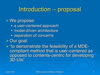
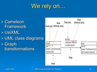
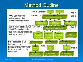
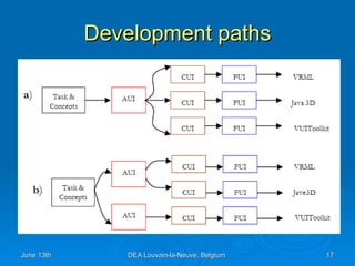
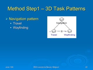
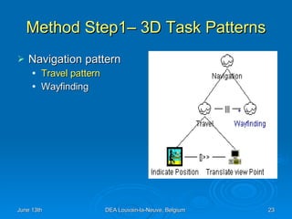
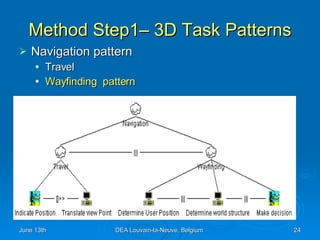
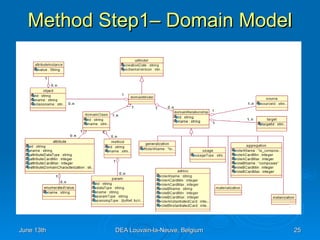
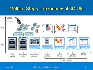
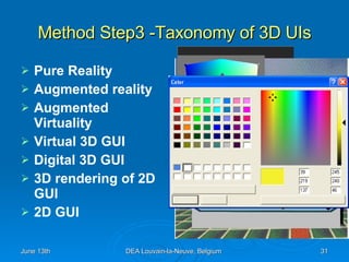
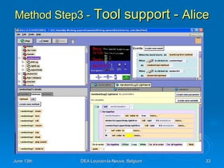
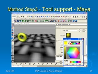
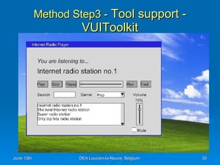
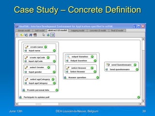
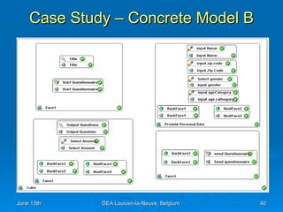
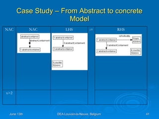
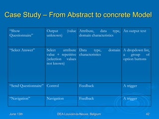
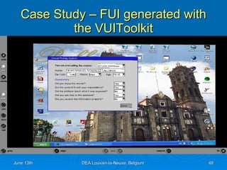
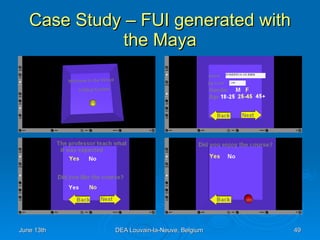
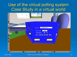
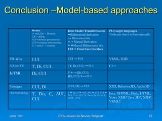
A model-based development for 3D User Interfaces Juan Manuel Gonzalez Calleros Université catholique de Louvain,  School   of  Management (IAG) Information  Systems  Unit (ISYS) Louvain-la-Neuve, 13th  June , 2006
Contents Introduction Related Work Model-based development for 3D User Interfaces Case Study Conclusion
Introduction - Problem Current methods: rarely provide the design knowledge are more focusing on the implementation Available tools for 3D UIs are: Toolkits, interface builders, rendering engines
Introduction – proposal We propose: a user-centered approach model-driven architecture separation of concerns Our goal: “to demonstrate the feasibility of a MDE-compliant method that is user-centered as opposed to contents-centric for developing 3D UIs”
Contents Introduction Related Work Model-based development for 3D User Interfaces Case Study Conclusion
Related work – 3D UIs generation Programmatic approach:  OpenGL, Direct3D, C++, MCNL, VRML, X3D, …  Toolkit programming:  Maya, Max3D, Crazy Eddie's GUI System, Anark, Alice Render engines:  Microsoft task gallery, infinite 3D Cube, Sphere XP, looking glass, Clara browser, 3DNA Model based:  ontoWEb (VR-Wise), ConGenIVE (VRIXML), InTML, Contigra
Related work – Programmatic Approach, VRML
Related work – Toolkit  Approach, Anark
Related work – Render Engines, 3DNA
Related work – Model-based approach, CoGenIVE-VRIXML < GroupItem   > < UISlider  paramID  =&quot; 10 &quot;> < Value  min  =&quot; 0 &quot;   max =&quot; 255 &quot;/> < Tickstyle   orientation  =&quot;  horizontal “  position  =&quot;  both  &quot;   frequency  =&quot; 16 &quot;/> </  UISlider  > < Position   > < X > 1.0  </ X >< Y > 1.5  </ Y > </  Position  > </  GroupItem  >
Related work – Observations Methodological diversity  Not user centered approaches Single entry and single output  Transformations are hidden
Related work – Shortcomings Lack of a methodology for developing 3D UIs Lack of user task models Lack of models independent to the final implementations Lack of a toolkit for such work Lack of genuine 3D UIs
Contents Introduction Related work Model-based development for 3D User Interfaces Case Study Conclusion
Model-based development of 3DUIs requirements Expressivity   Machine processable   Human readable   Methodological explicitness,   flexibility, separation of concerns
We rely on… Cameleon Framework UsiXML UML class diagrams Graph transformations
Method Outline
Development paths
Graph transformation tool support AGG
Method Step1 – Task and concepts description
Method Step1 - User Action Task Extension The action of identifying any user action Perceive The action of mediate user actions Mediate The action to communicate the user to the system or vice versa Communicate The existence of two different states of an item Toggle An action of modifying an item Modify Specifies the creation an item Create Specifies some sort of indication Indicate Specifies the end to an action Terminate Specifies the triggers of an action Trigger Definition actionType
Method Step1– 3D Task Patterns A pattern is not a finished design that can be transformed directly into code  It is a description or template for how to solve a problem that can be used in many different situations  We propose some patterns for common 3D user tasks
Method Step1 – 3D Task Patterns Navigation pattern Travel Wayfinding
Method Step1– 3D Task Patterns Navigation pattern Travel pattern Wayfinding
Method Step1– 3D Task Patterns Navigation pattern Travel Wayfinding  pattern
Method Step1– Domain Model
Method Step1 – Software tool
Method Step2 – Abstract Model An  Abstract Individual Component   ( AIC ) is an abstraction that allows the description of interaction objects in a way that is independent of the modality  An  Abstract Container  (AC) is an entity allowing a logical grouping of other abstract containers or abstract individual components.
Method Step2 – Tool support
Method Step3 –To obtain a Concrete specification
Method Step3 –Taxonomy of 3D UIs
Method Step3 -Taxonomy of 3D UIs Pure Reality Augmented reality Augmented Virtuality Virtual 3D GUI Digital 3D GUI 3D rendering of 2D GUI 2D GUI
Method Step3 -  Lesson learnt from   Taxonomy Source of inspiration Abstract characteristics  Design options Gaps to fulfill Concrete User Interface Model
Method Step3 -  Tool support -  Alice
Method Step3 -  Tool support - Maya
Method Step3 -  Tool support - VUIToolkit
Method Step4 – Final User Interface VRML X3D Java 3D
Contents Introduction Related Work Model-based development for 3D User Interfaces Case Study Conclusion
Case Study – Task and domain definition
Case Study – Concrete Definition
Case Study – Concrete Model B
Case Study – From Abstract to concrete Model x>2 RHS := LHS NAC NAC
Case Study – From Abstract to concrete Model A trigger Feedback Navigation “ Navigation” A trigger Feedback  Control “ Send Questionnaire” A dropdown list, a group of option buttons  Data type, domain characteristics  Select attribute value + repetitive (selection values not known)  “ Select Answer” An output text Attribute, data type, domain characteristics Output  (value unknown)  “ Show Questionnaire”
Mock-up of the Concrete User Interface
Case Study – From Abstract to concrete Model < Group > < CubeFace  id =&quot; C1 &quot;> < SphereTrigger  defaultContent =&quot; Start &quot;   radious =&quot; 1.5 &quot;  solid =&quot; True &quot;  isVisible =&quot; true &quot;   isEnabled =&quot; true &quot;> < Transform  scale =&quot; 8.23 8.23 8.23 &quot;   translation =&quot; 0.27 12.14  18.30 &quot;/> < TouchSensor  id =&quot; TS1 &quot;  enabled =&quot; True &quot;/> < Appearance  name =&quot; ButtonAppe &quot;     id =&quot; App1 &quot;> < Material   diffuseColor =&quot; 0.8 0.8 0.0 &quot;     specularColor =&quot; 0.11 0.11 0.11 &quot;   emissiveColor =&quot; 0.0 0.0 0.0 &quot;   shininess =&quot; 0.3 &quot;/> </ Appearance > </ SphereTrigger > </ Group >
Case Study – Editing the FUI in Maya
Case Study – Editing the FUI in Alice
Case Study – FUI generated with Alice
Case Study – FUI generated with the VUIToolkit
Case Study – FUI generated with the Maya
Use of the virtual polling system Case Study in a virtual world
Contents Introduction Related Work Model-based development for 3D User Interfaces Case Study Conclusion
Conclusion –Model-based approaches Java, XHTML, Flash, HTML,  Voice XML* Java 3D*, X3D*, VRML*.  T     Do, T     AUI, AUI     CUI, CUI    AUI, T     CUI, (T, Do,AUI,CUI)     C, CUI ≈ ->  FUI T, Do, C, AUI, CUI  Our methodology X3D, Behavior3D, Audio3D (CUI, Di) -> FUI CUI, Di Contigra T  ≈-> ( Di, CUI),  ( Di, CUI)  ≈ -> FUI Di, CUI InTML C++ ( T, Di, CUI )     FUI T, Di, CUI CoGenIVE VRML, X3D CUI -> FUI CUI  VR-Wise FUI target languages *Indicates that it is done manually Inter Model Transformation    Bidirectional derivation ->   Derivation link ≈->   Manual Derivation ≈     Manual Bidirectional der. FUI = Final User Interface Models t= task, Do = Domain Di = dialog  AUI=abstract presentation  CUI=concrete user interface  U = user, C = context.
Conclusion The method based on graph transformation  has been introduced, defined and illustrated  We proposed a method for 3D UI development whose life cycle was divided into four steps ranging from the most abstract to the most concretes according to the principles of Model-Driven Engineering. The feasibility of the approach is much depending on the amount and the quality of the design rules that are encoded in UsiXML.
Conclusion Future work.  Exploring more design options and encode them in UsiXML  Models Transformational rules Software tools More FUI  Consolidate concepts
Thank you Juan Manuel Gonzalez Calleros

Model Based Development For 3 D User Interfaces

  • 1.
    A model-based developmentfor 3D User Interfaces Juan Manuel Gonzalez Calleros Université catholique de Louvain, School of Management (IAG) Information Systems Unit (ISYS) Louvain-la-Neuve, 13th June , 2006
  • 2.
    Contents Introduction RelatedWork Model-based development for 3D User Interfaces Case Study Conclusion
  • 3.
    Introduction - ProblemCurrent methods: rarely provide the design knowledge are more focusing on the implementation Available tools for 3D UIs are: Toolkits, interface builders, rendering engines
  • 4.
    Introduction – proposalWe propose: a user-centered approach model-driven architecture separation of concerns Our goal: “to demonstrate the feasibility of a MDE-compliant method that is user-centered as opposed to contents-centric for developing 3D UIs”
  • 5.
    Contents Introduction RelatedWork Model-based development for 3D User Interfaces Case Study Conclusion
  • 6.
    Related work –3D UIs generation Programmatic approach: OpenGL, Direct3D, C++, MCNL, VRML, X3D, … Toolkit programming: Maya, Max3D, Crazy Eddie's GUI System, Anark, Alice Render engines: Microsoft task gallery, infinite 3D Cube, Sphere XP, looking glass, Clara browser, 3DNA Model based: ontoWEb (VR-Wise), ConGenIVE (VRIXML), InTML, Contigra
  • 7.
    Related work –Programmatic Approach, VRML
  • 8.
    Related work –Toolkit Approach, Anark
  • 9.
    Related work –Render Engines, 3DNA
  • 10.
    Related work –Model-based approach, CoGenIVE-VRIXML < GroupItem > < UISlider paramID =&quot; 10 &quot;> < Value min =&quot; 0 &quot; max =&quot; 255 &quot;/> < Tickstyle orientation =&quot; horizontal “ position =&quot; both &quot; frequency =&quot; 16 &quot;/> </ UISlider > < Position > < X > 1.0 </ X >< Y > 1.5 </ Y > </ Position > </ GroupItem >
  • 11.
    Related work –Observations Methodological diversity Not user centered approaches Single entry and single output Transformations are hidden
  • 12.
    Related work –Shortcomings Lack of a methodology for developing 3D UIs Lack of user task models Lack of models independent to the final implementations Lack of a toolkit for such work Lack of genuine 3D UIs
  • 13.
    Contents Introduction Relatedwork Model-based development for 3D User Interfaces Case Study Conclusion
  • 14.
    Model-based development of3DUIs requirements Expressivity Machine processable Human readable Methodological explicitness, flexibility, separation of concerns
  • 15.
    We rely on…Cameleon Framework UsiXML UML class diagrams Graph transformations
  • 16.
  • 17.
  • 18.
  • 19.
    Method Step1 –Task and concepts description
  • 20.
    Method Step1 -User Action Task Extension The action of identifying any user action Perceive The action of mediate user actions Mediate The action to communicate the user to the system or vice versa Communicate The existence of two different states of an item Toggle An action of modifying an item Modify Specifies the creation an item Create Specifies some sort of indication Indicate Specifies the end to an action Terminate Specifies the triggers of an action Trigger Definition actionType
  • 21.
    Method Step1– 3DTask Patterns A pattern is not a finished design that can be transformed directly into code It is a description or template for how to solve a problem that can be used in many different situations We propose some patterns for common 3D user tasks
  • 22.
    Method Step1 –3D Task Patterns Navigation pattern Travel Wayfinding
  • 23.
    Method Step1– 3DTask Patterns Navigation pattern Travel pattern Wayfinding
  • 24.
    Method Step1– 3DTask Patterns Navigation pattern Travel Wayfinding pattern
  • 25.
  • 26.
    Method Step1 –Software tool
  • 27.
    Method Step2 –Abstract Model An Abstract Individual Component ( AIC ) is an abstraction that allows the description of interaction objects in a way that is independent of the modality An Abstract Container (AC) is an entity allowing a logical grouping of other abstract containers or abstract individual components.
  • 28.
    Method Step2 –Tool support
  • 29.
    Method Step3 –Toobtain a Concrete specification
  • 30.
  • 31.
    Method Step3 -Taxonomyof 3D UIs Pure Reality Augmented reality Augmented Virtuality Virtual 3D GUI Digital 3D GUI 3D rendering of 2D GUI 2D GUI
  • 32.
    Method Step3 - Lesson learnt from Taxonomy Source of inspiration Abstract characteristics Design options Gaps to fulfill Concrete User Interface Model
  • 33.
    Method Step3 - Tool support - Alice
  • 34.
    Method Step3 - Tool support - Maya
  • 35.
    Method Step3 - Tool support - VUIToolkit
  • 36.
    Method Step4 –Final User Interface VRML X3D Java 3D
  • 37.
    Contents Introduction RelatedWork Model-based development for 3D User Interfaces Case Study Conclusion
  • 38.
    Case Study –Task and domain definition
  • 39.
    Case Study –Concrete Definition
  • 40.
    Case Study –Concrete Model B
  • 41.
    Case Study –From Abstract to concrete Model x>2 RHS := LHS NAC NAC
  • 42.
    Case Study –From Abstract to concrete Model A trigger Feedback Navigation “ Navigation” A trigger Feedback Control “ Send Questionnaire” A dropdown list, a group of option buttons Data type, domain characteristics Select attribute value + repetitive (selection values not known) “ Select Answer” An output text Attribute, data type, domain characteristics Output (value unknown) “ Show Questionnaire”
  • 43.
    Mock-up of theConcrete User Interface
  • 44.
    Case Study –From Abstract to concrete Model < Group > < CubeFace id =&quot; C1 &quot;> < SphereTrigger defaultContent =&quot; Start &quot; radious =&quot; 1.5 &quot; solid =&quot; True &quot; isVisible =&quot; true &quot; isEnabled =&quot; true &quot;> < Transform scale =&quot; 8.23 8.23 8.23 &quot; translation =&quot; 0.27 12.14 18.30 &quot;/> < TouchSensor id =&quot; TS1 &quot; enabled =&quot; True &quot;/> < Appearance name =&quot; ButtonAppe &quot; id =&quot; App1 &quot;> < Material diffuseColor =&quot; 0.8 0.8 0.0 &quot; specularColor =&quot; 0.11 0.11 0.11 &quot; emissiveColor =&quot; 0.0 0.0 0.0 &quot; shininess =&quot; 0.3 &quot;/> </ Appearance > </ SphereTrigger > </ Group >
  • 45.
    Case Study –Editing the FUI in Maya
  • 46.
    Case Study –Editing the FUI in Alice
  • 47.
    Case Study –FUI generated with Alice
  • 48.
    Case Study –FUI generated with the VUIToolkit
  • 49.
    Case Study –FUI generated with the Maya
  • 50.
    Case Study –FUI generated with the Maya
  • 51.
    Use of thevirtual polling system Case Study in a virtual world
  • 52.
    Contents Introduction RelatedWork Model-based development for 3D User Interfaces Case Study Conclusion
  • 53.
    Conclusion –Model-based approachesJava, XHTML, Flash, HTML, Voice XML* Java 3D*, X3D*, VRML*. T  Do, T  AUI, AUI  CUI, CUI  AUI, T  CUI, (T, Do,AUI,CUI)  C, CUI ≈ -> FUI T, Do, C, AUI, CUI Our methodology X3D, Behavior3D, Audio3D (CUI, Di) -> FUI CUI, Di Contigra T ≈-> ( Di, CUI), ( Di, CUI) ≈ -> FUI Di, CUI InTML C++ ( T, Di, CUI )  FUI T, Di, CUI CoGenIVE VRML, X3D CUI -> FUI CUI VR-Wise FUI target languages *Indicates that it is done manually Inter Model Transformation  Bidirectional derivation -> Derivation link ≈-> Manual Derivation ≈  Manual Bidirectional der. FUI = Final User Interface Models t= task, Do = Domain Di = dialog AUI=abstract presentation CUI=concrete user interface U = user, C = context.
  • 54.
    Conclusion The methodbased on graph transformation has been introduced, defined and illustrated We proposed a method for 3D UI development whose life cycle was divided into four steps ranging from the most abstract to the most concretes according to the principles of Model-Driven Engineering. The feasibility of the approach is much depending on the amount and the quality of the design rules that are encoded in UsiXML.
  • 55.
    Conclusion Future work. Exploring more design options and encode them in UsiXML Models Transformational rules Software tools More FUI Consolidate concepts
  • 56.
    Thank you JuanManuel Gonzalez Calleros