Advanced
Compu=ng
and
Op=miza=on
Infrastructure
for
Extremely
Large-‐Scale
Graphs
on
Post
Peta-‐Scale
Supercomputers
• JST(Japan
Science
and
Technology
Agency)
CREST(Core
Research
for
Evoluonal
Science
and
Technology)
Project
(Oct,
2011
䡚㻌
March,
2017)
• 4
groups,
over
60
members
1. Fujisawa-‐G
(Kyushu
University)
:
Large-‐scale
Mathemacal
Opmizaon
2. Suzumura-‐G
(University
College
Dublin,
Ireland)
:
Large-‐scale
Graph
Processing
3. Sato-‐G
(Tokyo
Instute
of
Technology)
:
Hierarchical
Graph
Store
System
4. Wakita-‐G
(Tokyo
Instute
of
Technology)
:
Graph
Visualizaon
• Innova=ve
Algorithms
and
implementa=ons
• Opmizaon,
Searching,
Clustering,
Network
flow,
etc.
• Extreme
Big
Graph
Data
for
emerging
applicaons
• 230
~
242
nodes
and
240
~
246
edges
• Over
1M
threads
are
required
for
real-‐me
analysis
• Many
applicaons
on
post
peta-‐scale
supercomputers
• Analyzing
massive
cyber
security
and
social
networks
• Opmizing
smart
grid
networks
• Health
care
and
medical
science
• Understanding
complex
life
system
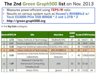
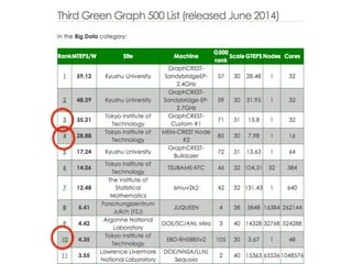
The 2nd GreenGraph500 list on Nov. 2013
• Measures power-efficient using TEPS/W ratio
• Results on various system such as Huawei’s RH5885v2 w/
Tecal ES3000 PCIe SSD 800GB * 2 and 1.2TB * 2
• http://green.graph500.org
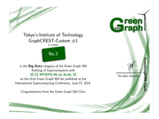
30.
Tokyo’s Institute ofTechnology
GraphCREST-Custom #1
is ranked
No.3
in the Big Data category of the Green Graph 500
Ranking of Supercomputers with
35.21 MTEPS/W on Scale 31
on the third Green Graph 500 list published at the
International Supercomputing Conference, June 23, 2014.
Congratulations from the Green Graph 500 Chair
31.
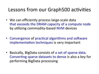
Lessons
from
our
Graph500
acvies
• We
can
efficiently
process
large-‐scale
data
that
exceeds
the
DRAM
capacity
of
a
compute
node
by
ulizing
commodity-‐based
NVM
devices
• Convergence
of
praccal
algorithms
and
sodware
implementaon
techniques
is
very
important
• Basically,
BigData
consists
of
a
set
of
sparse
data.
Converng
sparse
datasets
to
dense
is
also
a
key
for
performing
BigData
processing
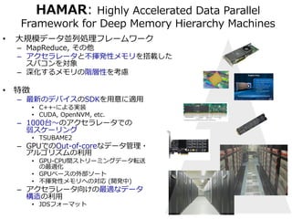
Hamar
Overview
Rank
0 Rank
1 Rank
n
Map
Local
Array Local
Array Local
Array Local
Array
Distributed
Array
Reduce
Map
Reduce
Map
Reduce
Shuffle
Shuffle
Data
Transfer
between
ranks
Shuffle
Shuffle
Local
Array Local
Array Local
Array Local
Array
Local
Array
on
NVM Local
Array
on
NVM Local
Device(GPU)
Data
Host(CPU)
Data Memcpy
(H2D,
Array
on
NVMVirtualizedL
oDcaalt
Aar
rOayb
ojne
NcVtM
D2H)
34.
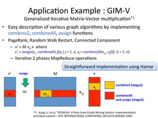
Applicaon
Example
:
GIM-‐V
Generalized
Iterave
Matrix-‐Vector
mulplicaon*1
• Easy
descripon
of
various
graph
algorithms
by
implemenng
combine2,
combineAll,
assign
funcons
• PageRank,
Random
Walk
Restart,
Connected
Component
– v’
=
M
×G
v
where
v’i
=
assign(vj
,
combineAllj
({xj
|
j
=
1..n,
xj
=
combine2(mi,j,
vj)}))
(i
=
1..n)
– Iterave
2
phases
MapReduce
operaons
Straighporward
implementaon
using
Hamar
v’ 䠙 ×G i mi,j
vj
v’ M
combine2
(stage1)
combineAll
and
assign
(stage2)
assign v
*1
:
Kang,
U.
et
al,
“PEGASUS:
A
Peta-‐Scale
Graph
Mining
System-‐
Implementaon
and
Observaons”,
IEEE
INTERNATIONAL
CONFERENCE
ON
DATA
MINING
2009
35.
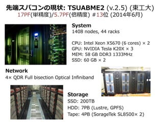
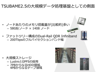
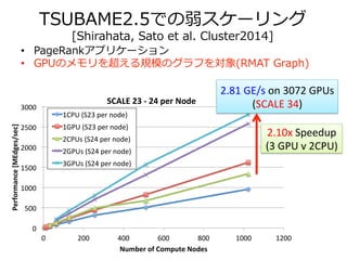
TSUBAME2.5での弱スケーリング
[Shirahata, Satoet al. Cluster2014]
• PageRankアプリケーション
• GPUのメモリを超える規模のグラフを対象(RMAT Graph)
3000
SCALE
23
-‐
24
per
Node
Performance
[MEdges/sec] Number
2500
2000
1500
1000
500
0
0
200
400
600
800
1000
1200
of
Compute
Nodes
1CPU
(S23
per
node)
1GPU
(S23
per
node)
2CPUs
(S24
per
node)
2GPUs
(S24
per
node)
3GPUs
(S24
per
node)
2.81
GE/s
on
3072
GPUs
(SCALE
34)
2.10x
Speedup
(3
GPU
v
2CPU)
36.
GPUアクセラレータと不揮発性メモリを考慮した
reliable storagedesigns for resilient extreme scale computing.
I/O構成法 [Shirahata, Sato et al. HPC141]
3.2 Burst Buffer System
To solve the problems in a flat buffer system, we consider a
burst buffer system [21]. A burst buffer is a storage space to
bridge the gap in latency and bandwidth between node-local stor-age
16
ᯛ䛾㻌mSATA
SSD
䜢⏝䛔䛯䝥䝻䝖䝍䜲䝥䝬䝅䞁䛾タィ
and the PFS, and is shared by a subset of compute nodes.
Although additional nodes are required, a burst ᐜ㔞:
256GB
x
16ᯛ
→
4TB
buffer can offer
a system many advantages including higher reliability and effi-ciency
Read䝞䞁䝗ᖜ:
0.5GB/s
x
16ᯛ
→
over a flat buffer system. A burst buffer system is more
reliable for checkpointing because burst buffers are located on
a smaller number of dedicated I/O nodes, so the probability of
lost checkpoints is decreased. In addition, even if a large number
of compute nodes fail concurrently, an application can still ac-cess
the checkpoints from the burst buffer. A burst buffer system
provides more efficient utilization of storage resources for partial
restart of uncoordinated checkpointing because processes involv-ing
restart can exploit higher storage bandwidth. For example, if
compute node 1 and 3 are in the same cluster, and both restart
from a failure, the processes can utilize all SSD bandwidth unlike
a flat buffer system. This capability accelerates the partial restart
of uncoordinated checkpoint/restart.
Table 1 Node specification
CPU Intel Core i7-3770K CPU (3.50GHz x 4 cores)
Memory Cetus DDR3-1600 (16GB)
M/B GIGABYTE GA-Z77X-UD5H
SSD Crucial m4 msata 256GB CT256M4SSD3
(Peak read: 500MB/s, Peak write: 260MB/s)
SATA converter KOUTECH IO-ASS110 mSATA to 2.5’ SATA
Device Converter with Metal Fram
RAID Card Adaptec RAID 7805Q ASR-7805Q Single
8
GB/s
A
single
mSATA
SSD
8
integrated
mSATA
SSDs
RAID
cards
Prototype/Test
machine


![㻝㻠
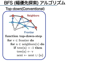
Hybrid BFS アルゴリズム [Beamer2012]
Top-down(Conventional) Bottom-up](https://image.slidesharecdn.com/memoryplusworkshop20140917-140925041805-phpapp02/85/MemoryPlus-Workshop-14-320.jpg)
![高速なBFSアルゴリズム
[Beamer2012] Beamer, S. et al.:Direction-optimizing breadth-first search, SC '12](https://image.slidesharecdn.com/memoryplusworkshop20140917-140925041805-phpapp02/85/MemoryPlus-Workshop-15-320.jpg)
![Hybrid BFS アルゴリズム [Beamer 2012]
Top-down(従来型) Bottom-up](https://image.slidesharecdn.com/memoryplusworkshop20140917-140925041805-phpapp02/85/MemoryPlus-Workshop-16-320.jpg)
![NUMAアーキテクチャに最適化された
Hybrid-‐‑‒BFS実装 [Yasui2013]
• グラフ分割をNUMAに最適化することで
メモリアクセスを⾼高速化
– アプローチ毎に最適なグラフ形状を保持 (CSR形式)
• Top-‐‑‒down → FG (forward graph)
• Bottom-‐‑‒up → BG (backward graph)
– BFS Status
• ビットマップ、キューなど
Dualモデル(⾼高性能)
BFS Status
FG
Top-‐‑‒down
(forward graph)
BG
Bottom-‐‑‒up
(backward graph)
Singleモデル(省省メモリ)
BFS Status
Top-‐‑‒down
Bottom-‐‑‒up
BG
(backward graph)
データ量量は指数的に増加
1600
1400
1200
1000
800
600
400
200
0
FGBG
26
28
30
32
SCALE
Data Size(GB)](https://image.slidesharecdn.com/memoryplusworkshop20140917-140925041805-phpapp02/85/MemoryPlus-Workshop-19-320.jpg)
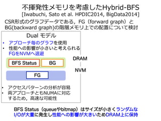
![不不揮発性メモリを考慮したHybrid-‐‑‒BFS
[Iwabuchi, Sato et al. HPDIC2014, BigData2014]
CSR形式のグラフデータである,FG(forward graph)と
BG(backward graph)の階層メモリ上での配置について検討
Dual モデル
• アプローチ毎のグラフを使用
• 性能への影響が小さいと考えられる
FGをNVMへ退避
BFS Status
FG
BG
• アクセスパターンの分析が容易易
• 両アプローチともNUMAに対応
するため,⾼高速な可能性
DRAM
NVM
BFS Status(queueやbitmap)はサイズが小さくランダムな
I/Oが大量に発生し性能への影響が大きいためDRAM上に保持](https://image.slidesharecdn.com/memoryplusworkshop20140917-140925041805-phpapp02/85/MemoryPlus-Workshop-20-320.jpg)
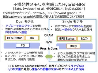
![不不揮発性メモリを考慮したHybrid-‐‑‒BFS
[Sato, Iwabuchi et al. HPDIC2014, BigData2014]
CSR形式のグラフデータである,FG(forward graph)と
BG(backward graph)の階層メモリ上での配置について検討
Single モデル
BFS Status
Dual モデル
BFS Status
FG
BG BG①
BG②
• アプローチ毎のグラフを使用
• 性能への影響が小さいと考えられる
FGをNVMへ退避
• 両アプローチでBGのみを使用
• BGは一部のみDRAM上に保持
• アクセスパターンの分析が容易易
• 両アプローチともNUMAに対応
するため,⾼高速な可能性
• より⼤大規模なグラフを実⾏行行可能
• デバイスの性能を考慮した
柔軟な容量量の変更更が可能
DRAM
NVM
Pros Cons
BFS Status(queueやbitmap)はサイズが小さくランダムな
I/Oが大量に発生し性能への影響が大きいためDRAM上に保持](https://image.slidesharecdn.com/memoryplusworkshop20140917-140925041805-phpapp02/85/MemoryPlus-Workshop-21-320.jpg)
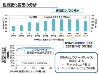
![19
グラフデータの退避手法
各頂点毎に一定数のエッジのみをDRAMに保持し
残りは不揮発性メモリ(NVM)に保持する
Graph Data(CSR-format)
0 1 2
DRAM
BG①
NVM
BG②
頂点 ID
エッジ (隣隣接先の頂点ID)の並び
DRAM NVM
BG②
BFS Status
Top-downアプローチ,
Bottom-upアプローチの
必要時にNVMから読込
(4KB)
BG①
• 細粒粒度度なI/Oと
• Bottom-upの⼤大半は
DRAM内で終える
隣隣接先頂点の次数が⼤大き
いものから優先的に
DRAMに配置
[yasui2013]](https://image.slidesharecdn.com/memoryplusworkshop20140917-140925041805-phpapp02/85/MemoryPlus-Workshop-22-320.jpg)

![TSUBAME2.5での弱スケーリング
[Shirahata, Sato et al. Cluster2014]
• PageRankアプリケーション
• GPUのメモリを超える規模のグラフを対象(RMAT Graph)
3000
SCALE
23
-‐
24
per
Node
Performance
[MEdges/sec] Number
2500
2000
1500
1000
500
0
0
200
400
600
800
1000
1200
of
Compute
Nodes
1CPU
(S23
per
node)
1GPU
(S23
per
node)
2CPUs
(S24
per
node)
2GPUs
(S24
per
node)
3GPUs
(S24
per
node)
2.81
GE/s
on
3072
GPUs
(SCALE
34)
2.10x
Speedup
(3
GPU
v
2CPU)](https://image.slidesharecdn.com/memoryplusworkshop20140917-140925041805-phpapp02/85/MemoryPlus-Workshop-35-320.jpg)
![GPUアクセラレータと不揮発性メモリを考慮した
reliable storage designs for resilient extreme scale computing.
I/O構成法 [Shirahata, Sato et al. HPC141]
3.2 Burst Buffer System
To solve the problems in a flat buffer system, we consider a
burst buffer system [21]. A burst buffer is a storage space to
bridge the gap in latency and bandwidth between node-local stor-age
16
ᯛ䛾㻌mSATA
SSD
䜢⏝䛔䛯䝥䝻䝖䝍䜲䝥䝬䝅䞁䛾タィ
and the PFS, and is shared by a subset of compute nodes.
Although additional nodes are required, a burst ᐜ㔞:
256GB
x
16ᯛ
→
4TB
buffer can offer
a system many advantages including higher reliability and effi-ciency
Read䝞䞁䝗ᖜ:
0.5GB/s
x
16ᯛ
→
over a flat buffer system. A burst buffer system is more
reliable for checkpointing because burst buffers are located on
a smaller number of dedicated I/O nodes, so the probability of
lost checkpoints is decreased. In addition, even if a large number
of compute nodes fail concurrently, an application can still ac-cess
the checkpoints from the burst buffer. A burst buffer system
provides more efficient utilization of storage resources for partial
restart of uncoordinated checkpointing because processes involv-ing
restart can exploit higher storage bandwidth. For example, if
compute node 1 and 3 are in the same cluster, and both restart
from a failure, the processes can utilize all SSD bandwidth unlike
a flat buffer system. This capability accelerates the partial restart
of uncoordinated checkpoint/restart.
Table 1 Node specification
CPU Intel Core i7-3770K CPU (3.50GHz x 4 cores)
Memory Cetus DDR3-1600 (16GB)
M/B GIGABYTE GA-Z77X-UD5H
SSD Crucial m4 msata 256GB CT256M4SSD3
(Peak read: 500MB/s, Peak write: 260MB/s)
SATA converter KOUTECH IO-ASS110 mSATA to 2.5’ SATA
Device Converter with Metal Fram
RAID Card Adaptec RAID 7805Q ASR-7805Q Single
8
GB/s
A
single
mSATA
SSD
8
integrated
mSATA
SSDs
RAID
cards
Prototype/Test
machine](https://image.slidesharecdn.com/memoryplusworkshop20140917-140925041805-phpapp02/85/MemoryPlus-Workshop-36-320.jpg)
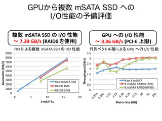
![9000
8000
7000
6000
5000
4000
3000
2000
1000
0
GPUから複数 mSATA SSD への
I/O性能の予備評価
Raw
mSATA
4KB
RAID0
1MB
RAID0
64KB
0
5
10
15
20
Bandwidth
[MB/s]
#
mSATAs
3.5
3
2.5
2
1.5
1
0.5
0
Throughuput
[GB/s]
Raw
8
mSATA
8
mSATA
RAID0
(1MB)
8
mSATA
RAID0
(64KB)
Matrix
Size
[GB]
FIO
䛻䜘䜛」ᩘ㻌mSATA
SSD
䛾
I/O
ᛶ⬟ ⾜ิ䝧䜽䝖䝹✚䛻䜘䜛
GPU
䜈䛾
I/O
ᛶ⬟
」ᩘ㻌mSATA
SSD
䛾
I/O
ᛶ⬟
ࠥ
7.39
GB/s
(RAID0
䜢⏝)
GPU
䜈䛾
I/O
ᛶ⬟
ࠥ
3.06
GB/s
(PCI-‐E
ୖ㝈)](https://image.slidesharecdn.com/memoryplusworkshop20140917-140925041805-phpapp02/85/MemoryPlus-Workshop-37-320.jpg)
![[20170922 Sapporo Tech Bar] 地図用データを高速処理!オープンソースGPUデータベースMapDってどんなもの?? by 株式会社...](https://cdn.slidesharecdn.com/ss_thumbnails/20170922mapd-170926064811-thumbnail.jpg?width=640&height=640&fit=bounds)


![[db tech showcase Tokyo 2017] B35: 地図用データを高速処理!オープンソースGPUデータベースMapDの魅力に迫る!!by...](https://cdn.slidesharecdn.com/ss_thumbnails/b35-170912021017-thumbnail.jpg?width=640&height=640&fit=bounds)


![[db tech showcase Tokyo 2017] D33: Deep Learningや、Analyticsのワークロードを加速するには-Ten...](https://cdn.slidesharecdn.com/ss_thumbnails/d33-170912071011-thumbnail.jpg?width=640&height=640&fit=bounds)

![[DDBJing31] 軽量仮想環境を用いてNGSデータの解析再現性を担保する](https://cdn.slidesharecdn.com/ss_thumbnails/31ddbjingohta-150626022623-lva1-app6892-thumbnail.jpg?width=640&height=640&fit=bounds)