Download to read offline
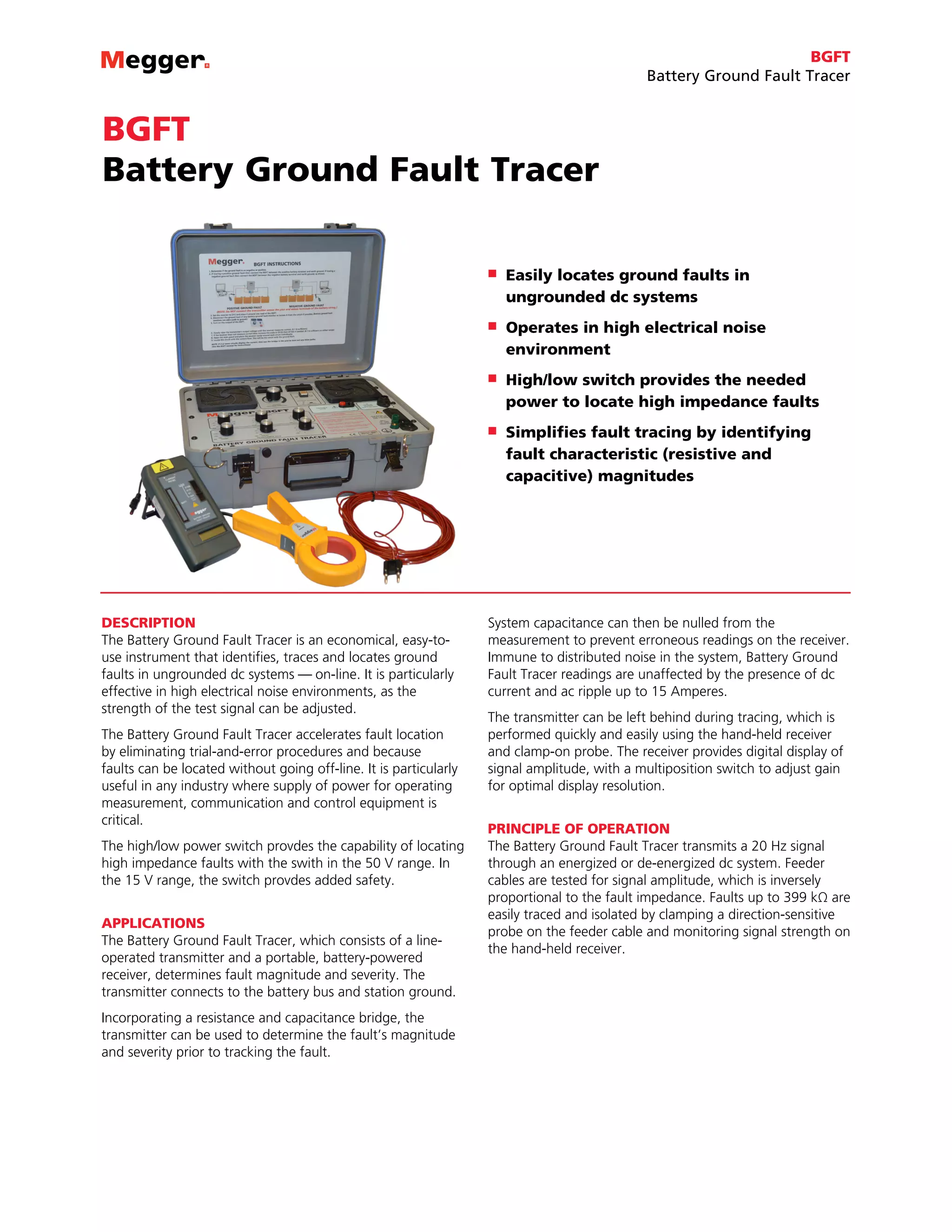
![BGFT
Battery Ground Fault Tracer
FEATURES AND BENEFITS
n Digital display of voltage and current signal amplitudes
n Bridge measurement of fault resistance and system
capacitance. (The use of the bridge is optional.)
n Wide fault resistance measurement range from 1 kΩ to 399 kΩ
n Immune to distributed noise
n Soft-start charging system to prevent sensitive relay
tripping
n Convenient, hand-held receiver
n Receiver gain control for optimal display resolution
SPECIFICATIONS
Power Source
Transmitter
246100C: 115 V AC ±10% @ 50/60Hz, 200 VA max
246100C-47: 230 V AC ±10% @ 50/60Hz, 200 VA max
Receiver: One 9-volt alkaline battery supplies up to 40 hours
continuous use at 20oC (estimated).
Source Voltage
Variable from 0 to 15 V rms in low range
Variable from 0 to 50 V rms in high range
Source Current
Load dependent from 0 to 1.7 A rms
Source Frequency
20 Hz, ±2%
Fault Resistance
1 kΩ to 399 kΩ at 50 V; bridge accuracy ±10%
Line Capacitance
0.01 to 11.1 µF; bridge accuracy ±20%
Display
Transmitter: Separate 3-digit LCD meters for volts and current
Accuracy: ±5%
Receiver: Digital meter display up to 1.999 (three gain selections)
Temperature Range
Operating: 32 to 105° F (0 to 40° C)
Storage: -5 to +130° F (-20 to +55° C)
Dimensions
Transmitter
7.5 H x 18.5 W x 14.6 D in. (19 H x 47 W x 37 D cm)
Receiver
1.5 H x 3.5 W x 7.5 D in. (4 H x 9 W x 19 D cm)
Weight
Transmitter: 35 lb (15.9 kg)
Receiver: 0.66 lb (0.3 kg)
Item (Qty) Cat. No.
Dual-range Battery Ground Fault Tracer,120 V AC, 50/60 Hz, CE-marked 246100C
Dual-range Battery Ground Fault Tracer, 230 V AC, 50/60 Hz, CE-marked 246100C-47
Included Accessories
Fused source leads with interchangeable clamps, 20 ft (6 m) [1 pr] 29386-5
Current transformer, 2 in. (5 cm) with leads, 4 ft (1.2 mm) [1 pr] 29999-1
US - AC power cord (with C/N 247100C only) [1] 17032
UK - AC power cord (with C/N 247100C-47 only) [1] 17032-12
EU - AC power cord (with C/N 247100C only) [1] 17032-13
Feedback cable, 40 ft (12 m) [1] 29998
Padded accessory bag [1] 29996
Battery, 9 volt [1] 1482-1
Operator’s manual [1] AVTM246100C
Optional Accessories
Mini-CT, 0.5 in. (12 mm) with 4.25 ft (1.3 m) lead 30595
Ordering Information
UK
Archcliffe Road, Dover
CT17 9EN England
T +44 (0) 1 304 502101
F +44 (0) 1 304 207342
UKsales@megger.com
United States
4271 Bronze Way
Dallas, TX 75237-1019 USA
T 1 800 723 2861 (USA only)
T +1 214 333 3201
F +1 214 331 7399
USsales@megger.com
Other technical sales offices
Valley Forge USA, College Station
USA, Sydney AUSTRALIA, Täby
SWEDEN, Ontario CANADA, Trappes
FRANCE, Oberursel GERMANY, Aargau
SWITZERLAND, Kingdom of BAHRAIN,
Mumbai INDIA, Johannesburg SOUTH
AFRICA, and Chonburi THAILAND
ISO STATEMENT
Registered to ISO 9001:2008 Cert. no. 110006.01
BGFT_DS_en_V14
www.megger.com
Megger is a registered trademark](https://image.slidesharecdn.com/megger-bgft-battery-ground-fault-tracer-160210133821/75/Megger-BGFT-Battery-Ground-Fault-Tracer-2-2048.jpg)

The document describes a Battery Ground Fault Tracer (BGFT) which is a device that identifies, traces, and locates ground faults in ungrounded DC systems. It consists of a transmitter that connects to the battery bus and ground, and a portable receiver. The transmitter sends a 20Hz signal through the system, and faults are located by monitoring signal strength with the receiver's clamp-on probe. The BGFT can measure fault resistance from 1kΩ to 399kΩ, and is effective even in noisy environments.


