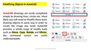
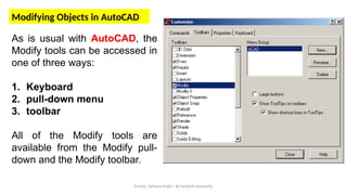
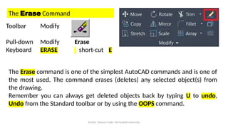
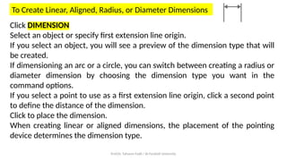
Prof.Dr. Tahseen Fadil / Al-Farahidi University
MECHANICAL DRAWING
Technical College of Engineering
Department of Refrigeration and AC
Engineering Techniques
Prof. Dr. Tahseen Fadhil
2nd
Year Refrigeration and AC Engineering
2024-2025
LECTURE 2
(22 Slides)
Prof.Dr. Tahseen Fadil / Al-Farahidi University
Modifying Objects in AutoCAD
AutoCAD drawings are rarely completed
simply by drawing lines, circles etc. Most
likely you will need to Modify these basic
drawing objects in some way in order to
create the image you need. AutoCAD
provides a whole range of modify tools
such as Move, Copy, Rotate and Mirror,
the command names are easily
understandable.
Prof.Dr. Tahseen Fadil / Al-Farahidi University
Modifying Objects in AutoCAD
As is usual with AutoCAD, the
Modify tools can be accessed in
one of three ways:
1. Keyboard
2. pull-down menu
3. toolbar
All of the Modify tools are
available from the Modify pull-
down and the Modify toolbar.
Prof.Dr. Tahseen Fadil / Al-Farahidi University
The Erase Command
Toolbar Modify
Pull-down Modify Erase
Keyboard ERASE short-cut E
The Erase command is one of the simplest AutoCAD commands and is one of
the most used. The command erases (deletes) any selected object(s) from
the drawing.
Remember you can always get deleted objects back by typing U to undo,
Undo from the Standard toolbar or by using the OOPS command.
Prof.Dr. Tahseen Fadil / Al-Farahidi University
The Copy Command
Toolbar Modify
Pull-down Modify Copy
Keyboard COPY short-cut CP
The Copy command can be used to
create one or more duplicates of any
drawing object or objects which you
have previously created.
Prof.Dr. Tahseen Fadil / Al-Farahidi University
The Mirror Command
Toolbar Modify
Pull-down Modify Mirror
Keyboard MIRROR short-cut MI
The Mirror command allows you to
mirror selected objects in your drawing
by picking them and then defining the
position of an imaginary mirror line
using two points.
Prof.Dr. Tahseen Fadil / Al-Farahidi University
The Offset Command
Toolbar Modify
Pull-down Modify Offset
Keyboard OFFSET short-cut O
Prof.Dr. Tahseen Fadil / Al-Farahidi University
The Array Command
Toolbar Modify
Pull-down Modify Array
Keyboard ARRAY short-cut AR
The illustration on the right shows the
results of a rectangular array with two
columns an three rows. The distance
between rows is indicated with the
dimension DR and between columns
with DC.
Prof.Dr. Tahseen Fadil / Al-Farahidi University
The Array Command
Try creating this array. First, draw a rectangle
20 units wide and 10 units tall. To do this,
start the rectangle command Draw
Rectangle from the pull-down menu. When
you are prompted to pick a point, pick
somewhere in the lower left quarter of the
drawing area. Then, when you are prompted
for a second point, enter the relative
cartesian co-ordinate @20,10. You have now
drawn a rectangle at the right size. See the
Using Co-ordinates tutorial for more
information on drawing with co-ordinates.
Prof.Dr. Tahseen Fadil / Al-Farahidi University
The Array Command
Click the Select objects button.
 Enter the number of rows
 Enter the number of columns
 Enter the row offset
 Enter the column offset
 Array Click on the Preview button.
You should now have an array that looks similar to the
one in the illustration consisting of 6 rectangles arranged
in 3 rows and 2 columns. As you can se, this command is
very powerful and can save lots of time if used carefully.
Prof.Dr. Tahseen Fadil / Al-Farahidi University
The Polar Array
The polar array works in a similar
way to the rectangular array. The
main difference is that rather than
specifying the number and offset for
rows and columns, you must specify
a center point and the total number
of objects in the array (including the
original object).
Prof.Dr. Tahseen Fadil / Al-Farahidi University
The Polar Array
 Click the Select objects button.
 Specify the center point for the array.
 Enter a value for the total number of items.
 ArrayClick on the Preview button.
Prof.Dr. Tahseen Fadil / Al-Farahidi University
The Move Command
Toolbar Modify
Pull-down Modify Move
Keyboard MOVEshort-cut M
Prof.Dr. Tahseen Fadil / Al-Farahidi University
The Rotate Command
Toolbar Modify
Pull-down Modify Rotate
Keyboard ROTATE short-cut RO
The Rotate command allows an object
or objects to be rotated about a point
selected by the user. AutoCAD prompts
for a second rotation point or an angle
which can be typed at the keyboard.
Prof.Dr. Tahseen Fadil / Al-Farahidi University
The Scale Command
Toolbar Modify
Pull-down Modify Scale
Keyboard SCALE short-cut SC
The Scale command can be used to
change the size of an object or group of
objects. You are prompted for a pick
point about which the selection set will
be scaled.
Prof.Dr. Tahseen Fadil / Al-Farahidi University
The Trim Command
Toolbar Modify
Pull-down Modify Trim
Keyboard TRIM short-cut TR
The Trim command can be used to trim a
part of an object. In order to trim an object
you must draw a second object which forms
the "cutting edge". Cutting edges can be
lines, polylines, circles, arcs or ellipses.
Blocks and text cannot be trimmed or used
as cutting edges.
Prof.Dr. Tahseen Fadil / Al-Farahidi University
The Extend Command
Toolbar Modify
Pull-down Modify Extend
Keyboard EXTEND short-cut EX
This command extends a line, polyline or
arc to meet another drawing object
(known as the boundary edge).
Prof.Dr. Tahseen Fadil / Al-Farahidi University
The Chamfer Command
Toolbar Modify
Pull-down Modify Chamfer
Keyboard CHAMFER short-cut CHA
The Chamfer command enables you to
create a chamfer between any two non-
parallel lines as in the illustration below
or any two adjacent polyline segments.
Usually, the Chamfer command is used
to set the chamfer distances before
drawing the chamfer.
Prof.Dr. Tahseen Fadil / Al-Farahidi University
The Fillet Command
Toolbar Modify
Pull-down Modify Fillet
Keyboard FILLET short-cut F
The Fillet command is a very useful tool
which allows you to draw an arc
between two intersecting lines or
adjacent polyline segments. You first
need to use the command to set the
required radius and then a second time
to select the two lines.
Prof.Dr. Tahseen Fadil / Al-Farahidi University
Dimensioning in AutoCAD
When you hover over an object
for dimensioning, the
DIMENSION (or DIM) command
automatically previews a
suitable dimension type to use.
Select objects, lines, or points to
dimension and click anywhere in
the drawing area to draw the
dimension.
The available dimension types are:
 vertical linear
 horizontal linear
 aligned linear
 angular
 radius
 diameter
Prof.Dr. Tahseen Fadil / Al-Farahidi University
To Create Linear, Aligned, Radius, or Diameter Dimensions
Click DIMENSION
Select an object or specify first extension line origin.
If you select an object, you will see a preview of the dimension type that will
be created.
If dimensioning an arc or a circle, you can switch between creating a radius or
diameter dimension by choosing the dimension type you want in the
command options.
If you select a point to use as a first extension line origin, click a second point
to define the distance of the dimension.
Click to place the dimension.
When creating linear or aligned dimensions, the placement of the pointing
device determines the dimension type.
Prof.Dr. Tahseen Fadil / Al-Farahidi University
THANK YOU
SEE YOU NEXT WEEK

Mechanical and Engineering Drawing with AutoCAD

  • 1.
    Prof.Dr. Tahseen Fadil/ Al-Farahidi University MECHANICAL DRAWING Technical College of Engineering Department of Refrigeration and AC Engineering Techniques Prof. Dr. Tahseen Fadhil 2nd Year Refrigeration and AC Engineering 2024-2025 LECTURE 2 (22 Slides)
  • 2.
    Prof.Dr. Tahseen Fadil/ Al-Farahidi University Modifying Objects in AutoCAD AutoCAD drawings are rarely completed simply by drawing lines, circles etc. Most likely you will need to Modify these basic drawing objects in some way in order to create the image you need. AutoCAD provides a whole range of modify tools such as Move, Copy, Rotate and Mirror, the command names are easily understandable.
  • 3.
    Prof.Dr. Tahseen Fadil/ Al-Farahidi University Modifying Objects in AutoCAD As is usual with AutoCAD, the Modify tools can be accessed in one of three ways: 1. Keyboard 2. pull-down menu 3. toolbar All of the Modify tools are available from the Modify pull- down and the Modify toolbar.
  • 4.
    Prof.Dr. Tahseen Fadil/ Al-Farahidi University The Erase Command Toolbar Modify Pull-down Modify Erase Keyboard ERASE short-cut E The Erase command is one of the simplest AutoCAD commands and is one of the most used. The command erases (deletes) any selected object(s) from the drawing. Remember you can always get deleted objects back by typing U to undo, Undo from the Standard toolbar or by using the OOPS command.
  • 5.
    Prof.Dr. Tahseen Fadil/ Al-Farahidi University The Copy Command Toolbar Modify Pull-down Modify Copy Keyboard COPY short-cut CP The Copy command can be used to create one or more duplicates of any drawing object or objects which you have previously created.
  • 6.
    Prof.Dr. Tahseen Fadil/ Al-Farahidi University The Mirror Command Toolbar Modify Pull-down Modify Mirror Keyboard MIRROR short-cut MI The Mirror command allows you to mirror selected objects in your drawing by picking them and then defining the position of an imaginary mirror line using two points.
  • 7.
    Prof.Dr. Tahseen Fadil/ Al-Farahidi University The Offset Command Toolbar Modify Pull-down Modify Offset Keyboard OFFSET short-cut O
  • 8.
    Prof.Dr. Tahseen Fadil/ Al-Farahidi University The Array Command Toolbar Modify Pull-down Modify Array Keyboard ARRAY short-cut AR The illustration on the right shows the results of a rectangular array with two columns an three rows. The distance between rows is indicated with the dimension DR and between columns with DC.
  • 9.
    Prof.Dr. Tahseen Fadil/ Al-Farahidi University The Array Command Try creating this array. First, draw a rectangle 20 units wide and 10 units tall. To do this, start the rectangle command Draw Rectangle from the pull-down menu. When you are prompted to pick a point, pick somewhere in the lower left quarter of the drawing area. Then, when you are prompted for a second point, enter the relative cartesian co-ordinate @20,10. You have now drawn a rectangle at the right size. See the Using Co-ordinates tutorial for more information on drawing with co-ordinates.
  • 10.
    Prof.Dr. Tahseen Fadil/ Al-Farahidi University The Array Command Click the Select objects button.  Enter the number of rows  Enter the number of columns  Enter the row offset  Enter the column offset  Array Click on the Preview button. You should now have an array that looks similar to the one in the illustration consisting of 6 rectangles arranged in 3 rows and 2 columns. As you can se, this command is very powerful and can save lots of time if used carefully.
  • 11.
    Prof.Dr. Tahseen Fadil/ Al-Farahidi University The Polar Array The polar array works in a similar way to the rectangular array. The main difference is that rather than specifying the number and offset for rows and columns, you must specify a center point and the total number of objects in the array (including the original object).
  • 12.
    Prof.Dr. Tahseen Fadil/ Al-Farahidi University The Polar Array  Click the Select objects button.  Specify the center point for the array.  Enter a value for the total number of items.  ArrayClick on the Preview button.
  • 13.
    Prof.Dr. Tahseen Fadil/ Al-Farahidi University The Move Command Toolbar Modify Pull-down Modify Move Keyboard MOVEshort-cut M
  • 14.
    Prof.Dr. Tahseen Fadil/ Al-Farahidi University The Rotate Command Toolbar Modify Pull-down Modify Rotate Keyboard ROTATE short-cut RO The Rotate command allows an object or objects to be rotated about a point selected by the user. AutoCAD prompts for a second rotation point or an angle which can be typed at the keyboard.
  • 15.
    Prof.Dr. Tahseen Fadil/ Al-Farahidi University The Scale Command Toolbar Modify Pull-down Modify Scale Keyboard SCALE short-cut SC The Scale command can be used to change the size of an object or group of objects. You are prompted for a pick point about which the selection set will be scaled.
  • 16.
    Prof.Dr. Tahseen Fadil/ Al-Farahidi University The Trim Command Toolbar Modify Pull-down Modify Trim Keyboard TRIM short-cut TR The Trim command can be used to trim a part of an object. In order to trim an object you must draw a second object which forms the "cutting edge". Cutting edges can be lines, polylines, circles, arcs or ellipses. Blocks and text cannot be trimmed or used as cutting edges.
  • 17.
    Prof.Dr. Tahseen Fadil/ Al-Farahidi University The Extend Command Toolbar Modify Pull-down Modify Extend Keyboard EXTEND short-cut EX This command extends a line, polyline or arc to meet another drawing object (known as the boundary edge).
  • 18.
    Prof.Dr. Tahseen Fadil/ Al-Farahidi University The Chamfer Command Toolbar Modify Pull-down Modify Chamfer Keyboard CHAMFER short-cut CHA The Chamfer command enables you to create a chamfer between any two non- parallel lines as in the illustration below or any two adjacent polyline segments. Usually, the Chamfer command is used to set the chamfer distances before drawing the chamfer.
  • 19.
    Prof.Dr. Tahseen Fadil/ Al-Farahidi University The Fillet Command Toolbar Modify Pull-down Modify Fillet Keyboard FILLET short-cut F The Fillet command is a very useful tool which allows you to draw an arc between two intersecting lines or adjacent polyline segments. You first need to use the command to set the required radius and then a second time to select the two lines.
  • 20.
    Prof.Dr. Tahseen Fadil/ Al-Farahidi University Dimensioning in AutoCAD When you hover over an object for dimensioning, the DIMENSION (or DIM) command automatically previews a suitable dimension type to use. Select objects, lines, or points to dimension and click anywhere in the drawing area to draw the dimension. The available dimension types are:  vertical linear  horizontal linear  aligned linear  angular  radius  diameter
  • 21.
    Prof.Dr. Tahseen Fadil/ Al-Farahidi University To Create Linear, Aligned, Radius, or Diameter Dimensions Click DIMENSION Select an object or specify first extension line origin. If you select an object, you will see a preview of the dimension type that will be created. If dimensioning an arc or a circle, you can switch between creating a radius or diameter dimension by choosing the dimension type you want in the command options. If you select a point to use as a first extension line origin, click a second point to define the distance of the dimension. Click to place the dimension. When creating linear or aligned dimensions, the placement of the pointing device determines the dimension type.
  • 22.
    Prof.Dr. Tahseen Fadil/ Al-Farahidi University THANK YOU SEE YOU NEXT WEEK