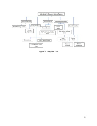
SlideShare a Scribd company logo
ME 2110 – Section A10
Final Report
Team 5:
Viraj Pahwa
Kyle Ralyea
Sohail Tariq
Junacho Valdes
Submitted to
Mr. Jacob Blevins
TA: Dr. Mighten Yip
Date: 21 April 2023
1
Abstract
The team is tasked with the design and fabrication of an automated robot intended to
competitively push, pull, deliver, and grab objects to complete core tasks with the aim of
maximizing score. The team utilized a House of Quality (HOQ) to relate customer needs and
engineering requirements, generated a function tree to detail necessary functions, and generated a
morphological chart to list potential solution mechanisms. The team then generated four unique
designs and utilized a third order evaluation matrix to quantitatively determine the best suited
design. The chosen design was explored extensively through Computer Aided Design (CAD), and
eventually fabricated for competition. The team presents an in-depth subsystem overview of this
chosen design as well as theArduino algorithm flowchart detailing the robot’s working instruction.
The team also discusses the bill of materials to ensure the team remains within budget. Finally, the
team examines the final competition’s results and generates reasoning into what went wrong.
2
Introduction
The objective of this report is to present the working subsystems of the team’s automated robot
design and discuss its final competition performance. The robot competes in an arena-style
competition, as seen in Figure 1, where it performs various tasks, each scored and tallied. The
House of Quality in Figures 2-4 and the Function Tree in Figure 5 outline these tasks. Specifically,
the robot must knock “Imperial Walkers” out of the home zone, pull “lightsabers” from quadrant
boundaries, retrieve “Baby Yoda” to behind the safety line, and insert “Proton Torpedoes” into the
“Death Star.” The Specification Sheet seen in Table 1 lists key constraints the robot design must
adhere to, which includes bounding dimensions, maximum run-time, and a strict budget. The build
must also only contain a maximum of two motors, two solenoids, and two pneumatic cylinders.
The primary engineering challenge includes the balance in choice of mechanism, space within the
robot, and choice of actuator for each mechanism. The scope of this report is to discuss the design
challenge, explore the robot’s final build and design, detail alternative designs and their drawbacks,
and finally discuss the final design’s competition performance.
Problem Understanding
Developing the team’s design tools for the robot is a crucial step in understanding how the
project will take shape. The HOQ and specification sheet focus on establishing customer
requirements and engineering specifications, then evaluating their weights. Figure 2, the customer
needs, are derived from the set of minimum requirements such as “Safety” and “Size.” It also
includes competition tasks such as “Knock Over Walker,” and implicit attributes, such as
“Aesthetically Pleasing.” The team developed engineering requirements (also shown in Figure 2),
that are reflective of the measurements and characteristics the robot must possess to meet the
customer requirements. The central portion of Figure 2 depicts many of the relationships between
the two types of requirements. For example, the height, length, and width characteristics are all
strongly related to the customers’ “Size” requirement. In addition, the team assigned quantitative
target values that are depicted in Figure 3 to each engineering requirement. This figure can be
interpreted to recognize that the three highest weighted engineering requirements are the robot’s
run time, travel distance, and risk jury measurements. This is because all functions of the robot
ultimately rely on its mobility and reliability. Therefore, the requirements that place importance
on the robot’s avoidance of disqualification are found to have the highest relative weights. These
results mean that meeting the forty-second maximum run time and limiting the robot’s risk of task
3
failure must all be held to the highest priority during design and fabrication. The next consideration
of the HOQ is the correlation between many of the important engineering requirements as seen in
Figure 4. For example, it is observed that “Setup Time” and “Risk Jury” are positively correlated,
while “Movement Speed” and “Weight” are negatively correlated.
Conceptual Design
As listed previously, the robot must complete push, pull, grab, and place tasks to be
considered competitive. Once again, the robot must knock “Imperial Walkers” out of the home
zone, pull “lightsabers” from quadrant boundaries, retrieve “Baby Yoda” to behind the safety line,
and insert “Proton Torpedoes” into the “Death Star.” Additionally, the robot must “escape the
exploding Death Star” and regress at least 6 inches from the “Death Star” center piece. Other
necessary functions detailed within the function tree in Figure 5 serve as helper-functions to aid in
the completion of these tasks, such as projectile storage, translation, sensing etc. Additionally, the
robot must complete these tasks while limited by bounding, run-time, and budget constraints as
listed in the specification sheet in Table 1. To achieve point-scoring tasks, the team generated over-
arching solution principles for each function as listed in the morphological chart seen in Table 2.
Generally, the most notable solution principles from the morphological chart detail that pull tasks
are to be completed using claw arms, grab tasks are to be completed with doors that envelope Yoda
through the robot’s motion, place tasks are to be facilitated using gravity and mechanical sensors
that detect the rotation of the death star, and the push tasks are to be executed using flap arms
powered by mousetraps. Of the helper functions, the most notable are those that involve
locomotion, i.e., the exit starting zone, escape explosion, and move to death star functions. This is
because the solution principle utilized was outside the scope of the morph chart. Rather than
reliance on a power source along with a drivetrain, the chosen solution principle relies on a
stationary base with extending drawer slides and claw arms. This change was made to lower the
complexity of the robot as it eliminates the need for a motor, a geartrain, wheels, and an axle. The
change also simplifies cable management as well as the structure of operating code.
Design Overview
The chosen design of the robot, Alpha, is as shown in Figure 6.A. The robot is a stationary
design that utilizes a pair of 24-inch drawers slides for locomotion. As seen in Figure 6.B, the
drawer slides are held retracted with the help of a solenoid and an attached locking piece. Once
the solenoid pulls, the heavily lubricated and modified drawers slides extend to roughly 51-inches
4
with the help of gravity. Once the robot requires retraction, the motor and spool mechanism as seen
in Figure 6.B pull in the drawer slides using a string attached to the front of the slides.
In terms of point scoring subsystems, the robot consists of 4 main subsystems: the saber,
Yoda, walker, and proton subsystems. Figures 6.C and 6.D highlight the working of the saber
subsystem. This system involves two pneumatic cylinders and two saber arms. Figure 6.C shows
the initial state of the saber arms. Once the cylinders are triggered, they push into the base of the
arms, causing them to extend out to slightly past the sabers. After a 1.5s delay, the pneumatic
cylinders retract causing the saber arms to sweep due to a taut connecting string, pulling the
lightsabers into the home zone. Figure 6.E consists of the Yoda door subsystem. This system
works by engulfing Yoda once the drawer slides are fully extended. The previously discussed spool
and motor system are attached to the doors of this subsystem such that once the motor winds the
spool, the doors in this system close, trapping Baby Yoda and bringing him behind the safety line.
Figure 6.F shows the walker subsystem. This subsystem consists of two mousetraps and
two walker arms. In the closed state of the robot, these arms are tensioned up against one another
using a 3-D printed U-Hook (not shown). This U-Hook is attached to string such that it gets pulled
once the drawer slides are extended beyond the frame of the robot, causing the arms to knock into
the walkers. The proton subsystem is as shown in Figures 6.G and 6.H. This subsystem rests on
top of a 6-inch drawer slide (shown in Figure 6.F) which rests on top of the Yoda door subsystem.
The relaxed position of the subsystem is as shown in Figure 6.G, where the 4 protons are placed
in between 5 dividers. The 5th division is to prevent a loss of a proton when the machine is first
extended. The mechanism works passively with the help of interactions with the walls of the death
star. Once the death star starts rotating, the “Fingers” which extend into the death star rotate along
with the walls of the death star until passage for a single ball is made out the front of the enclosure.
The robot follows the algorithm flowchart presented in Figure 7. Due to the presence of
two passive systems, the algorithm is simply responsible for the release of the drawer slides, the
extension of the saber arms, the pull of these saber arms, and the retraction of the drawer slides.
Table 3 lists optimistic but achievable target values for the machine. These values are based on a
mixture of actual test runs as well as isolated mechanism tests. Table 4 lists arena trial and testing
values. It details that the robot’s average score on run trials was slightly below 40 and that it
achieved 40+ points on around 4/10 trials. Table 5 details the materials used and respective costs
of the robot detailing that the build was well within budget costing a total of 83.12 USD
5
Alternative Designs
Based on the required functionality of the robot highlighted in the function tree as well as
their corresponding solution principles detailed in the morphological chart, the team generated
four unique alternative designs. As previously discussed, the selected and built design is Alpha.
Using the evaluation matrix (Table 6), the attributes of each design were measured on a scale of
1-4 and resulted in a ranked order of Alpha, Omega, Beta, Zeta, with relative total scores of 0.77,
0.74, 0.73, and 0.68, respectively. An analysis of the alternative designs’ mechanisms explains
their scores and helps inform decisions made during the fabrication and design editing process.
First, Omega, depicted in Figures 8.A-8.D, translates using a motor-wheel system, secures
Baby Yoda using a pneumatic cylinder that releases a cage, knocks walkers over using a motor
and a wooden “arm” (that also sweeps lightsabers while reversing), and launches the torpedoes
with the second cylinder. This design is strong as it attempts every task and doesn’t involve many
strings or components that are unreliable. However, it lacks speed and will likely lose points in
contested areas such as enemy walkers and missing the lightsabers.
Similarly, design Beta in Figures 9.A-9.C, operates using a wheeled system. It differs from
Omega because most of its tasks are completed using two vertical rods that are rotated using a
motor. This mechanism includes the doors that knock over walkers, enclose Baby Yoda, and hold
the proton dispenser-solenoid system. This efficient simplicity is a strength of the design but does
not address the lightsaber task—an absence which detracts significantly from the evaluation score.
The third alternative design is Zeta, Figures 10.A-10.C. This design is stationary, similar
to Alpha, the chosen design. It differs in all mechanisms except for the doors and walker arms.
The lightsaber arms are telescoping and appear to be less consistent and efficient at gaining control
of the lightsabers. Additionally, the clearance of the proton mechanism and its lack of a stopping
mechanism would lead the mechanism to interfere with the Death Star and displace the robot.
Overall, the risks associated with these mechanisms lead Zeta to finish last in the evaluation
process.
Final Competition Analysis
Based on the robot’s high performing track record, it was certainly amongst the top robots in
the competition. This is reflected in its winning performances in Rounds 1-3 as seen on Table 7.
Unfortunately, this win streak was short lived due to a disqualification (DQ) in round 4 due to a
set-up error in which the team overlooked plugging in the robot’s control switch (banana plugs)
6
into the robot’s control center (the Arduino). This eliminated the robot from the competition,
resulting in a top 24 placement.
Table 7 shows point totals for each round. The robot performed slightly below expectations but
relatively well in these rounds despite facing top seeded robots. As discussed previously, the target
performance as seen in Table 3 was optimistic but achievable; however, the robot did not perform
up to this expectation. This table was generated using trial runs but primarily gained its expected
success rates based on individual mechanism trials rather than trials within the context of the robot.
Unforeseen physical interferences between the individual mechanisms are what caused the point
disparity. Table 4 lists real competition trials (Sprint 1 and Sprint 2), as well as complete tests
conducted prior to the final competition. This table yields an expected point range of 38.18-41.80,
which as seen in Table 7, quite accurately represents the robot’s performance.
The design process of the robot generally involved large amounts of research into previous
years’ final competitions. Items that the team weighed too heavily include the sabers, due to their
small point contribution coupled with the fact that their mechanism caused the greatest amount of
general struggle. Tasks weighed too lightly include the smaller walker, as a greater emphasis on
this simple task could have resulted in an increase of 3 points per round. Primary strengths of the
robot include its robustness as well as its high-scoring consistency. Its biggest weakness includes
a long and tedious set-up that allowed for human error the way it did. The team would not choose
to make any large improvements to the design but would consider the possibility of reconstructing
the saber arms to rest straight along the length of the robot rather than in zig-zag pattern. This
would improve performance as this would eliminate the biggest issue the robot faces which
involves interference between these saber arms and the proton torpedo mechanism.
Conclusion
The extensive use of design tools such as the HOQ and the morphological chart led to the
generation of four unique designs. Quantitative analysis with the help of the evaluation matrix
yielded the team’s preferred design, Alpha. The thoughtful design and fabrication process led to
the creation of a robot that was let down by human error and placed within the top 24. Despite the
poor placement, the design had potential to make the top 3 based on average scoring and did not
fail by virtue of poor design or fabrication. The team failed due to the lack of meticulous testing
and rehearsing. Further comprehensive testing and recreation of competition environment would
have proven effective.
7
Appendix 1 – Figures and Tables
Figure 1: Competition Arena
8
Figure 2: House of Quality Relationship Matrix
9
Figure 3: House of Quality Engineering Requirements
10
Figure 4: House of Quality Correlation Matrix
11
Figure 5: Function Tree
12
Table 1: Specification Sheet
Product: ME2110 Design Competition Robot
The main function of this product is to score the maximum possible amount of points in the ME2110 competition and presentation. The design takes into
consideration the robot's target audience (attendants of the Design Competition and judges of the final presentation) in the ideation of the requirements.
The source responsible for the most necessary requirements is the ME2110 Project Specs briefing. This defines scoring methods and causes for
disqualification.
Changes D/W Requirement Responsibility Source
Geometry
D Max Length: 23 in Fabrication Team ME2110 Final Project Specs
D Max Width: 11 in Fabrication Team ME2110 Final Project Specs
D Max Height: 17 in Fabrication Team ME2110 Final Project Specs
W Number of Sharp Edges: 0 edges Fabrication Team ME2110 Safety Design Lecture
W
Aesthetics Jury: 100% Design
Rating Design Team ME2110 Final Presentation Specs
Forces
W Weight: < 10lbs Fabrication Team
ME2110 Specs--Team
Calculations
W Pull Force: > 50N Design Team
ME2110 Specs--Team
Calculations
W Push Force: > 50N Design Team
ME2110 Specs--Team
Calculations
Capabilities
W Target Lift Capacity: 65 g Design Team ME2110 Final Project Specs
W Target Reach Height: 9.5 in Design Team ME2110 Final Project Specs
Maintenance
D Disassemble Time: < 2.8 mins Team ME2110 Final Project Specs
Assembly
D Set-Up Time: < 3.5 mins Team ME2110 Final Project Specs
13
Operation
D Overall Run Time: < 40s
Mechatronics
Team ME2110 Final Project Specs
W Movement Speed: > 0.5 m/s Design Team
ME2110 Specs--Team
Calculations
W
Risk Jury: < 5% Machine Failure
Risk Design Team ME2110 Risk Assessment Lecture
Cost
D Assembly Cost: < $100 Team ME2110 Final Project Specs
Actuators
Torque of Small DC Motor, 36.11
oz-in Team Anaheim Automation
Torque of Large DC Motor, 54 oz-
in Team Anaheim Automation
Pneumatic Actuator Force (6 bar),
169 N Team Festo
Small Solenoid Force, 4oz Team McMaster-Carr
Large Solenoid Force, 5 oz. Team McMaster-Carr
Sensors
Distance Range of IR Sensor, 3-30
cm Team Acroname
Distance Range of Ultrasonic, 2-
400 cm Team ME2110 Specs
14
Table 2.A: Morphological Chart
15
Table 2.B: Morphological Chart
16
Table 2.C: Morphological Chart
17
Figure 6.A: Chosen Design Overview – Alpha
Figure 6.B: Alpha Extension and Retraction Mechanism
18
Figure 6.C: Alpha Saber Subsystem (Closed)
Figure 6.D: Alpha Saber Subsystem (Open)
19
Figure 6.E: Alpha Yoda Door Subsystem
Figure 6.F: Alpha Walker Subsystem
20
Figure 6.G: Alpha Proton Subsystem (Before)
Figure 6.H: Alpha Proton Subsystem (After)
21
Figure 7: Code Algorithm Flowchart
22
Table 3: Target Values
Target Points Using Likelihood of Achieving Target (Successful Completion of Tasks)
Task Maximum Points Targeted Success Rate Expected Points
Task 1: Launch 1 100% 1
Task 2: Defeat
Walkers
15 80% 12
Task 2: Defend
from Enemy
Walkers
-8 10% -0.8
Task 3.A: Retrieve
Lightsabers
8 80% 6.4
Task 3.B: Retrieve
Baby Yoda
10 90% 9
Task 4: Destroy
Death Star -
Torpedos
16 60% 9.6
Task 5: Escape
Death Star
10 100% 10
Total Expected Points: 47.2
23
Table 4: Trial Results & Expected Point Values
Expected Points from...
Trial
Task
1:
Launc
h
Task
2:
Defeat
Walke
rs
Task 3.A:
Retrieve
Lightsabe
rs
Task
3.B:
Retrie
ve
Baby
Yoda
Task 4:
Destroy
Death
Star -
Torped
os
Task
5:
Esca
pe
Deat
h
Star
Total
Max
Poin
ts
Performan
ce
Sprint 1
A
1 N/A 4 10 N/A N/A 15 19 27/57
Sprint 1
B
0 N/A 0 0 N/A N/A DQ 19 A10: 1st
Sprint 1
C
1 N/A 8 3 N/A N/A 12 19
ME2110:
N/A
Sprint 2
A
0 0 0 0 0 0 DQ 60 38/180
Sprint 2
B
0 0 0 0 0 0 DQ 60 A10: 1st
Sprint 2
C
1 9 8 10 0 10 38 60
ME2110:
32nd
Test 1 1 12 8 3 0 10 34 60
Minimum:
DQ
Test 2 0 0 0 0 0 0 DQ 60
Test 3 0 0 0 0 0 0 DQ 60
Test 4 1 12 8 3 0 10 34 60
Maximum:
49
Test 5 1 12 8 10 2 10 43 60
Mean (all):
28.0
Test 6 1 10 4 3 16 10 44 60
Mean (7):
39.28
Test 7 1 9 8 10 4 10 42 60
Median:
34.0
Test 8 1 0 4 0 0 0 5 60
Test 9 1 12 8 10 8 10 49 60
Test 10 1 9 4 3 2 10 29 60
Confiden
ce
90% 70% 50% 80% 33% 95%
69.67
%
60
...See Table
7
24
Table 5: Bill of Materials
Bill of Materials: Jabba the Robott
Project:
ME2110
Final
Project -
Team
A10-5
Engineeri
ng Team:Viraj Pahwa
Kyle Ralyea
Sohail Tariq
Juancho
Valdes
Date:13-Apr-23
Details Cost Functional Analysis
Module
(Part #) Name Qty
Unit
Cost
Item
Total Function
Dimens
ions Mass
Materi
al
Ot
her
Base (A)
A-1 Arduino 1 ct
Mechat
ronics $0.00 Run the mechatronics operations 4"x5" 0.25 lb Plastic
A-2 5/8" Wood
782
sq in.
$1.12/s
q ft. $6.08 Form the Walls
(2)
23"x17" 8.5 lb
Particle
Board
A-3 0.75" Wood
253
sq. in. $3.75 $6.59 Form the Base Floor 23"x11"
8.972
lb Plywood
A-4 0.5" Wood
44 sq.
in.
2.84/sq
ft. $0.87 Shelving on the Base 11"x4"
0.4125
lb Plywood
A-5
1/2" #6
Flathead
Screws 16 ct $0.07 $1.12 Fastening elements to the base 1/2"
Negligi
ble
Stainless
Steel
A-6 Duct Tape 2 ft Lab $0.00
Providing another layer of
adhesion N/A
Negligi
ble
Cloth/Ru
bber
A-7 Nut 4 ct Lab $0.00
Connecting the Cylinder
Brackets to the Cylinder 1/4"
Negligi
ble
Stainless
Steel
A-8 Bolt 2 ct Lab $0.00
Connecting the Cylinder
Brackets to the Cylinder 1/4"
Negligi
ble
Stainless
Steel
A-9
Cylinder
Brackets 2 ct Lab $0.00 Holding the Pneumatic Cylinder 2"x1"x1" 0.1 lb
PLA
Filament
A-10
Pneumatic
Cylinder 2 ct
Mechat
ronics $0.00 Launching the Arms 5"x1"x1" 0.4 lb
Stainless
Steel
25
A-11
Pneumatic
Valve 1 ct
Mechat
ronics $0.00 Releasing the pneumatic pressure 1"x2" 0.1 lb Metal
A-12
Pneumatic
T-Branch 1 ct
Mechat
ronics $0.00 Routing air to both Cylinders 1"x1"
Negligi
ble Metal
A-13
Pneumatic
Tank 1 ct
Mechat
ronics $0.00 Storing air
10"x2"x3
" 1 lb Metal
A-14Tubing 2 ft
Mechat
ronics $0.00 Transporting air N/A
Negligi
ble Silicone
Extension
(B)
B-1
24" Drawer
Slides 2 ct $10.47 $20.94
Extend "Retrieve Baby Yoda" &
"Destroy Death Star"
Mechanisms
24"x0.5"
x1" 2 lb
Stainless
Steel
B-2
1/2" #6
Flathead
Screws 14 ct $0.07 $0.98
Fastening Wood to the Drawer
Slides and Hinges to the Wood 1/2"
Negligi
ble
Stainless
Steel
B-3 MDF
60 sq.
in
$1.75/s
q ft. $0.73 Doors to retrieve Baby Yoda 3"x10" 0.4 lb
Fiberboa
rd
B-4 0.5" Wood
110
sq. in
2.84/sq
ft. $2.17 Anchoring doors (2)11"x5"
0.2625
lb Plywood
B-5 String 5 ft Lab $0.00 Attaching the doors to the Base 6'
Negligi
ble
B-6 1.5" Hinges 4 ct $3.60 $14.40
Connecting the doors to the
Drawer Slides 1.5"x1"
Negligi
ble
Stainless
Steel
B-7 Eye Hooks 2 ct $1.38 $2.76 Anchoring the String 15/16"
Negligi
ble Zinc
B-8
Motor
Bracket 1 ct Lab $0.00 Holding the Motor 4"x2" 0.1 lb
PLA
Filament
B-9 Spool 1 ct Lab $0.00 Holding the String 1.5" rad. 0.1 lb
PLA
Filament
B-10 Motor 1 ct
Mechat
ronics $0.00 Spooling/Unspooling the String 3"x2" 0.75 lb Metal
"Arms" (C)
C-1 MDF
108
sq. in.
$1.75/s
q ft. $1.31 Composing the Arms
(2)18"x1.
5", (2)
12"x1.5",
(2)6"x1.5
"
0.8625
lb
Cardboar
d
C-2
1/2" #6
Flathead
Screws 8 ct $0.07 $0.56
Connecting the Hinges to the
Arms 1/2"
Negligi
ble
Stainless
Steel
C-3 1" Hinges 4 ct $2.98 $11.92 Forming the joints of the Arms 1"x1"
Negligi
ble
Stainless
Steel
Proton
Dispenser
(D)
D-1
6" Drawer
Slide 1 ct $10.99 $10.99
Extend Proton Dispenser
Mechanism
6"x0.5"x
1" 0.5 lb
26
D-2 MDF
140
sq. in.
$1.75/s
q ft. $1.70
Acts as the base of the Proton
Dispenser Mechanism
1.9" rad.,
8.5"x8",
8"x7" 0.9 lb
Wood
Fiber
D-3 Nuts 8 ct Lab $0.00
Provide a Moment and Height to
the Dispenser 0.33"
Negligi
ble
Stainless
Steel
D-4 Bolts 1 ct Lab $0.00 Connect the Base and Ceiling 2"
Negligi
ble
Stainless
Steel
D-5
3D Printed
"Fingers" 5 ct Lab $0.00
Interact with the Death Star Vent
Dividers 1.5"
Negligi
ble PLA
D-6
1/2" #6
Flathead
Screws 11 ct $0.07 $0.77 Fasten MDF pieces 0.5"
Negligi
ble
Stainless
Steel
D-7
1-1/2"
Wood
Screw 6 ct Lab $0.00 Fasten MDF pieces 1.5"
Negligi
ble
Stainless
Steel
D-8
Square
Metal Rod 1 ct Lab $0.00
Anchor the Dispenser after it is
ejected 1.5" 0.1 lb
Stainless
Steel
D-9 String 1 ft Lab $0.00
Prevent the Dispenser from
anchoring before it is ejected 1'
Negligi
ble
Natural
Fibers
TOT
AL:
$83.1
2
Size
TOTA
L:
23.5" x
11" x
17.5"
25.21
lb
REM:
$16.8
8
27
Table 6: Evaluation Matrix
Criteria
Im
por
tan
ce
Alpha Beta Omega Zeta
Rating
Weight
ed Total
Ratin
g
Weighte
d Total
Ratin
g
Weighte
d Total
Ratin
g
Weighte
d Total
Safety 6 3 18 3 18 3 18 3 18
Size 9 3 27 3 27 3 27 2 18
Operating
Efficiency 8
4 32 4 32 2 16 4 32
Affordable 9 2 18 3 27 3 27 1 9
Power
Efficiency 6
2 12 3 18 4 24 2 12
Escape
Death Star 8
4 32 3 24 3 24 4 32
Move Baby
Yoda 3
4 12 3 9 3 9 4 12
Rescue
Baby Yoda 7
4 28 2 14 2 14 4 28
Retrieve
Lightsabers 5
3 15 0 0 1 5 2 10
Knock
Over
Walkers 4
2 8 4 16 3 12 2 8
Destroy the
Death Star 8
4 32 2 16 2 16 3 24
Force
Walkers to
Adjacent
Zone 7
2 14 4 28 4 28 2 14
Deploy 10 3 30 4 40 4 40 3 30
Accessible 3 4 12 3 9 3 9 3 9
Reliable 9 3 27 2 18 4 36 3 27
Aestheticall
y Pleasing 3
3 9 3 9 3 9 3 9
Light
Weight 1
2 2 4 4 3 3 1 1
Total 328 309 317 293
Relative
Total
0.77 0.73 0.74 0.68
Rank 1 3 2 4
28
Figure 8.A: Alternative Design - Omega
Figure 8.B: Omega Rear View
29
Figure 8.C: Omega Walker Mechanism Before and After
Figure 8.D: Omega Proton Mech Cross-Section
30
Figure 9.A: Alternative Design – Beta (Before)
Figure 9.B: Alternative Design – Beta (After)
31
Figure 9.C: Beta Yoda Door Gate Mechanism
Figure 9.D: Beta Gate Valve (Before and After)
32
Figure 10.A: Alternative Design – Zeta (Retracted Arms)
Figure 10.B: Alternative Design – Zeta (Extended Arms)
33
Figure 10.C: Zeta Proton Mechanism
34
Table 7: Final Competition Results
Round
Task 1:
Launch
Task 2:
Defeat
Walkers
Task 3.A:
Retrieve
Lightsabers
Task 3.B:
Retrieve
Baby Yoda
Task 4: Destroy
Death Star -
Torpedoes
Task 5:
Escape
Total
Heat
Finish
1 1 9 8 3 2 10 33 1st
2 1 7 8 10 2 10 38 1st
3 1 12 0 10 8 10 41 1st
4 0 0 0 0 0 0 -8 4th
35
Appendix 2 – Contributions Statement
Viraj Pahwa – Contributed to the Abstract, Introduction, Conceptual Design, Design Overview,
Final Competition Analysis, most Images, Tables, Figures, the Presentation, and major editing
works of the report.
Kyle Ralyea – Contributed to Problem Understanding, Alternative Designs, Evaluation Matrix,
Bill of Materials, Expected Results Table, Final Results Table, the Design/Planning Tools, minor
edits of the Presentation, and minor editing works of the report.
Sohail Tariq – CAD-ing Mechanisms, Alternative Designs, Chosen Design, Portions of
Engineering/Customer Requirements on the HOQ, All Renderings, moderate editing of selected
portions of the report.
Juancho Valdes -
36
Works Cited
[1] “Final Design Project: Star Wars.” [Online]. [Accessed 3 March 2023].
[2] “Star Wars Final Design Project: Alternatives Report.” [Online]. [Accessed 3 March 2023].
[3] J. Blevins, “ME2110-A10 Week1 Sp23,” [Online]. [Accessed 3 March 2023].
[4] J. Blevins, “ME2110-A10 Week3 Sp23,” [Online]. [Accessed 3 March 2023].
[5] W. Singhose, “ME2110 Sp 2023 Lect 04 Function Solutions,” [Online]. [Accessed 4
March 2023].
[6] "Catalog," McMaster-Carr, 2023. [Online]. Available: https://www.mcmaster.com/.
[Accessed 4 March 2023].
[7] "Products," Anaheim Automation, 2023. [Online]. Available:
https://www.anaheimautomation.com/. [Accessed 5 March 2023].
[8] "Programmable Industrial Hubs and Switches," Acroname, 2023. [Online]. Available:
https://acroname.com/. [Accessed 5 March 2023].
[9] “Design Tool Guide: House of Quality,” 10 January 2023. [Online]. [Accessed 12
February 2023].

More Related Content

Similar to ME2110 - FinalReport

Robotics ICMMT2015
Robotics ICMMT2015Robotics ICMMT2015
Robotics ICMMT2015
rahul dev basu
 
Robotics ICMMT2015
Robotics ICMMT2015Robotics ICMMT2015
Robotics ICMMT2015
rahul dev basu
 
Automatic P2R Published Paper P1277-1283
Automatic P2R Published Paper P1277-1283Automatic P2R Published Paper P1277-1283
Automatic P2R Published Paper P1277-1283
TechnoKraft Training & Solution PVT. LTD.
 
Design and 3D Print of an Explorer Robot
Design and 3D Print of an Explorer RobotDesign and 3D Print of an Explorer Robot
Design and 3D Print of an Explorer Robot
meijjournal
 
5218meij01.pdf
5218meij01.pdf5218meij01.pdf
5218meij01.pdf
MEIJjournal1
 
DESIGN AND 3D PRINT OF AN EXPLORER ROBOT
DESIGN AND 3D PRINT OF AN EXPLORER ROBOTDESIGN AND 3D PRINT OF AN EXPLORER ROBOT
DESIGN AND 3D PRINT OF AN EXPLORER ROBOT
meijjournal
 
DESIGN AND 3D PRINT OF AN EXPLORER ROBOT
DESIGN AND 3D PRINT OF AN EXPLORER ROBOTDESIGN AND 3D PRINT OF AN EXPLORER ROBOT
DESIGN AND 3D PRINT OF AN EXPLORER ROBOT
meijjournal
 
JCN Electronics The Servant Project Report
JCN Electronics The Servant Project ReportJCN Electronics The Servant Project Report
JCN Electronics The Servant Project Report
Cem Recai Çırak
 
Design of-an-artificial-intelligence-based-automatic-task-planner-or-a-roboti...
Design of-an-artificial-intelligence-based-automatic-task-planner-or-a-roboti...Design of-an-artificial-intelligence-based-automatic-task-planner-or-a-roboti...
Design of-an-artificial-intelligence-based-automatic-task-planner-or-a-roboti...
Cemal Ardil
 
VIP - Wheelchair Project Final Report
VIP - Wheelchair Project Final ReportVIP - Wheelchair Project Final Report
VIP - Wheelchair Project Final Report
Karvin Dassanayake
 
Synopsis of the Project
Synopsis of the ProjectSynopsis of the Project
Synopsis of the Project
Md Shahnawaz Hussain
 
SIMULATION OF ROBOTIC ARM BY USING NI-LABVIEW FOR THE INDUSTRIAL APPLICATION ...
SIMULATION OF ROBOTIC ARM BY USING NI-LABVIEW FOR THE INDUSTRIAL APPLICATION ...SIMULATION OF ROBOTIC ARM BY USING NI-LABVIEW FOR THE INDUSTRIAL APPLICATION ...
SIMULATION OF ROBOTIC ARM BY USING NI-LABVIEW FOR THE INDUSTRIAL APPLICATION ...
IRJET Journal
 
Modular Pick and Place Simulator using ROS Framework
Modular Pick and Place Simulator using ROS FrameworkModular Pick and Place Simulator using ROS Framework
Modular Pick and Place Simulator using ROS Framework
Technological Ecosystems for Enhancing Multiculturality
 
Design and Analysis of Articulated Inspection Arm of Robot
Design and Analysis of Articulated Inspection Arm of RobotDesign and Analysis of Articulated Inspection Arm of Robot
Design and Analysis of Articulated Inspection Arm of Robot
IJTET Journal
 
Acrobat document3
Acrobat document3Acrobat document3
Acrobat document3
esregroup
 
Me robotics with qb
Me robotics with qb   Me robotics with qb
Me robotics with qb
Alagar S
 
Intelligent Control Systems for Humanoid Robot: Master Thesis_Owen Chih-Hsuan...
Intelligent Control Systems for Humanoid Robot: Master Thesis_Owen Chih-Hsuan...Intelligent Control Systems for Humanoid Robot: Master Thesis_Owen Chih-Hsuan...
Intelligent Control Systems for Humanoid Robot: Master Thesis_Owen Chih-Hsuan...
Owen (Chih-Hsuan) Chen
 
IRJET - Six Wheel Drive Pick and Place Robot using Arduino
IRJET - Six Wheel Drive Pick and Place Robot using ArduinoIRJET - Six Wheel Drive Pick and Place Robot using Arduino
IRJET - Six Wheel Drive Pick and Place Robot using Arduino
IRJET Journal
 
Automation and Robotics 20ME51I WEEK 8 Theory notes.pdf
Automation and Robotics 20ME51I WEEK 8 Theory notes.pdfAutomation and Robotics 20ME51I WEEK 8 Theory notes.pdf
Automation and Robotics 20ME51I WEEK 8 Theory notes.pdf
Gandhibabu8
 
A WORKSPACE SIMULATION FOR TAL TR-2 ARTICULATED ROBOT
A WORKSPACE SIMULATION FOR TAL TR-2 ARTICULATED ROBOT A WORKSPACE SIMULATION FOR TAL TR-2 ARTICULATED ROBOT
A WORKSPACE SIMULATION FOR TAL TR-2 ARTICULATED ROBOT
IAEME Publication
 

Similar to ME2110 - FinalReport (20)

Robotics ICMMT2015
Robotics ICMMT2015Robotics ICMMT2015
Robotics ICMMT2015
 
Robotics ICMMT2015
Robotics ICMMT2015Robotics ICMMT2015
Robotics ICMMT2015
 
Automatic P2R Published Paper P1277-1283
Automatic P2R Published Paper P1277-1283Automatic P2R Published Paper P1277-1283
Automatic P2R Published Paper P1277-1283
 
Design and 3D Print of an Explorer Robot
Design and 3D Print of an Explorer RobotDesign and 3D Print of an Explorer Robot
Design and 3D Print of an Explorer Robot
 
5218meij01.pdf
5218meij01.pdf5218meij01.pdf
5218meij01.pdf
 
DESIGN AND 3D PRINT OF AN EXPLORER ROBOT
DESIGN AND 3D PRINT OF AN EXPLORER ROBOTDESIGN AND 3D PRINT OF AN EXPLORER ROBOT
DESIGN AND 3D PRINT OF AN EXPLORER ROBOT
 
DESIGN AND 3D PRINT OF AN EXPLORER ROBOT
DESIGN AND 3D PRINT OF AN EXPLORER ROBOTDESIGN AND 3D PRINT OF AN EXPLORER ROBOT
DESIGN AND 3D PRINT OF AN EXPLORER ROBOT
 
JCN Electronics The Servant Project Report
JCN Electronics The Servant Project ReportJCN Electronics The Servant Project Report
JCN Electronics The Servant Project Report
 
Design of-an-artificial-intelligence-based-automatic-task-planner-or-a-roboti...
Design of-an-artificial-intelligence-based-automatic-task-planner-or-a-roboti...Design of-an-artificial-intelligence-based-automatic-task-planner-or-a-roboti...
Design of-an-artificial-intelligence-based-automatic-task-planner-or-a-roboti...
 
VIP - Wheelchair Project Final Report
VIP - Wheelchair Project Final ReportVIP - Wheelchair Project Final Report
VIP - Wheelchair Project Final Report
 
Synopsis of the Project
Synopsis of the ProjectSynopsis of the Project
Synopsis of the Project
 
SIMULATION OF ROBOTIC ARM BY USING NI-LABVIEW FOR THE INDUSTRIAL APPLICATION ...
SIMULATION OF ROBOTIC ARM BY USING NI-LABVIEW FOR THE INDUSTRIAL APPLICATION ...SIMULATION OF ROBOTIC ARM BY USING NI-LABVIEW FOR THE INDUSTRIAL APPLICATION ...
SIMULATION OF ROBOTIC ARM BY USING NI-LABVIEW FOR THE INDUSTRIAL APPLICATION ...
 
Modular Pick and Place Simulator using ROS Framework
Modular Pick and Place Simulator using ROS FrameworkModular Pick and Place Simulator using ROS Framework
Modular Pick and Place Simulator using ROS Framework
 
Design and Analysis of Articulated Inspection Arm of Robot
Design and Analysis of Articulated Inspection Arm of RobotDesign and Analysis of Articulated Inspection Arm of Robot
Design and Analysis of Articulated Inspection Arm of Robot
 
Acrobat document3
Acrobat document3Acrobat document3
Acrobat document3
 
Me robotics with qb
Me robotics with qb   Me robotics with qb
Me robotics with qb
 
Intelligent Control Systems for Humanoid Robot: Master Thesis_Owen Chih-Hsuan...
Intelligent Control Systems for Humanoid Robot: Master Thesis_Owen Chih-Hsuan...Intelligent Control Systems for Humanoid Robot: Master Thesis_Owen Chih-Hsuan...
Intelligent Control Systems for Humanoid Robot: Master Thesis_Owen Chih-Hsuan...
 
IRJET - Six Wheel Drive Pick and Place Robot using Arduino
IRJET - Six Wheel Drive Pick and Place Robot using ArduinoIRJET - Six Wheel Drive Pick and Place Robot using Arduino
IRJET - Six Wheel Drive Pick and Place Robot using Arduino
 
Automation and Robotics 20ME51I WEEK 8 Theory notes.pdf
Automation and Robotics 20ME51I WEEK 8 Theory notes.pdfAutomation and Robotics 20ME51I WEEK 8 Theory notes.pdf
Automation and Robotics 20ME51I WEEK 8 Theory notes.pdf
 
A WORKSPACE SIMULATION FOR TAL TR-2 ARTICULATED ROBOT
A WORKSPACE SIMULATION FOR TAL TR-2 ARTICULATED ROBOT A WORKSPACE SIMULATION FOR TAL TR-2 ARTICULATED ROBOT
A WORKSPACE SIMULATION FOR TAL TR-2 ARTICULATED ROBOT
 

Recently uploaded

一比一原版(CalArts毕业证)加利福尼亚艺术学院毕业证如何办理
一比一原版(CalArts毕业证)加利福尼亚艺术学院毕业证如何办理一比一原版(CalArts毕业证)加利福尼亚艺术学院毕业证如何办理
一比一原版(CalArts毕业证)加利福尼亚艺术学院毕业证如何办理
ecqow
 
Optimizing Gradle Builds - Gradle DPE Tour Berlin 2024
Optimizing Gradle Builds - Gradle DPE Tour Berlin 2024Optimizing Gradle Builds - Gradle DPE Tour Berlin 2024
Optimizing Gradle Builds - Gradle DPE Tour Berlin 2024
Sinan KOZAK
 
BRAIN TUMOR DETECTION for seminar ppt.pdf
BRAIN TUMOR DETECTION for seminar ppt.pdfBRAIN TUMOR DETECTION for seminar ppt.pdf
BRAIN TUMOR DETECTION for seminar ppt.pdf
LAXMAREDDY22
 
The Python for beginners. This is an advance computer language.
The Python for beginners. This is an advance computer language.The Python for beginners. This is an advance computer language.
The Python for beginners. This is an advance computer language.
sachin chaurasia
 
学校原版美国波士顿大学毕业证学历学位证书原版一模一样
学校原版美国波士顿大学毕业证学历学位证书原版一模一样学校原版美国波士顿大学毕业证学历学位证书原版一模一样
学校原版美国波士顿大学毕业证学历学位证书原版一模一样
171ticu
 
Software Quality Assurance-se412-v11.ppt
Software Quality Assurance-se412-v11.pptSoftware Quality Assurance-se412-v11.ppt
Software Quality Assurance-se412-v11.ppt
TaghreedAltamimi
 
Unit-III-ELECTROCHEMICAL STORAGE DEVICES.ppt
Unit-III-ELECTROCHEMICAL STORAGE DEVICES.pptUnit-III-ELECTROCHEMICAL STORAGE DEVICES.ppt
Unit-III-ELECTROCHEMICAL STORAGE DEVICES.ppt
KrishnaveniKrishnara1
 
CompEx~Manual~1210 (2).pdf COMPEX GAS AND VAPOURS
CompEx~Manual~1210 (2).pdf COMPEX GAS AND VAPOURSCompEx~Manual~1210 (2).pdf COMPEX GAS AND VAPOURS
CompEx~Manual~1210 (2).pdf COMPEX GAS AND VAPOURS
RamonNovais6
 
Manufacturing Process of molasses based distillery ppt.pptx
Manufacturing Process of molasses based distillery ppt.pptxManufacturing Process of molasses based distillery ppt.pptx
Manufacturing Process of molasses based distillery ppt.pptx
Madan Karki
 
Engineering Drawings Lecture Detail Drawings 2014.pdf
Engineering Drawings Lecture Detail Drawings 2014.pdfEngineering Drawings Lecture Detail Drawings 2014.pdf
Engineering Drawings Lecture Detail Drawings 2014.pdf
abbyasa1014
 
ISPM 15 Heat Treated Wood Stamps and why your shipping must have one
ISPM 15 Heat Treated Wood Stamps and why your shipping must have oneISPM 15 Heat Treated Wood Stamps and why your shipping must have one
ISPM 15 Heat Treated Wood Stamps and why your shipping must have one
Las Vegas Warehouse
 
22CYT12-Unit-V-E Waste and its Management.ppt
22CYT12-Unit-V-E Waste and its Management.ppt22CYT12-Unit-V-E Waste and its Management.ppt
22CYT12-Unit-V-E Waste and its Management.ppt
KrishnaveniKrishnara1
 
Comparative analysis between traditional aquaponics and reconstructed aquapon...
Comparative analysis between traditional aquaponics and reconstructed aquapon...Comparative analysis between traditional aquaponics and reconstructed aquapon...
Comparative analysis between traditional aquaponics and reconstructed aquapon...
bijceesjournal
 
Generative AI leverages algorithms to create various forms of content
Generative AI leverages algorithms to create various forms of contentGenerative AI leverages algorithms to create various forms of content
Generative AI leverages algorithms to create various forms of content
Hitesh Mohapatra
 
Null Bangalore | Pentesters Approach to AWS IAM
Null Bangalore | Pentesters Approach to AWS IAMNull Bangalore | Pentesters Approach to AWS IAM
Null Bangalore | Pentesters Approach to AWS IAM
Divyanshu
 
Electric vehicle and photovoltaic advanced roles in enhancing the financial p...
Electric vehicle and photovoltaic advanced roles in enhancing the financial p...Electric vehicle and photovoltaic advanced roles in enhancing the financial p...
Electric vehicle and photovoltaic advanced roles in enhancing the financial p...
IJECEIAES
 
cnn.pptx Convolutional neural network used for image classication
cnn.pptx Convolutional neural network used for image classicationcnn.pptx Convolutional neural network used for image classication
cnn.pptx Convolutional neural network used for image classication
SakkaravarthiShanmug
 
Software Engineering and Project Management - Introduction, Modeling Concepts...
Software Engineering and Project Management - Introduction, Modeling Concepts...Software Engineering and Project Management - Introduction, Modeling Concepts...
Software Engineering and Project Management - Introduction, Modeling Concepts...
Prakhyath Rai
 
132/33KV substation case study Presentation
132/33KV substation case study Presentation132/33KV substation case study Presentation
132/33KV substation case study Presentation
kandramariana6
 
4. Mosca vol I -Fisica-Tipler-5ta-Edicion-Vol-1.pdf
4. Mosca vol I -Fisica-Tipler-5ta-Edicion-Vol-1.pdf4. Mosca vol I -Fisica-Tipler-5ta-Edicion-Vol-1.pdf
4. Mosca vol I -Fisica-Tipler-5ta-Edicion-Vol-1.pdf
Gino153088
 

Recently uploaded (20)

一比一原版(CalArts毕业证)加利福尼亚艺术学院毕业证如何办理
一比一原版(CalArts毕业证)加利福尼亚艺术学院毕业证如何办理一比一原版(CalArts毕业证)加利福尼亚艺术学院毕业证如何办理
一比一原版(CalArts毕业证)加利福尼亚艺术学院毕业证如何办理
 
Optimizing Gradle Builds - Gradle DPE Tour Berlin 2024
Optimizing Gradle Builds - Gradle DPE Tour Berlin 2024Optimizing Gradle Builds - Gradle DPE Tour Berlin 2024
Optimizing Gradle Builds - Gradle DPE Tour Berlin 2024
 
BRAIN TUMOR DETECTION for seminar ppt.pdf
BRAIN TUMOR DETECTION for seminar ppt.pdfBRAIN TUMOR DETECTION for seminar ppt.pdf
BRAIN TUMOR DETECTION for seminar ppt.pdf
 
The Python for beginners. This is an advance computer language.
The Python for beginners. This is an advance computer language.The Python for beginners. This is an advance computer language.
The Python for beginners. This is an advance computer language.
 
学校原版美国波士顿大学毕业证学历学位证书原版一模一样
学校原版美国波士顿大学毕业证学历学位证书原版一模一样学校原版美国波士顿大学毕业证学历学位证书原版一模一样
学校原版美国波士顿大学毕业证学历学位证书原版一模一样
 
Software Quality Assurance-se412-v11.ppt
Software Quality Assurance-se412-v11.pptSoftware Quality Assurance-se412-v11.ppt
Software Quality Assurance-se412-v11.ppt
 
Unit-III-ELECTROCHEMICAL STORAGE DEVICES.ppt
Unit-III-ELECTROCHEMICAL STORAGE DEVICES.pptUnit-III-ELECTROCHEMICAL STORAGE DEVICES.ppt
Unit-III-ELECTROCHEMICAL STORAGE DEVICES.ppt
 
CompEx~Manual~1210 (2).pdf COMPEX GAS AND VAPOURS
CompEx~Manual~1210 (2).pdf COMPEX GAS AND VAPOURSCompEx~Manual~1210 (2).pdf COMPEX GAS AND VAPOURS
CompEx~Manual~1210 (2).pdf COMPEX GAS AND VAPOURS
 
Manufacturing Process of molasses based distillery ppt.pptx
Manufacturing Process of molasses based distillery ppt.pptxManufacturing Process of molasses based distillery ppt.pptx
Manufacturing Process of molasses based distillery ppt.pptx
 
Engineering Drawings Lecture Detail Drawings 2014.pdf
Engineering Drawings Lecture Detail Drawings 2014.pdfEngineering Drawings Lecture Detail Drawings 2014.pdf
Engineering Drawings Lecture Detail Drawings 2014.pdf
 
ISPM 15 Heat Treated Wood Stamps and why your shipping must have one
ISPM 15 Heat Treated Wood Stamps and why your shipping must have oneISPM 15 Heat Treated Wood Stamps and why your shipping must have one
ISPM 15 Heat Treated Wood Stamps and why your shipping must have one
 
22CYT12-Unit-V-E Waste and its Management.ppt
22CYT12-Unit-V-E Waste and its Management.ppt22CYT12-Unit-V-E Waste and its Management.ppt
22CYT12-Unit-V-E Waste and its Management.ppt
 
Comparative analysis between traditional aquaponics and reconstructed aquapon...
Comparative analysis between traditional aquaponics and reconstructed aquapon...Comparative analysis between traditional aquaponics and reconstructed aquapon...
Comparative analysis between traditional aquaponics and reconstructed aquapon...
 
Generative AI leverages algorithms to create various forms of content
Generative AI leverages algorithms to create various forms of contentGenerative AI leverages algorithms to create various forms of content
Generative AI leverages algorithms to create various forms of content
 
Null Bangalore | Pentesters Approach to AWS IAM
Null Bangalore | Pentesters Approach to AWS IAMNull Bangalore | Pentesters Approach to AWS IAM
Null Bangalore | Pentesters Approach to AWS IAM
 
Electric vehicle and photovoltaic advanced roles in enhancing the financial p...
Electric vehicle and photovoltaic advanced roles in enhancing the financial p...Electric vehicle and photovoltaic advanced roles in enhancing the financial p...
Electric vehicle and photovoltaic advanced roles in enhancing the financial p...
 
cnn.pptx Convolutional neural network used for image classication
cnn.pptx Convolutional neural network used for image classicationcnn.pptx Convolutional neural network used for image classication
cnn.pptx Convolutional neural network used for image classication
 
Software Engineering and Project Management - Introduction, Modeling Concepts...
Software Engineering and Project Management - Introduction, Modeling Concepts...Software Engineering and Project Management - Introduction, Modeling Concepts...
Software Engineering and Project Management - Introduction, Modeling Concepts...
 
132/33KV substation case study Presentation
132/33KV substation case study Presentation132/33KV substation case study Presentation
132/33KV substation case study Presentation
 
4. Mosca vol I -Fisica-Tipler-5ta-Edicion-Vol-1.pdf
4. Mosca vol I -Fisica-Tipler-5ta-Edicion-Vol-1.pdf4. Mosca vol I -Fisica-Tipler-5ta-Edicion-Vol-1.pdf
4. Mosca vol I -Fisica-Tipler-5ta-Edicion-Vol-1.pdf
 

ME2110 - FinalReport

  • 1. ME 2110 – Section A10 Final Report Team 5: Viraj Pahwa Kyle Ralyea Sohail Tariq Junacho Valdes Submitted to Mr. Jacob Blevins TA: Dr. Mighten Yip Date: 21 April 2023
  • 2. 1 Abstract The team is tasked with the design and fabrication of an automated robot intended to competitively push, pull, deliver, and grab objects to complete core tasks with the aim of maximizing score. The team utilized a House of Quality (HOQ) to relate customer needs and engineering requirements, generated a function tree to detail necessary functions, and generated a morphological chart to list potential solution mechanisms. The team then generated four unique designs and utilized a third order evaluation matrix to quantitatively determine the best suited design. The chosen design was explored extensively through Computer Aided Design (CAD), and eventually fabricated for competition. The team presents an in-depth subsystem overview of this chosen design as well as theArduino algorithm flowchart detailing the robot’s working instruction. The team also discusses the bill of materials to ensure the team remains within budget. Finally, the team examines the final competition’s results and generates reasoning into what went wrong.
  • 3. 2 Introduction The objective of this report is to present the working subsystems of the team’s automated robot design and discuss its final competition performance. The robot competes in an arena-style competition, as seen in Figure 1, where it performs various tasks, each scored and tallied. The House of Quality in Figures 2-4 and the Function Tree in Figure 5 outline these tasks. Specifically, the robot must knock “Imperial Walkers” out of the home zone, pull “lightsabers” from quadrant boundaries, retrieve “Baby Yoda” to behind the safety line, and insert “Proton Torpedoes” into the “Death Star.” The Specification Sheet seen in Table 1 lists key constraints the robot design must adhere to, which includes bounding dimensions, maximum run-time, and a strict budget. The build must also only contain a maximum of two motors, two solenoids, and two pneumatic cylinders. The primary engineering challenge includes the balance in choice of mechanism, space within the robot, and choice of actuator for each mechanism. The scope of this report is to discuss the design challenge, explore the robot’s final build and design, detail alternative designs and their drawbacks, and finally discuss the final design’s competition performance. Problem Understanding Developing the team’s design tools for the robot is a crucial step in understanding how the project will take shape. The HOQ and specification sheet focus on establishing customer requirements and engineering specifications, then evaluating their weights. Figure 2, the customer needs, are derived from the set of minimum requirements such as “Safety” and “Size.” It also includes competition tasks such as “Knock Over Walker,” and implicit attributes, such as “Aesthetically Pleasing.” The team developed engineering requirements (also shown in Figure 2), that are reflective of the measurements and characteristics the robot must possess to meet the customer requirements. The central portion of Figure 2 depicts many of the relationships between the two types of requirements. For example, the height, length, and width characteristics are all strongly related to the customers’ “Size” requirement. In addition, the team assigned quantitative target values that are depicted in Figure 3 to each engineering requirement. This figure can be interpreted to recognize that the three highest weighted engineering requirements are the robot’s run time, travel distance, and risk jury measurements. This is because all functions of the robot ultimately rely on its mobility and reliability. Therefore, the requirements that place importance on the robot’s avoidance of disqualification are found to have the highest relative weights. These results mean that meeting the forty-second maximum run time and limiting the robot’s risk of task
  • 4. 3 failure must all be held to the highest priority during design and fabrication. The next consideration of the HOQ is the correlation between many of the important engineering requirements as seen in Figure 4. For example, it is observed that “Setup Time” and “Risk Jury” are positively correlated, while “Movement Speed” and “Weight” are negatively correlated. Conceptual Design As listed previously, the robot must complete push, pull, grab, and place tasks to be considered competitive. Once again, the robot must knock “Imperial Walkers” out of the home zone, pull “lightsabers” from quadrant boundaries, retrieve “Baby Yoda” to behind the safety line, and insert “Proton Torpedoes” into the “Death Star.” Additionally, the robot must “escape the exploding Death Star” and regress at least 6 inches from the “Death Star” center piece. Other necessary functions detailed within the function tree in Figure 5 serve as helper-functions to aid in the completion of these tasks, such as projectile storage, translation, sensing etc. Additionally, the robot must complete these tasks while limited by bounding, run-time, and budget constraints as listed in the specification sheet in Table 1. To achieve point-scoring tasks, the team generated over- arching solution principles for each function as listed in the morphological chart seen in Table 2. Generally, the most notable solution principles from the morphological chart detail that pull tasks are to be completed using claw arms, grab tasks are to be completed with doors that envelope Yoda through the robot’s motion, place tasks are to be facilitated using gravity and mechanical sensors that detect the rotation of the death star, and the push tasks are to be executed using flap arms powered by mousetraps. Of the helper functions, the most notable are those that involve locomotion, i.e., the exit starting zone, escape explosion, and move to death star functions. This is because the solution principle utilized was outside the scope of the morph chart. Rather than reliance on a power source along with a drivetrain, the chosen solution principle relies on a stationary base with extending drawer slides and claw arms. This change was made to lower the complexity of the robot as it eliminates the need for a motor, a geartrain, wheels, and an axle. The change also simplifies cable management as well as the structure of operating code. Design Overview The chosen design of the robot, Alpha, is as shown in Figure 6.A. The robot is a stationary design that utilizes a pair of 24-inch drawers slides for locomotion. As seen in Figure 6.B, the drawer slides are held retracted with the help of a solenoid and an attached locking piece. Once the solenoid pulls, the heavily lubricated and modified drawers slides extend to roughly 51-inches
  • 5. 4 with the help of gravity. Once the robot requires retraction, the motor and spool mechanism as seen in Figure 6.B pull in the drawer slides using a string attached to the front of the slides. In terms of point scoring subsystems, the robot consists of 4 main subsystems: the saber, Yoda, walker, and proton subsystems. Figures 6.C and 6.D highlight the working of the saber subsystem. This system involves two pneumatic cylinders and two saber arms. Figure 6.C shows the initial state of the saber arms. Once the cylinders are triggered, they push into the base of the arms, causing them to extend out to slightly past the sabers. After a 1.5s delay, the pneumatic cylinders retract causing the saber arms to sweep due to a taut connecting string, pulling the lightsabers into the home zone. Figure 6.E consists of the Yoda door subsystem. This system works by engulfing Yoda once the drawer slides are fully extended. The previously discussed spool and motor system are attached to the doors of this subsystem such that once the motor winds the spool, the doors in this system close, trapping Baby Yoda and bringing him behind the safety line. Figure 6.F shows the walker subsystem. This subsystem consists of two mousetraps and two walker arms. In the closed state of the robot, these arms are tensioned up against one another using a 3-D printed U-Hook (not shown). This U-Hook is attached to string such that it gets pulled once the drawer slides are extended beyond the frame of the robot, causing the arms to knock into the walkers. The proton subsystem is as shown in Figures 6.G and 6.H. This subsystem rests on top of a 6-inch drawer slide (shown in Figure 6.F) which rests on top of the Yoda door subsystem. The relaxed position of the subsystem is as shown in Figure 6.G, where the 4 protons are placed in between 5 dividers. The 5th division is to prevent a loss of a proton when the machine is first extended. The mechanism works passively with the help of interactions with the walls of the death star. Once the death star starts rotating, the “Fingers” which extend into the death star rotate along with the walls of the death star until passage for a single ball is made out the front of the enclosure. The robot follows the algorithm flowchart presented in Figure 7. Due to the presence of two passive systems, the algorithm is simply responsible for the release of the drawer slides, the extension of the saber arms, the pull of these saber arms, and the retraction of the drawer slides. Table 3 lists optimistic but achievable target values for the machine. These values are based on a mixture of actual test runs as well as isolated mechanism tests. Table 4 lists arena trial and testing values. It details that the robot’s average score on run trials was slightly below 40 and that it achieved 40+ points on around 4/10 trials. Table 5 details the materials used and respective costs of the robot detailing that the build was well within budget costing a total of 83.12 USD
  • 6. 5 Alternative Designs Based on the required functionality of the robot highlighted in the function tree as well as their corresponding solution principles detailed in the morphological chart, the team generated four unique alternative designs. As previously discussed, the selected and built design is Alpha. Using the evaluation matrix (Table 6), the attributes of each design were measured on a scale of 1-4 and resulted in a ranked order of Alpha, Omega, Beta, Zeta, with relative total scores of 0.77, 0.74, 0.73, and 0.68, respectively. An analysis of the alternative designs’ mechanisms explains their scores and helps inform decisions made during the fabrication and design editing process. First, Omega, depicted in Figures 8.A-8.D, translates using a motor-wheel system, secures Baby Yoda using a pneumatic cylinder that releases a cage, knocks walkers over using a motor and a wooden “arm” (that also sweeps lightsabers while reversing), and launches the torpedoes with the second cylinder. This design is strong as it attempts every task and doesn’t involve many strings or components that are unreliable. However, it lacks speed and will likely lose points in contested areas such as enemy walkers and missing the lightsabers. Similarly, design Beta in Figures 9.A-9.C, operates using a wheeled system. It differs from Omega because most of its tasks are completed using two vertical rods that are rotated using a motor. This mechanism includes the doors that knock over walkers, enclose Baby Yoda, and hold the proton dispenser-solenoid system. This efficient simplicity is a strength of the design but does not address the lightsaber task—an absence which detracts significantly from the evaluation score. The third alternative design is Zeta, Figures 10.A-10.C. This design is stationary, similar to Alpha, the chosen design. It differs in all mechanisms except for the doors and walker arms. The lightsaber arms are telescoping and appear to be less consistent and efficient at gaining control of the lightsabers. Additionally, the clearance of the proton mechanism and its lack of a stopping mechanism would lead the mechanism to interfere with the Death Star and displace the robot. Overall, the risks associated with these mechanisms lead Zeta to finish last in the evaluation process. Final Competition Analysis Based on the robot’s high performing track record, it was certainly amongst the top robots in the competition. This is reflected in its winning performances in Rounds 1-3 as seen on Table 7. Unfortunately, this win streak was short lived due to a disqualification (DQ) in round 4 due to a set-up error in which the team overlooked plugging in the robot’s control switch (banana plugs)
  • 7. 6 into the robot’s control center (the Arduino). This eliminated the robot from the competition, resulting in a top 24 placement. Table 7 shows point totals for each round. The robot performed slightly below expectations but relatively well in these rounds despite facing top seeded robots. As discussed previously, the target performance as seen in Table 3 was optimistic but achievable; however, the robot did not perform up to this expectation. This table was generated using trial runs but primarily gained its expected success rates based on individual mechanism trials rather than trials within the context of the robot. Unforeseen physical interferences between the individual mechanisms are what caused the point disparity. Table 4 lists real competition trials (Sprint 1 and Sprint 2), as well as complete tests conducted prior to the final competition. This table yields an expected point range of 38.18-41.80, which as seen in Table 7, quite accurately represents the robot’s performance. The design process of the robot generally involved large amounts of research into previous years’ final competitions. Items that the team weighed too heavily include the sabers, due to their small point contribution coupled with the fact that their mechanism caused the greatest amount of general struggle. Tasks weighed too lightly include the smaller walker, as a greater emphasis on this simple task could have resulted in an increase of 3 points per round. Primary strengths of the robot include its robustness as well as its high-scoring consistency. Its biggest weakness includes a long and tedious set-up that allowed for human error the way it did. The team would not choose to make any large improvements to the design but would consider the possibility of reconstructing the saber arms to rest straight along the length of the robot rather than in zig-zag pattern. This would improve performance as this would eliminate the biggest issue the robot faces which involves interference between these saber arms and the proton torpedo mechanism. Conclusion The extensive use of design tools such as the HOQ and the morphological chart led to the generation of four unique designs. Quantitative analysis with the help of the evaluation matrix yielded the team’s preferred design, Alpha. The thoughtful design and fabrication process led to the creation of a robot that was let down by human error and placed within the top 24. Despite the poor placement, the design had potential to make the top 3 based on average scoring and did not fail by virtue of poor design or fabrication. The team failed due to the lack of meticulous testing and rehearsing. Further comprehensive testing and recreation of competition environment would have proven effective.
  • 8. 7 Appendix 1 – Figures and Tables Figure 1: Competition Arena
  • 9. 8 Figure 2: House of Quality Relationship Matrix
  • 10. 9 Figure 3: House of Quality Engineering Requirements
  • 11. 10 Figure 4: House of Quality Correlation Matrix
  • 13. 12 Table 1: Specification Sheet Product: ME2110 Design Competition Robot The main function of this product is to score the maximum possible amount of points in the ME2110 competition and presentation. The design takes into consideration the robot's target audience (attendants of the Design Competition and judges of the final presentation) in the ideation of the requirements. The source responsible for the most necessary requirements is the ME2110 Project Specs briefing. This defines scoring methods and causes for disqualification. Changes D/W Requirement Responsibility Source Geometry D Max Length: 23 in Fabrication Team ME2110 Final Project Specs D Max Width: 11 in Fabrication Team ME2110 Final Project Specs D Max Height: 17 in Fabrication Team ME2110 Final Project Specs W Number of Sharp Edges: 0 edges Fabrication Team ME2110 Safety Design Lecture W Aesthetics Jury: 100% Design Rating Design Team ME2110 Final Presentation Specs Forces W Weight: < 10lbs Fabrication Team ME2110 Specs--Team Calculations W Pull Force: > 50N Design Team ME2110 Specs--Team Calculations W Push Force: > 50N Design Team ME2110 Specs--Team Calculations Capabilities W Target Lift Capacity: 65 g Design Team ME2110 Final Project Specs W Target Reach Height: 9.5 in Design Team ME2110 Final Project Specs Maintenance D Disassemble Time: < 2.8 mins Team ME2110 Final Project Specs Assembly D Set-Up Time: < 3.5 mins Team ME2110 Final Project Specs
  • 14. 13 Operation D Overall Run Time: < 40s Mechatronics Team ME2110 Final Project Specs W Movement Speed: > 0.5 m/s Design Team ME2110 Specs--Team Calculations W Risk Jury: < 5% Machine Failure Risk Design Team ME2110 Risk Assessment Lecture Cost D Assembly Cost: < $100 Team ME2110 Final Project Specs Actuators Torque of Small DC Motor, 36.11 oz-in Team Anaheim Automation Torque of Large DC Motor, 54 oz- in Team Anaheim Automation Pneumatic Actuator Force (6 bar), 169 N Team Festo Small Solenoid Force, 4oz Team McMaster-Carr Large Solenoid Force, 5 oz. Team McMaster-Carr Sensors Distance Range of IR Sensor, 3-30 cm Team Acroname Distance Range of Ultrasonic, 2- 400 cm Team ME2110 Specs
  • 18. 17 Figure 6.A: Chosen Design Overview – Alpha Figure 6.B: Alpha Extension and Retraction Mechanism
  • 19. 18 Figure 6.C: Alpha Saber Subsystem (Closed) Figure 6.D: Alpha Saber Subsystem (Open)
  • 20. 19 Figure 6.E: Alpha Yoda Door Subsystem Figure 6.F: Alpha Walker Subsystem
  • 21. 20 Figure 6.G: Alpha Proton Subsystem (Before) Figure 6.H: Alpha Proton Subsystem (After)
  • 22. 21 Figure 7: Code Algorithm Flowchart
  • 23. 22 Table 3: Target Values Target Points Using Likelihood of Achieving Target (Successful Completion of Tasks) Task Maximum Points Targeted Success Rate Expected Points Task 1: Launch 1 100% 1 Task 2: Defeat Walkers 15 80% 12 Task 2: Defend from Enemy Walkers -8 10% -0.8 Task 3.A: Retrieve Lightsabers 8 80% 6.4 Task 3.B: Retrieve Baby Yoda 10 90% 9 Task 4: Destroy Death Star - Torpedos 16 60% 9.6 Task 5: Escape Death Star 10 100% 10 Total Expected Points: 47.2
  • 24. 23 Table 4: Trial Results & Expected Point Values Expected Points from... Trial Task 1: Launc h Task 2: Defeat Walke rs Task 3.A: Retrieve Lightsabe rs Task 3.B: Retrie ve Baby Yoda Task 4: Destroy Death Star - Torped os Task 5: Esca pe Deat h Star Total Max Poin ts Performan ce Sprint 1 A 1 N/A 4 10 N/A N/A 15 19 27/57 Sprint 1 B 0 N/A 0 0 N/A N/A DQ 19 A10: 1st Sprint 1 C 1 N/A 8 3 N/A N/A 12 19 ME2110: N/A Sprint 2 A 0 0 0 0 0 0 DQ 60 38/180 Sprint 2 B 0 0 0 0 0 0 DQ 60 A10: 1st Sprint 2 C 1 9 8 10 0 10 38 60 ME2110: 32nd Test 1 1 12 8 3 0 10 34 60 Minimum: DQ Test 2 0 0 0 0 0 0 DQ 60 Test 3 0 0 0 0 0 0 DQ 60 Test 4 1 12 8 3 0 10 34 60 Maximum: 49 Test 5 1 12 8 10 2 10 43 60 Mean (all): 28.0 Test 6 1 10 4 3 16 10 44 60 Mean (7): 39.28 Test 7 1 9 8 10 4 10 42 60 Median: 34.0 Test 8 1 0 4 0 0 0 5 60 Test 9 1 12 8 10 8 10 49 60 Test 10 1 9 4 3 2 10 29 60 Confiden ce 90% 70% 50% 80% 33% 95% 69.67 % 60 ...See Table 7
  • 25. 24 Table 5: Bill of Materials Bill of Materials: Jabba the Robott Project: ME2110 Final Project - Team A10-5 Engineeri ng Team:Viraj Pahwa Kyle Ralyea Sohail Tariq Juancho Valdes Date:13-Apr-23 Details Cost Functional Analysis Module (Part #) Name Qty Unit Cost Item Total Function Dimens ions Mass Materi al Ot her Base (A) A-1 Arduino 1 ct Mechat ronics $0.00 Run the mechatronics operations 4"x5" 0.25 lb Plastic A-2 5/8" Wood 782 sq in. $1.12/s q ft. $6.08 Form the Walls (2) 23"x17" 8.5 lb Particle Board A-3 0.75" Wood 253 sq. in. $3.75 $6.59 Form the Base Floor 23"x11" 8.972 lb Plywood A-4 0.5" Wood 44 sq. in. 2.84/sq ft. $0.87 Shelving on the Base 11"x4" 0.4125 lb Plywood A-5 1/2" #6 Flathead Screws 16 ct $0.07 $1.12 Fastening elements to the base 1/2" Negligi ble Stainless Steel A-6 Duct Tape 2 ft Lab $0.00 Providing another layer of adhesion N/A Negligi ble Cloth/Ru bber A-7 Nut 4 ct Lab $0.00 Connecting the Cylinder Brackets to the Cylinder 1/4" Negligi ble Stainless Steel A-8 Bolt 2 ct Lab $0.00 Connecting the Cylinder Brackets to the Cylinder 1/4" Negligi ble Stainless Steel A-9 Cylinder Brackets 2 ct Lab $0.00 Holding the Pneumatic Cylinder 2"x1"x1" 0.1 lb PLA Filament A-10 Pneumatic Cylinder 2 ct Mechat ronics $0.00 Launching the Arms 5"x1"x1" 0.4 lb Stainless Steel
  • 26. 25 A-11 Pneumatic Valve 1 ct Mechat ronics $0.00 Releasing the pneumatic pressure 1"x2" 0.1 lb Metal A-12 Pneumatic T-Branch 1 ct Mechat ronics $0.00 Routing air to both Cylinders 1"x1" Negligi ble Metal A-13 Pneumatic Tank 1 ct Mechat ronics $0.00 Storing air 10"x2"x3 " 1 lb Metal A-14Tubing 2 ft Mechat ronics $0.00 Transporting air N/A Negligi ble Silicone Extension (B) B-1 24" Drawer Slides 2 ct $10.47 $20.94 Extend "Retrieve Baby Yoda" & "Destroy Death Star" Mechanisms 24"x0.5" x1" 2 lb Stainless Steel B-2 1/2" #6 Flathead Screws 14 ct $0.07 $0.98 Fastening Wood to the Drawer Slides and Hinges to the Wood 1/2" Negligi ble Stainless Steel B-3 MDF 60 sq. in $1.75/s q ft. $0.73 Doors to retrieve Baby Yoda 3"x10" 0.4 lb Fiberboa rd B-4 0.5" Wood 110 sq. in 2.84/sq ft. $2.17 Anchoring doors (2)11"x5" 0.2625 lb Plywood B-5 String 5 ft Lab $0.00 Attaching the doors to the Base 6' Negligi ble B-6 1.5" Hinges 4 ct $3.60 $14.40 Connecting the doors to the Drawer Slides 1.5"x1" Negligi ble Stainless Steel B-7 Eye Hooks 2 ct $1.38 $2.76 Anchoring the String 15/16" Negligi ble Zinc B-8 Motor Bracket 1 ct Lab $0.00 Holding the Motor 4"x2" 0.1 lb PLA Filament B-9 Spool 1 ct Lab $0.00 Holding the String 1.5" rad. 0.1 lb PLA Filament B-10 Motor 1 ct Mechat ronics $0.00 Spooling/Unspooling the String 3"x2" 0.75 lb Metal "Arms" (C) C-1 MDF 108 sq. in. $1.75/s q ft. $1.31 Composing the Arms (2)18"x1. 5", (2) 12"x1.5", (2)6"x1.5 " 0.8625 lb Cardboar d C-2 1/2" #6 Flathead Screws 8 ct $0.07 $0.56 Connecting the Hinges to the Arms 1/2" Negligi ble Stainless Steel C-3 1" Hinges 4 ct $2.98 $11.92 Forming the joints of the Arms 1"x1" Negligi ble Stainless Steel Proton Dispenser (D) D-1 6" Drawer Slide 1 ct $10.99 $10.99 Extend Proton Dispenser Mechanism 6"x0.5"x 1" 0.5 lb
  • 27. 26 D-2 MDF 140 sq. in. $1.75/s q ft. $1.70 Acts as the base of the Proton Dispenser Mechanism 1.9" rad., 8.5"x8", 8"x7" 0.9 lb Wood Fiber D-3 Nuts 8 ct Lab $0.00 Provide a Moment and Height to the Dispenser 0.33" Negligi ble Stainless Steel D-4 Bolts 1 ct Lab $0.00 Connect the Base and Ceiling 2" Negligi ble Stainless Steel D-5 3D Printed "Fingers" 5 ct Lab $0.00 Interact with the Death Star Vent Dividers 1.5" Negligi ble PLA D-6 1/2" #6 Flathead Screws 11 ct $0.07 $0.77 Fasten MDF pieces 0.5" Negligi ble Stainless Steel D-7 1-1/2" Wood Screw 6 ct Lab $0.00 Fasten MDF pieces 1.5" Negligi ble Stainless Steel D-8 Square Metal Rod 1 ct Lab $0.00 Anchor the Dispenser after it is ejected 1.5" 0.1 lb Stainless Steel D-9 String 1 ft Lab $0.00 Prevent the Dispenser from anchoring before it is ejected 1' Negligi ble Natural Fibers TOT AL: $83.1 2 Size TOTA L: 23.5" x 11" x 17.5" 25.21 lb REM: $16.8 8
  • 28. 27 Table 6: Evaluation Matrix Criteria Im por tan ce Alpha Beta Omega Zeta Rating Weight ed Total Ratin g Weighte d Total Ratin g Weighte d Total Ratin g Weighte d Total Safety 6 3 18 3 18 3 18 3 18 Size 9 3 27 3 27 3 27 2 18 Operating Efficiency 8 4 32 4 32 2 16 4 32 Affordable 9 2 18 3 27 3 27 1 9 Power Efficiency 6 2 12 3 18 4 24 2 12 Escape Death Star 8 4 32 3 24 3 24 4 32 Move Baby Yoda 3 4 12 3 9 3 9 4 12 Rescue Baby Yoda 7 4 28 2 14 2 14 4 28 Retrieve Lightsabers 5 3 15 0 0 1 5 2 10 Knock Over Walkers 4 2 8 4 16 3 12 2 8 Destroy the Death Star 8 4 32 2 16 2 16 3 24 Force Walkers to Adjacent Zone 7 2 14 4 28 4 28 2 14 Deploy 10 3 30 4 40 4 40 3 30 Accessible 3 4 12 3 9 3 9 3 9 Reliable 9 3 27 2 18 4 36 3 27 Aestheticall y Pleasing 3 3 9 3 9 3 9 3 9 Light Weight 1 2 2 4 4 3 3 1 1 Total 328 309 317 293 Relative Total 0.77 0.73 0.74 0.68 Rank 1 3 2 4
  • 29. 28 Figure 8.A: Alternative Design - Omega Figure 8.B: Omega Rear View
  • 30. 29 Figure 8.C: Omega Walker Mechanism Before and After Figure 8.D: Omega Proton Mech Cross-Section
  • 31. 30 Figure 9.A: Alternative Design – Beta (Before) Figure 9.B: Alternative Design – Beta (After)
  • 32. 31 Figure 9.C: Beta Yoda Door Gate Mechanism Figure 9.D: Beta Gate Valve (Before and After)
  • 33. 32 Figure 10.A: Alternative Design – Zeta (Retracted Arms) Figure 10.B: Alternative Design – Zeta (Extended Arms)
  • 34. 33 Figure 10.C: Zeta Proton Mechanism
  • 35. 34 Table 7: Final Competition Results Round Task 1: Launch Task 2: Defeat Walkers Task 3.A: Retrieve Lightsabers Task 3.B: Retrieve Baby Yoda Task 4: Destroy Death Star - Torpedoes Task 5: Escape Total Heat Finish 1 1 9 8 3 2 10 33 1st 2 1 7 8 10 2 10 38 1st 3 1 12 0 10 8 10 41 1st 4 0 0 0 0 0 0 -8 4th
  • 36. 35 Appendix 2 – Contributions Statement Viraj Pahwa – Contributed to the Abstract, Introduction, Conceptual Design, Design Overview, Final Competition Analysis, most Images, Tables, Figures, the Presentation, and major editing works of the report. Kyle Ralyea – Contributed to Problem Understanding, Alternative Designs, Evaluation Matrix, Bill of Materials, Expected Results Table, Final Results Table, the Design/Planning Tools, minor edits of the Presentation, and minor editing works of the report. Sohail Tariq – CAD-ing Mechanisms, Alternative Designs, Chosen Design, Portions of Engineering/Customer Requirements on the HOQ, All Renderings, moderate editing of selected portions of the report. Juancho Valdes -
  • 37. 36 Works Cited [1] “Final Design Project: Star Wars.” [Online]. [Accessed 3 March 2023]. [2] “Star Wars Final Design Project: Alternatives Report.” [Online]. [Accessed 3 March 2023]. [3] J. Blevins, “ME2110-A10 Week1 Sp23,” [Online]. [Accessed 3 March 2023]. [4] J. Blevins, “ME2110-A10 Week3 Sp23,” [Online]. [Accessed 3 March 2023]. [5] W. Singhose, “ME2110 Sp 2023 Lect 04 Function Solutions,” [Online]. [Accessed 4 March 2023]. [6] "Catalog," McMaster-Carr, 2023. [Online]. Available: https://www.mcmaster.com/. [Accessed 4 March 2023]. [7] "Products," Anaheim Automation, 2023. [Online]. Available: https://www.anaheimautomation.com/. [Accessed 5 March 2023]. [8] "Programmable Industrial Hubs and Switches," Acroname, 2023. [Online]. Available: https://acroname.com/. [Accessed 5 March 2023]. [9] “Design Tool Guide: House of Quality,” 10 January 2023. [Online]. [Accessed 12 February 2023].