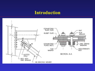
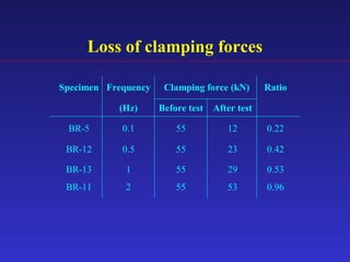
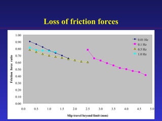
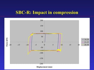
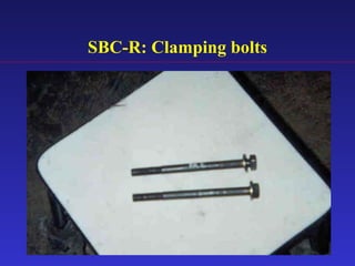
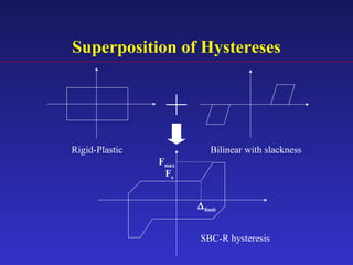
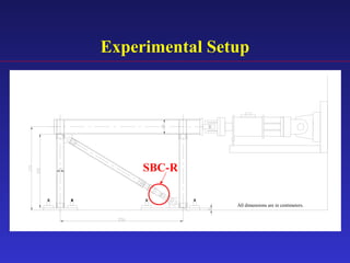
1) The document proposes an enhanced slotted-bolted connection (SBC-R) to address problems with conventional slotted-bolted friction dampers experiencing loss of friction force when bolts hit the ends of slots during earthquakes.
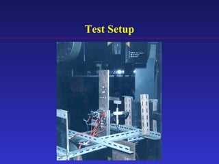
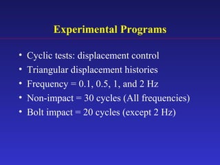
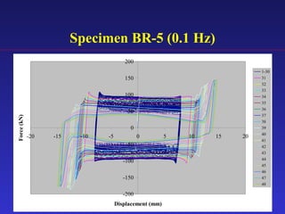
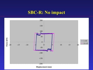
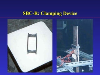
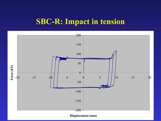
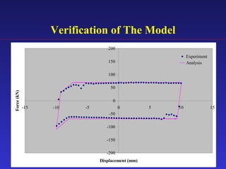
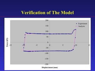
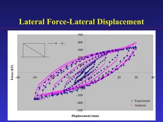
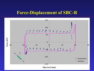
2) Experimental testing showed the SBC-R, which includes restrainers to prevent bolt impacts, maintained stable hysteresis and no loss of friction force under cyclic loading.
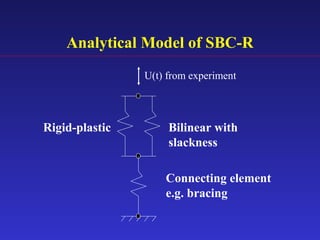
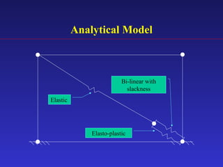
3) An analytical model was developed to model the hysteresis behavior of the SBC-R and was verified against experimental results.