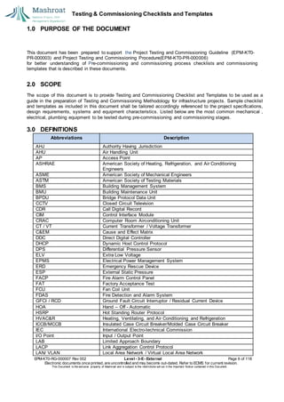
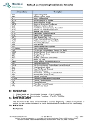
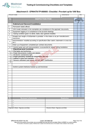
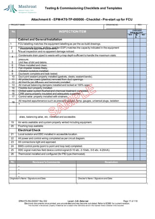
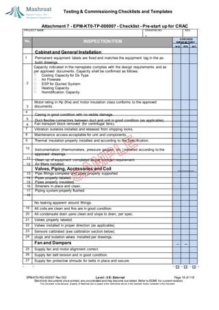
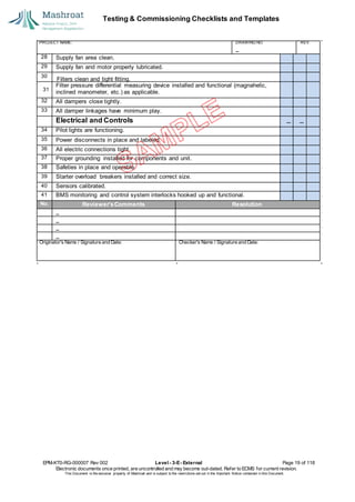
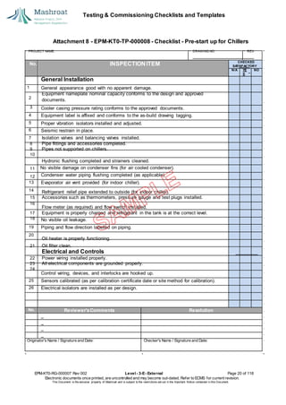
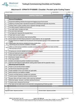
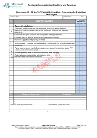
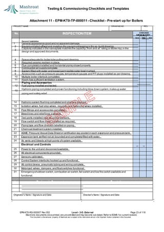
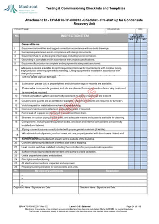
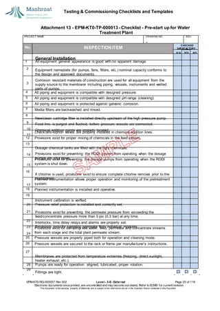
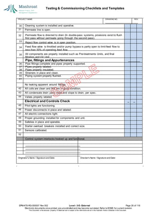
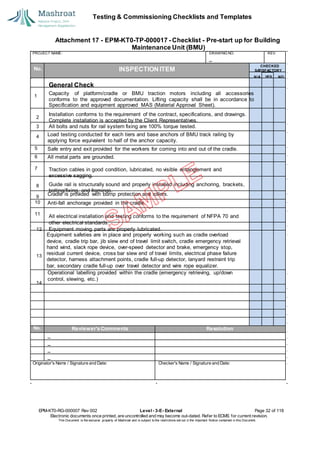
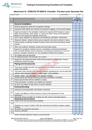
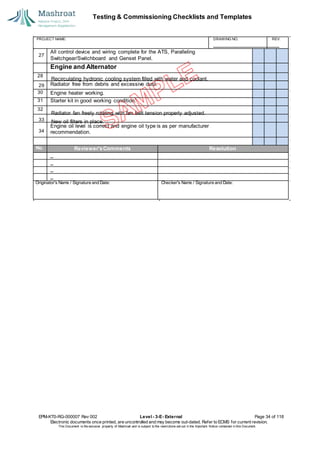
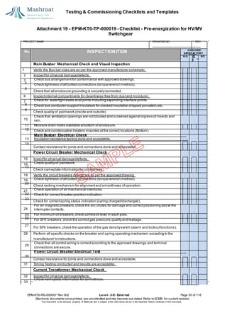
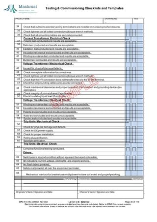
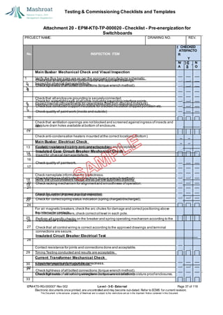
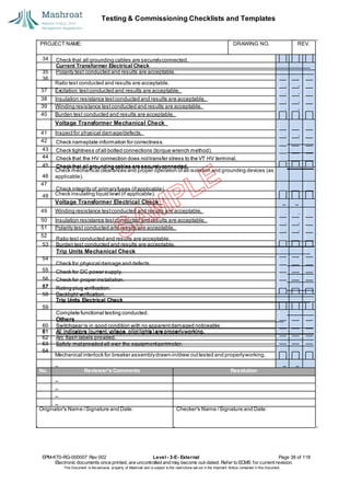
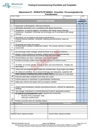
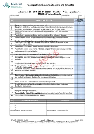
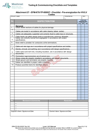
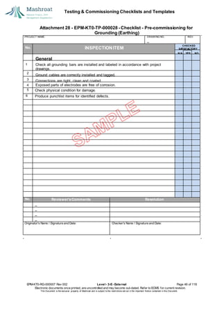
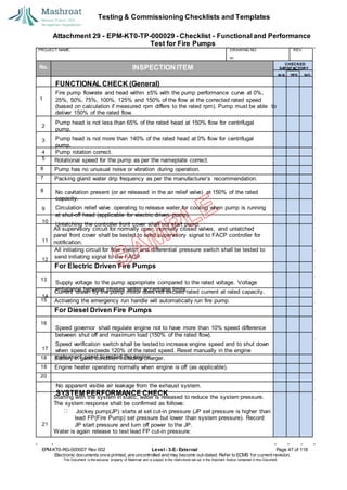
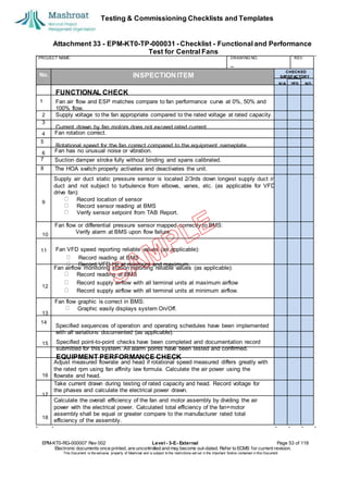
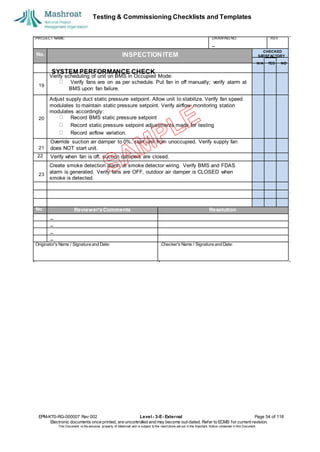
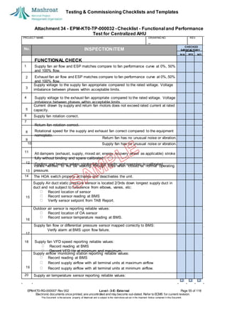
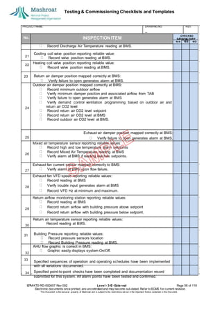
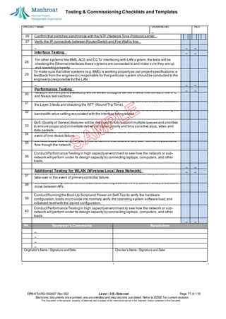
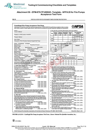
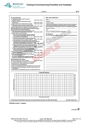
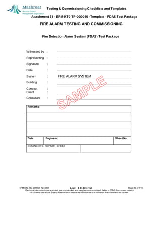
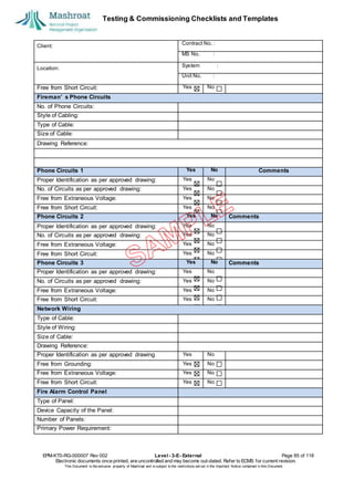
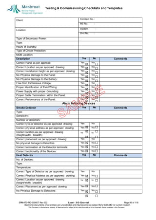
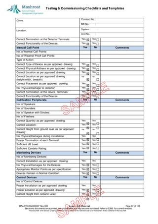
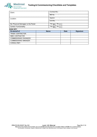
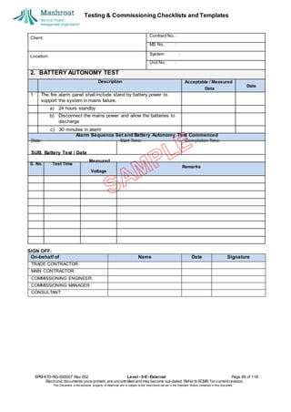
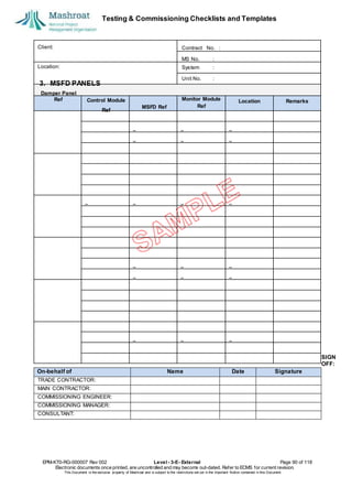
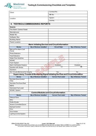
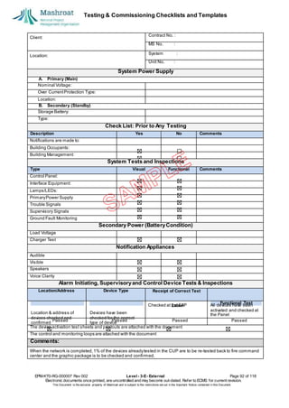
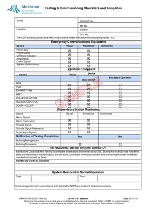
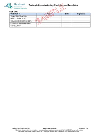
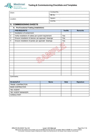
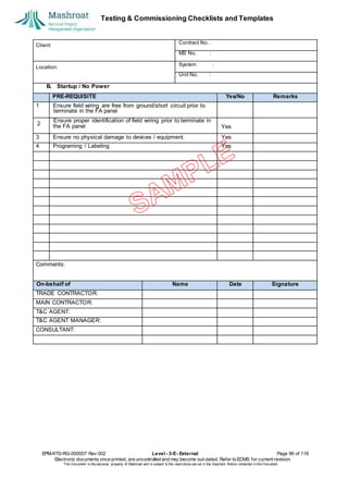
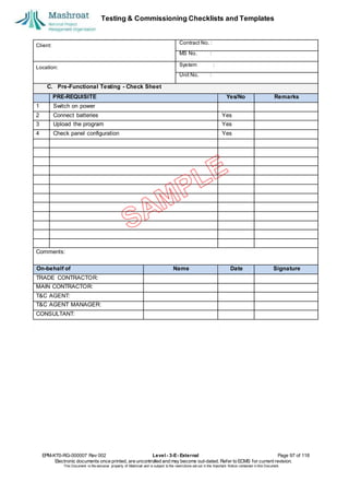
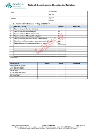
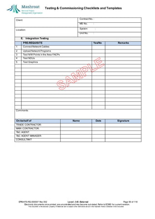
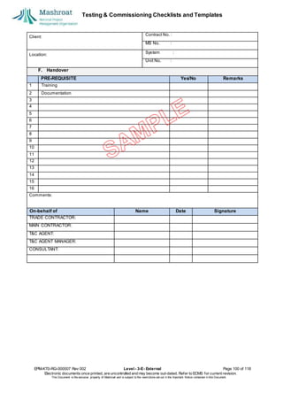
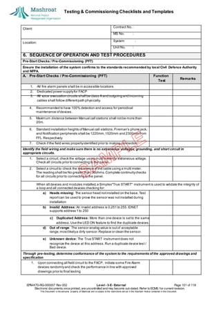
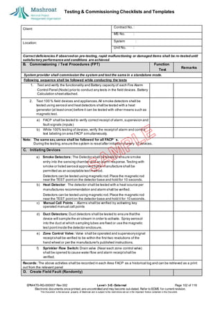
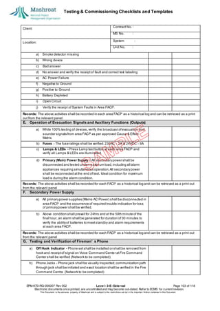
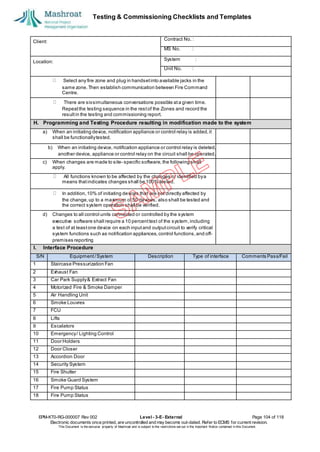
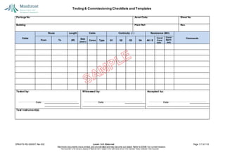
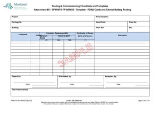
National Project, O&M Management
Organization (Mashroat)
Mashroat Projects White Book
Volume 10, Chapter 3
Testing & Commissioning Checklists and
Templates
DocumentNo. EPM-KT0-RG-000007 Rev002
EPM-KT0-RG-000007 Rev 002 Level - 3-E- External Page 1 of 118
Electronic documents once printed, are uncontrolled and may become out-dated. Refer to ECMS for current revision.
This Document is the ex
clusiv
e property of Mashroat and is subject to the restrictions set out in the Im
portant Notice contained in this Docum
ent.
Testing & Commissioning Checklists and Templates
Document Revisions History:
EPM-KT0-RG-000007 Rev 002 Level - 3-E- External Page 2 of 118
Electronic documents once printed, are uncontrolled and may become out-dated. Refer to ECMS for current revision.
This Document is the ex
clusiv
e property of Mashroat and is subject to the restrictions set out in the Im
portant Notice contained in this Docum
ent.
Revision: Date: Reason For Issue
000 30/10/2017 For Use
001 06/02/2018 For Use
002 25/11/2018 For Use
Testing & Commissioning Checklists and Templates
THIS NOTICE MUST ACCOMPANY EVERY COPY OF THIS DOCUMENT
IMPORTANT NOTICE
This document, (“Document”) is the exclusive property of the National Project,Operation and Maintenance Management
Organization (“Mashroat”).
This Document should be read in its entirety including the terms of this Important Notice. The government entities may
disclose this Document or extracts of this Document to their respective consultants and/or contractors, provided that such
disclosure includes this Important Notice.
Any use or reliance on this Document, or extracts thereof, by any party, including government entities and their respective
consultants and/or contractors,is atthatthird party’s sole risk and responsibility. Mashroat, to the maximum extent permitted
by law, disclaim all liability (including for losses or damages of whatsoever nature claimed on whatsoever basis including
negligence or otherwise) to any third party howsoever arising with respect to or in connection with the use of this Document
including any liability caused by negligent acts or omissions.
This Documentand its contents are valid only for the conditions reported in itand as of the date of this Document.
EPM-KT0-RG-000007 Rev 002 Level - 3-E- External Page 3 of 118
Electronic documents once printed, are uncontrolled and may become out-dated. Refer to ECMS for current revision.
This Document is the ex
clusiv
e property of Mashroat and is subject to the restrictions set out in the Im
portant Notice contained in this Docum
ent.
Testing & Commissioning Checklists and Templates
Table of Contents
1.0 PURPOSE OF THE DOCUMENT ................................................................................................... 6
2.0 SCOPE ........................................................................................................................................... 6
3.0 DEFINITIONS ................................................................................................................................. 6
4.0 REFERENCES ............................................................................................................................... 7
5.0 RESPONSIBILITIES ...................................................................................................................... 7
6.0 PROCESS ...................................................................................................................................... 7
7.0 ATTACHMENTS ............................................................................................................................ 8
T&C CHECKLIST AND TEMPLATES ...................................................................................................... 8
Attachment 1 - EPM-KT0-TP-000001 - Checklist - Pre-start up for Pumps ..............................................10
Attachment 2 - EPM-KT0-TP-000002 - Checklist - Pre-start up for Fire Pumps .......................................11
Attachment 3 - EPM-KT0-TP-000003 - Checklist - Pre-start up for Fans..................................................13
Attachment 4 - EPM-KT0-TP-000004 - Checklist - Pre-start up for Centralized AHU ...............................14
Attachment 5 - EPM-KT0-TP-000005 - Checklist - Pre-start up for VAV Box ...........................................16
Attachment 6 - EPM-KT0-TP-000006 - Checklist - Pre-start up for FCU ..................................................17
Attachment 7 - EPM-KT0-TP-000007 - Checklist - Pre-start up for CRAC ...............................................18
Attachment 8 - EPM-KT0-TP-000008 - Checklist - Pre-start up for Chillers ..............................................20
Attachment 9 - EPM-KT0-TP-000009 - Checklist - Pre-start up for Cooling Towers .................................21
Attachment 10 - EPM-KT0-TP-000010 - Checklist - Pre-start up for Plate Heat Exchangers ...................22
Attachment 11 - EPM-KT0-TP-000011 - Checklist - Pre-start up for Boilers .............................................23
Attachment 12 - EPM-KT0-TP-000012 - Checklist - Pre-start up for Condensate Recovery Unit .............24
Attachment 13 - EPM-KT0-TP-000013 - Checklist - Pre-start up for Water Treatment Plant ....................25
Attachment 14 - EPM-KT0-TP-000014 - Checklist - Pre-start up for Waste Water Treatment Plant .........27
Attachment 15 - EPM-KT0-TP-000015 - Checklist - Pre-start up for Electric Traction Elevator ................29
Attachment 16 - EPM-KT0-TP-000016 - Checklist - Pre-start up for Escalator and Moving Walks ...........31
Attachment 17 - EPM-KT0-TP-000017 - Checklist - Pre-start up for Building Maintenance Unit (BMU) ...32
Attachment 18 - EPM-KT0-TP-000018 - Checklist - Pre-start up for Generator Set .................................33
Attachment 19 - EPM-KT0-TP-000019 - Checklist - Pre-energization for HV/MV Switchgear ..................35
Attachment 20 - EPM-KT0-TP-000020 - Checklist - Pre-energization for Switchboards ...........................37
Attachment 21 - EPM-KT0-TP-000021 - Checklist - Pre-energization for Transformers ...........................39
Attachment 22 - EPM-KT0-TP-000022 - Checklist - Pre-commissioning for HV/MV Ring Main Unit .........40
Attachment 23 - EPM-KT0-TP-000023 - Checklist - Pre-commissioning for HV/MV Capacitor Banks ......41
Attachment 24 - EPM-KT0-TP-000024 - Checklist - Pre-energization for MV/LV Automatic Transfer
Switch............................................................................................................................................42
Attachment 25 - EPM-KT0-TP-000025 - Checklist - Pre-energization for UPS .........................................43
Attachment 26 - EPM-KT0-TP-000026 - Checklist - Pre-energization for MCC/Distribution Boards .........44
Attachment 27 - EPM-KT0-TP-000027 - Checklist - Pre-energization for HV/LV Cables ..........................45
Attachment 28 - EPM-KT0-TP-000028 - Checklist - Pre-commissioning for Grounding (Earthing) ...........46
Attachment 29 - EPM-KT0-TP-000029 - Checklist - Functional and Performance Test for Fire Pumps ....47
Attachment 30 - EPM-KT0-TP-000057 - Checklist - Pre-start Up for VoIP ...............................................49
Attachment 31 - EPM-KT0-TP-000059 - Checklist - Pre-start Up for LAN/WLAN .....................................50
Attachment 32 - EPM-KT0-TP-000030 - Checklist - Functional and Performance Test for Chilled
Water Pumps.................................................................................................................................51
Attachment 33 - EPM-KT0-TP-000031 - Checklist - Functional and Performance Test for Central Fans..53
Attachment 34 - EPM-KT0-TP-000032 - Checklist - Functional and Performance Test for Centralized
AHU...............................................................................................................................................55
Attachment 35 - EPM-KT0-TP-000033 - Checklist - Functional and Performance Test for CRAC
(Precision Unit) ..............................................................................................................................59
Attachment 36 - EPM-KT0-TP-000034 - Checklist - Functional and Performance Test for FCU...............61
Attachment 37 - EPM-KT0-TP-000035 - Checklist - Functional and Performance Test for Cross Flow
Cooling Towers ..............................................................................................................................62
Attachment 38 - EPM-KT0-TP-000036 - Checklist - Functional and Performance Test for Boilers ...........63
Attachment 39 - EPM-KT0-TP-000037 - Checklist - Functional and Performance Test for Water
Treatment Plant .............................................................................................................................65
Attachment 40 - EPM-KT0-TP-000038 - Checklist - Functional and Performance Test for Waste Water
Treatment Plant .............................................................................................................................67
EPM-KT0-RG-000007 Rev 002 Level - 3-E- External Page 4 of 118
Electronic documents once printed, are uncontrolled and may become out-dated. Refer to ECMS for current revision.
This Document is the ex
clusiv
e property of Mashroat and is subject to the restrictions set out in the Im
portant Notice contained in this Docum
ent.
Testing & Commissioning Checklists and Templates
Attachment 41 - EPM-KT0-TP-000039 - Checklist - Functional and Performance Test for Condensate
Recovery Unit ................................................................................................................................68
Attachment 42 - EPM-KT0-TP-000040 - Checklist - Functional and Performance Test for Electric
Traction Elevators ..........................................................................................................................69
Attachment 43 - EPM-KT0-TP-000041 - Checklist - Functional and Performance Test for Escalators
and Moving Walks .........................................................................................................................70
Attachment 44 - EPM-KT0-TP-000042 - Checklist - Functional and Performance Test for Building
Maintenance Unit ...........................................................................................................................71
Attachment 45 - EPM-KT0-TP-000043 - Checklist - Functional and Performance Test for HV/MV
Capacitor Banks ............................................................................................................................72
Attachment 46 - EPM-KT0-TP-000044 - Checklist - Functional and Performance Test for UPS...............73
Attachment 47 - EPM-KT0-TP-000056 - Checklist - Functional and Performance Test for Pressure
Independent VAV....................................................................................................................... ....74
Attachment 48 - EPM-KT0-TP-000058 - Checklist - Functional and Performance Test for VoIP ..............75
Attachment 49 - EPM-KT0-TP-000060 - Checklist - Functional and Performance Test for LAN/WLAN....76
Attachment 50 - EPM-KT0-TP-000045 - Template - NFPA 20 for Fire Pumps Acceptance Test Form .....78
Attachment 51 - EPM-KT0-TP-000046 - Template - FDAS Test Package................................................80
Attachment 52 - EPM-KT0-TP-000047 - Template - Earth Electrode Testing.........................................108
Attachment 53 - EPM-KT0-TP-000048 - Template - Door Intercom Testing...........................................109
Attachment 54 - EPM-KT0-TP-000049 - Template - Car Park Access System Testing ..........................110
Attachment 55 - EPM-KT0-TP-000050 - Template - Security and Access Control Testing.....................111
Attachment 56 - EPM-KT0-TP-000051 - Template - BMS Graphics Testing ..........................................113
Attachment 57 - EPM-KT0-TP-000052 - Template - BMS Control Set-point and Parameter Testing ......114
Attachment 58 - EPM-KT0-TP-000053 - Template - BMS and EPMS PTP and Loop Testing ................115
Attachment 59 - EPM-KT0-TP-000054 - Template - Cable Testing........................................................116
Attachment 60 - EPM-KT0-TP-000055 - Template - FDAS Cable and Central Battery Testing ..............118
EPM-KT0-RG-000007 Rev 002 Level - 3-E- External Page 5 of 118
Electronic documents once printed, are uncontrolled and may become out-dated. Refer to ECMS for current revision.
This Document is the ex
clusiv
e property of Mashroat and is subject to the restrictions set out in the Im
portant Notice contained in this Docum
ent.
Testing & Commissioning Checklists and Templates
1.0 PURPOSE OF THE DOCUMENT
This document has been prepared to support the Project Testing and Commissioning Guideline (EPM-KT0-
PR-000003) and Project Testing and Commissioning Procedure(EPM-KT0-PR-000006)
for better understanding of Pre-commissioning and commissioning process checklists and commissioning
templates that is described in these documents.
2.0 SCOPE
The scope of this document is to provide Testing and Commissioning Checklist and Templates to be used as a
guide in the preparation of Testing and Commissioning Methodology for infrastructure projects. Sample checklist
and templates as included in this document shall be tailored accordingly referenced to the project specifications,
design requirements, systems and equipment characteristics. Listed below are the most common mechanical ,
electrical, plumbing equipment to be tested during pre-commissioning and commissioning stages.
3.0 DEFINITIONS
EPM-KT0-RG-000007 Rev 002 Level - 3-E- External Page 6 of 118
Electronic documents once printed, are uncontrolled and may become out-dated. Refer to ECMS for current revision.
This Document is the ex
clusiv
e property of Mashroat and is subject to the restrictions set out in the Im
portant Notice contained in this Docum
ent.
Abbreviations Description
AHJ Authority Having Jurisdiction
AHU Air Handling Unit
AP Access Point
ASHRAE American Society of Heating, Refrigeration, and Air Conditioning
Engineers
ASME American Society of Mechanical Engineers
ASTM American Society of Testing Materials
BMS Building Management System
BMU Building Maintenance Unit
BPDU Bridge Protocol Data Unit
CCTV Closed Circuit Television
CDR Call Digital Record
CIM Control Interface Module
CRAC Computer Room Airconditioning Unit
CT / VT Current Transformer / Voltage Transformer
C&EM Cause and Effect Matrix
DDC Direct Digital Controller
DHCP Dynamic Host Control Protocol
DPS Differential Pressure Sensor
ELV Extra Low Voltage
EPMS Electrical Power Management System
ERD Emergency Rescue Device
ESP External Static Pressure
FACP Fire Alarm Control Panel
FAT Factory Acceptance Test
FCU Fan Coil Unit
FDAS Fire Detection and Alarm System
GFCI / RCD Ground Fault Circuit Interruptor / Residual Current Device
HOA Hand – Off - Automatic
HSRP Hot Standing Router Protocol
HVAC&R Heating, Ventilating, and Air Conditioning and Refrigeration
ICCB/MCCB Insulated Case Circuit Breaker/Molded Case Circuit Breaker
IEC International Electro-technical Commission
I/O Point Input / Output Point
LAB Limited Approach Boundary
LACP Link Aggregation Control Protocol
LAN/ VLAN Local Area Network / Virtual Local Area Network
Testing & Commissioning Checklists and Templates
4.0 REFERENCES
1. Project Testing and Commissioning Guideline - EPM-KT0-000003
2. Project Testing and Commissioning Procedure – EPM-KT0-PR-000006
5.0 RESPONSIBILITIES
This document will be owned and maintained by Mashroat Engineering. Entities are responsible to
provide this checklist and templates to all parties responsible for the preparation of T&C Methodology.
6.0 PROCESS
Not Applicable
EPM-KT0-RG-000007 Rev 002 Level - 3-E- External Page 7 of 118
Electronic documents once printed, are uncontrolled and may become out-dated. Refer to ECMS for current revision.
This Document is the ex
clusiv
e property of Mashroat and is subject to the restrictions set out in the Im
portant Notice contained in this Docum
ent.
Abbreviations Description
LED Light Emitting Diode
MAS Material Approval Sheet
MCC Motor Control Center
MCCB Molded Case Circuit Breaker
MIM Monitor Interface Module
MSFD Motorized Smoke and Fire Damper
NAC Notification Appliance Circuit
NETA interNational Electrical Testing Association
NFPA National Fire Protection Association
NTP Network Time Protocol
OCPD Over Current Protective Device
OPR Owner Project Requirement
OSPF Open Shortest Path First
PABX Private Automatic Branch Exchange
PAVA Public Annunciation and Voice Alarm
PCB Power Circuit Breaker
PoW Point of Wave
PPE Personal Protective Equipment
PTP Testing Point to Point Testing
P&ID Process and Instrumentation Diagram (for BMS)
RCBO Residual Current Circuit Breaker with Overload
RCD Residual Current Device
RMU Ring Main Unit
RODI Reverse Osmosis De-ionize Water
RTT Round Trip Time
SNMP Simple Network Management Protocol
TAB Testing and Balancing
TCP/IP Tele Communications Protocol over Internet Protocol
TDS Total Dissoloved Solids
TFTP Trivial File Transfer Protocol
TSP Total Static Pressure
UL/FM Underwriters Laboratory / Factory Mutual
UPS Uninterruptible Power Supply
VAV Variable Air Volume
VESDA Very Early Smoke Detection Appliance
VFD Variable Frequency Drive
VG Voltage Gateways
VoIP Voice Over Internet Protocol
VPC Virtual Private Cloud
Testing & Commissioning Checklists and Templates
7.0 ATTACHMENTS
T&C CHECKLIST AND TEMPLATES
1. EPM-KT0-TP-000001 - Checklist - Pre-start up for Pumps
2. EPM-KT0-TP-000002 - Checklist - Pre-start up for Fire Pumps
3. EPM-KT0-TP-000003 - Checklist - Pre-start up for Fans
4. EPM-KT0-TP-000004 - Checklist - Pre-start up for Centralized AHU
5. EPM-KT0-TP-000005 - Checklist - Pre-start up for VAV Box
6. EPM-KT0-TP-000006 - Checklist - Pre-start up for FCU
7. EPM-KT0-TP-000007 - Checklist - Pre-start up for CRAC
8. EPM-KT0-TP-000008 - Checklist - Pre-start up for Chillers
9. EPM-KT0-TP-000009 - Checklist - Pre-start up for Cooling Towers
10. EPM-KT0-TP-000010 - Checklist - Pre-start up for Plate Heat Exchangers
11. EPM-KT0-TP-000011 - Checklist - Pre-start up for Boilers
12. EPM-KT0-TP-000012 - Checklist - Pre-start up for Condensate Recovery Unit
13. EPM-KT0-TP-000013 - Checklist - Pre-start up for Water Treatment Plant
14. EPM-KT0-TP-000014 - Checklist - Pre-start up for Waste Water Treatment Plant
15. EPM-KT0-TP-000015 - Checklist - Pre-start up for Electric Traction Elevator
16. EPM-KT0-TP-000016 - Checklist - Pre-start up for Escalator and Moving Walks
17. EPM-KT0-TP-000017 - Checklist - Pre-start up for Building Maintenance Unit (BMU)
18. EPM-KT0-TP-000018 - Checklist - Pre-start up for Generator Set
19. EPM-KT0-TP-000019 - Checklist - Pre-energization for HV/MV Switchgear
20. EPM-KT0-TP-000020 - Checklist - Pre-energization for Switchboards
21. EPM-KT0-TP-000021 - Checklist - Pre-energization for Transformers
22. EPM-KT0-TP-000022 - Checklist - Pre-commissioning for HV/MV Ring Main Unit
23. EPM-KT0-TP-000023 - Checklist - Pre-commissioning for HV/MV Capacitor Banks
24. EPM-KT0-TP-000024 - Checklist - Pre-energization for MV/LV Automatic Transfer Switch
25. EPM-KT0-TP-000025 - Checklist - Pre-energization for UPS
26. EPM-KT0-TP-000026 - Checklist - Pre-energization for MCC/Distribution Boards
27. EPM-KT0-TP-000027 - Checklist - Pre-energization for HV/LV Cables
28. EPM-KT0-TP-000028 - Checklist - Pre-commissioning for Grounding (Earthing)
29. EPM-KT0-TP-000029 - Checklist - Functional and Performance Test for Fire Pumps
30. EPM-KT0-TP-000030 - Checklist - Functional and Performance Test for Chilled Water Pumps
31. EPM-KT0-TP-000031 - Checklist - Functional and Performance Test for Central Fans
32. EPM-KT0-TP-000032 - Checklist - Functional and Performance Test for Centralized AHU
33. EPM-KT0-TP-000033 - Checklist - Functional and Performance Test for CRAC (Precision Unit)
34. EPM-KT0-TP-000034 - Checklist - Functional and Performance Test for FCU
35. EPM-KT0-TP-000035 - Checklist - Functional and Performance Test for Cross Flow Cooling Towers
36. EPM-KT0-TP-000036 - Checklist - Functional and Performance Test for Boilers
37. EPM-KT0-TP-000037 - Checklist - Functional and Performance Test for Water Treatment Plant
38. EPM-KT0-TP-000038 - Checklist - Functional and Performance Test for Waste Water Treatment Plant
39. EPM-KT0-TP-000039 - Checklist - Functional and Performance Test for Condensate Recovery Unit
40. EPM-KT0-TP-000040 - Checklist - Functional and Performance Test for Electric Traction Elevators
41. EPM-KT0-TP-000041 - Checklist - Functional and Performance Test for Escalators and Moving Walks
42. EPM-KT0-TP-000042 - Checklist - Functional and Performance Test for Building Maintenance Unit
43. EPM-KT0-TP-000043 - Checklist - Functional and Performance Test for HV/MV Capacitor Banks
44. EPM-KT0-TP-000044 - Checklist - Functional and Performance Test for UPS
45. EPM-KT0-TP-000056 - Checklist - Functional and Performance Test for Pressure Independent VAV
46. EPM-KT0-TP-000045 - Template - NFPA 20 for Fire Pumps Acceptance Test Fom
47. EPM-KT0-TP-000046 - Template - FDAS Test Package
48. EPM-KT0-TP-000047 - Template - Earth Electrode Testing
49. EPM-KT0-TP-000048 - Template - Door Intercom Testing
50. EPM-KT0-TP-000049 - Template - Car Park Access System Testing
51. EPM-KT0-TP-000050 - Template - Security and Access Control Testing
52. EPM-KT0-TP-000051 - Template - BMS Graphics Testing
53. EPM-KT0-TP-000052 - Template - BMS Control Set-point and Parameter Testing
54. EPM-KT0-TP-000053 - Template - BMS and EPMS PTP and Loop Testing
55. EPM-KT0-TP-000054 - Template - Cable Testing
56. EPM-KT0-TP-000055 - Template - FDAS Cable and Battery Autonomy Testing
EPM-KT0-RG-000007 Rev 002 Level - 3-E- External Page 8 of 118
Electronic documents once printed, are uncontrolled and may become out-dated. Refer to ECMS for current revision.
This Document is the ex
clusiv
e property of Mashroat and is subject to the restrictions set out in the Im
portant Notice contained in this Docum
ent.
Testing & Commissioning Checklists and Templates
57. EPM-KT0-TP-000057 - Checklist - Pre-start Up for VoIP
58.EPM-KT0-TP-000058 - Checklist - Functional and Performance Test for VoIP
59.EPM-KT0-TP-000059 - Checklist - Pre-start Up for LAN/WLAN
60.EPM-KT0-TP-000060 - Checklist - Functional and Performance Test for LAN/WLAN
EPM-KT0-RG-000007 Rev 002 Level - 3-E- External Page 9 of 118
Electronic documents once printed, are uncontrolled and may become out-dated. Refer to ECMS for current revision.
This Document is the ex
clusiv
e property of Mashroat and is subject to the restrictions set out in the Im
portant Notice contained in this Docum
ent.
Testing & Commissioning Checklists and Templates
Attachment 1 - EPM-KT0-TP-000001 - Checklist - Pre-start up for Pumps
EPM-KT0-RG-000007 Rev 002 Level - 3-E- External Page 10 of 118
Electronic documents once printed, are uncontrolled and may become out-dated. Refer to ECMS for current revision.
This Document is the ex
clusiv
e property of Mashroat and is subject to the restrictions set out in the Im
portant Notice contained in this Docum
ent.
PROJECT NAME: DRAWING NO. REV.
No. INSPECTION ITEM
Equipment is de-energized, safe and locked-out.
Equipment is identified and tagged correctly in accordance with as-build drawings.
3 Nameplate parameters are in compliance with design documents.
4
Grounding is complete and in accordance withproject specifications.
6 Pump foundations are complete and equipment is adequately anchored.
7
Adequate space is available to permit equipment removal for maintenance with minimal
piping, tray/conduit or other equipment dismantling. Lifting equipment is installed in
accordance with design documents.
Auxiliary systems (i.e. lube oil, purge, quench, balance, cooling, seal, etc.) are properly
installed with no visible signs of damage.
urnover).
14 Visibly inspect for installation mechanical seals/packing.
15 Drains and vents are installed and adequately routed, if required.
16 Pump leak off is piped or channeled to convenient floor drain.
17
Vibration panels are properly installed and internals are clean and free of debris or rust.
Internal components are securely mountedand labeled in accordance with project
specifications.
orrectly installedand labeled.
21 Piping connections are correctly bolted with proper gasket materials (if visible).
22
etc.
24 Produce punchlist items for identified defects.
No. Reviewer'sComments Resolution
Originator's Name / Signature and Date: Checker's Name / Signature and Date:
CHECKED
SA
TISFACTORY
N/A YES NO
1
2
Equipment has no visible signs of damage, includingrust or corrosion.
5
Grouting is complete.
8
9
Lubrication grease (oil) is properly filled and lubricationtags or records are available.
11
Preservative compounds, greases, and oils are cleaned from equipment surfaces. Any
10
desiccant is removed as required.
12 Forced lubrication systems are correctly piped and no leaks or openings are evident.
13
t
Coupling and guards are assembled or available. (Alignment records are required for
Strainers in suction piping are installed; and adequate means and space is available for
cleaning.
18 Vibration instruments/probes are correctly mounted and undamaged.
19
20 c
Components, including control/junction boxes, are clean and internal components are
All cabinets/control panels, junction boxes, etc. are properly sealed with door/covers closed
and properly bolted.
23
Piping appurtenances installed such as pressure gauges, universal test plugs, thermowell,
Testing & Commissioning Checklists and Templates
EPM-KT0-RG-000007 Rev 002 Level - 3-E- External Page 11 of 118
Electronic documents once printed, are uncontrolled and may become out-dated. Refer to ECMS for current revision.
This Document is the ex
clusiv
e property of Mashroat and is subject to the restrictions set out in the Im
portant Notice contained in this Docum
ent.
CHECKED
SA
TISFACTORY
N/A YE
S
NO
General Items
1 General Items
2
Equipment is identified and tagged correctly in accordance with as-build drawings.
4 Nameplate parameters are in compliance with design documents.
5
Grounding is complete and in accordance withproject specifications.
7 Pump foundations are complete and equipment is adequately anchored.
8
Adequate space is available to permit equipment removal for maintenance with minimal
piping, tray/conduit or other equipment dismantling. Lifting equipment is installed in
accordance with design documents.
Auxiliary systems (i.e., lube oil, purge, quench, balance, cooling, seal, etc.) are properly
installed with no visible signs of damage.
urnover).
15 Visibly inspect for installation mechanical seals/packing.
16 Drains and vents are installed and adequately routed, if required.
17 Pump leak off is piped or channeled to convenient floor drain.
18
Vibration panels are properly installed and internals are clean and free of debris or rust.
Internal components are securely mountedand labeled in accordance with project
specifications.
orrectly installedand labeled.
22 Piping connections are correctly bolted with proper gasket materials (if visible).
23
Sensing line completed and installed in-between the fire main line isolation and check valve
with two (2) reverse check valve with 2.4 mm. hole spaced at 5ft. apart as specified by
NFPA 20.
Attachment 2 - EPM-KT0-TP-000002 - Checklist - Pre-start up for Fire Pumps
PROJECT NAME: DRAWING NO. REV.
No. INSPECTION ITEM
Equipment is de-energized, safe and locked-out.
3
Equipment has no visible signs of damage, includingrust or corrosion.
6
Grouting is complete.
9
10
Lubrication grease (oil) is properly filled and lubricationtags or records are available.
12
Preservative compounds, greases, and oils are cleaned from equipment surfaces. Any
11
desiccant is removed as required.
13 Forced lubrication systems are correctly piped and no leaks or openings are evident.
14
t
Coupling and guards are assembled or available. (Alignment records are required for
Strainers in suction piping are installed; and adequate means and space is available for
cleaning.
19 Vibration instruments/probes are correctly mounted and undamaged.
20
21
c
Components, including control/junction boxes, are clean and internal components are
All cabinets/control panels, junction boxes, etc. are properly sealed with door/covers closed
and properly bolted.
24
Test manifold available with UL/FM flowmeter and gauge. Straight pipe lengths downstream
and upstream of the flowmeter comply to the requirement of the flowmeter.
25
Testing & Commissioning Checklists and Templates
EPM-KT0-RG-000007 Rev 002 Level - 3-E- External Page 12 of 118
Electronic documents once printed, are uncontrolled and may become out-dated. Refer to ECMS for current revision.
This Document is the ex
clusiv
e property of Mashroat and is subject to the restrictions set out in the Im
portant Notice contained in this Docum
ent.
PROJECT NAME: DRAWING NO. REV.
26 Main relief line and relief valve installed as required by the design (as applicable).
27
Eccentric reducer provided in the suction of the pump.
29 Produce punchlist items for identified defects.
For Electric Fire Pump
30
f
Circuit breaker for lock rotor overcurrent protectionshall be 300% of the rated load current
All electrical connections inspected and approved.
33 Proper grounding installed for components and units.
For Diesel Fire Pump
34
Batteries and charger available and in good condition.
No. Reviewer'sComments Resolution
Originator's Name / Signature and Date: Checker's Name / Signature and Date:
All appurtenances such as circulating relief valve, casing air release valve, liquid filled
pressure gauges (compound type in the suction is required) installed.
28
or induction motors.
31 Pilot lights are functioning.
32
Sand trap louver installed in room air intakes and room is properly ventilated.
35 Cooling water connections are available, inspected, and approved.
36 c
Fuel connections completedincluding fuel tanks. Installationof fuel system and
ontainments conforms to standards.
37
Testing & Commissioning Checklists and Templates
EPM-KT0-RG-000007 Rev 002 Level - 3-E- External Page 13 of 118
Electronic documents once printed, are uncontrolled and may become out-dated. Refer to ECMS for current revision.
This Document is the ex
clusiv
e property of Mashroat and is subject to the restrictions set out in the Im
portant Notice contained in this Docum
ent.
CHECKED
SA
TISFACTOR
Y
N/A YE
S
NO
Cabinet and General Installation
1 Permanent labels affixed, including for fans.
2
sensor, etc.).
9 Transport block removed (for centrifugal fans).
10 Clean up of equipment completed per contract documents.
Fans and Dampers
11 Fan and motor alignment correct.
12 Fan belt tension and condition good.
13 Fan protective shrouds for belts in place and secure.
14 Fan and motor properly lubricated.
15
All damper linkages have minimum play.
Electrical and Controls
17 Pilot lights are functioning.
18 Power disconnects in placeand labeled.
19
Smoke detectors in place (as applicable).
Variable FrequencyDrive
26 VFD powered (wired to controlled equipment).
27 VFD interlockedto control system.
28
Static pressure or other controlling sensor calibrated.
30 Drive location not subject to excessive temperatures.
31 Drive location not subject to excessive moisture or dirt.
32 Drive size matches motor size.
33 Internal setting designating the model is correct.
No. Reviewer'sComments Resolution
Originator's Name / Signature and Date: Checker's Name / Signature and Date:
Attachment 3 - EPM-KT0-TP-000003 - Checklist - Pre-start up for Fans
PROJECT NAME: DRAWING NO. REV.
No. INSPECTION ITEM
Air flow capacity and ESP indicated in the fan nameplate are same as the approved document.
3 Motor rating such as Hp (Kw) and insulationclass conforms to the approved document.
4 Equipment tagging is in compliance to theas-build drawings.
5 Casing condition good: no dents, leaks, door gaskets installed.
6 Flexible connection between duct and unit tight and in good condition. 7
Vibration isolation equipment installed & released from shipping locks. 8
Instrumentation installed according to specification (flow switch, differential pressure, pressure
All dampers close tightly.
16
All electric connections tight.
20 Proper grounding installed for components and unit.
21 Safeties in place and operable.
22 Starter overload breakers installed and correct size.
23 Sensors calibrated(see below).
24 Control system interlocks hookedup and functional.
25
Static pressure or other controlling sensorproperly locatedand per drawings and calibrated.
29
Testing & Commissioning Checklists and Templates
EPM-KT0-RG-000007 Rev 002 Level - 3-E- External Page 14 of 118
Electronic documents once printed, are uncontrolled and may become out-dated. Refer to ECMS for current revision.
This Document is the ex
clusiv
e property of Mashroat and is subject to the restrictions set out in the Im
portant Notice contained in this Docum
ent.
CHECKED
SA
TISFACTORY
N/
A
YE
S
NO
Cabinet and General Installation
1 Permanent labels affixed, including for fans.
2
Access doors close tightly - no leaks.
7 Flexible connection between duct and unit tight and in good condition.
8 Vibration isolation equipment installed and released from shipping locks.
9 Maintenance access acceptable for unit and components.
10 Internal sound attenuation installed (as applicable for arrayed fans).
11 Thermal insulation properly installed and according to specification.
12 Instrumentation installed according to specification(thermometers, pressure gages, flow
Arrangement of internal accessories (filters, coil, humidifier, fans, etc.) as per approved
document.
16 Transport blocks removed for centrifugal fans.
Valves, Piping, Accessories and Coils
17 Pipe fittings complete and pipes properly supported.
18 Pipes properly labeled.
19 Pipes properly insulated.
20
All condensate drain pans clean and slope to drain, per spec.
25 Valves properly labeled.
26 Valves installed in proper direction (as applicable).
27 chilled water supply sensors properly located and secure
28
plugs and isolation valves installed per drawings.
Fans and Dampers
30
Attachment 4 - EPM-KT0-TP-000004 - Checklist - Pre-start up for Centralized AHU
PROJECT NAME: DRAWING NO. REV.
No. INSPECTION ITEM
Air flow capacity and ESP indicated in the fan nameplate are same as the equipment
schedule and approved document.
3 Motor rating in Hp (Kw) and insulation class conforms to theapproved document.
4
Equipment tagging is in compliance to the as-build drawings.
5 Casing condition good: no dents, leaks, door gaskets installed.
6
meters, etc.).
13 Clean up of equipment completed per contract documents.
14
c
Filters installedand replacement type and efficiency permanently affixed to housing -
onstruction filters removed.
15
Strainers in place and clean.
21 Piping system properly flushed.
22 No leaking apparent around fittings.
23
All coils are clean and fins are in good condition.
24
Sensors calibrated(see calibrationsection below).
29
Supply fan and motor alignment correct.
31 Supply fan belt tension and conditiongood.
32 Supply fan protective shrouds for belts in place and secure.
Testing & Commissioning Checklists and Templates
EPM-KT0-RG-000007 Rev 002 Level - 3-E- External Page 15 of 118
Electronic documents once printed, are uncontrolled and may become out-dated. Refer to ECMS for current revision.
This Document is the ex
clusiv
e property of Mashroat and is subject to the restrictions set out in the Im
portant Notice contained in this Docum
ent.
PROJECT NAME: DRAWING NO. REV.
33
Supply fan and motor properly lubricated.
35 Return/exhaust fan and motor aligned.
36 Return/exhaust fan belt tensionand condition good.
37 Return/exhaust fan protective shrouds for belts in place and secure.
38 Return/exhaust fan area clean.
39 Return/exhaust fan and motor lube lines installed and lubed.
40 Filters clean and tight fitting.
41 Filter pressure differential measuring device installed and functional (magnahelic,
Smoke and fire dampers installed properly per contract docs (proper location, access
doors, appropriate ratings verified).
43
Low limit freeze stat sensorlocated to deal with stratification and bypass.
Electrical and Controls
46 Pilot lights are functioning.
47 Power disconnects in placeand labeled.
48
Sensors calibrated.
53 Control system interlocks hookedup and functional.
54
All control devices, pneumatic tubing and wiring complete.
Variable FrequencyDrive
56 VFD powered (wired to controlled equipment).
57 VFD interlockedto control system.
58
Static pressure or other controlling sensor calibrated.
60 Drive location not subject to excessive temperatures.
61 Drive location not subject to excessive moisture or dirt.
62 Drive size matches motor size.
63 Internal setting designating the model is correct.
No. Reviewer'sComments Resolution
Originator's Name / Signature and Date: Checker's Name / Signature and Date:
Supply fan area clean.
34
inclined manometer, etc.).
42
All dampers close tightly.
44 All damper linkages have minimum play.
45
All electric connections tight.
49 Proper grounding installed for components and unit.
50
Safeties in place and operable.
51 Starter overload breakers installed and correct size.
52
Smoke detectors in place.
55
Static pressure or other controlling sensorproperly locatedand per drawings and
calibrated.
59
Testing & Commissioning Checklists and Templates
EPM-KT0-RG-000007 Rev 002 Level - 3-E- External Page 16 of 118
Electronic documents once printed, are uncontrolled and may become out-dated. Refer to ECMS for current revision.
This Document is the ex
clusiv
e property of Mashroat and is subject to the restrictions set out in the Im
portant Notice contained in this Docum
ent.
CHECKED
SA
TISFACTORY
N/A YE
S
NO
Cabinet and General Installation
1 Permanent labels affixed.
2 VAV model indicated in the nameplate are compliance to the approved documents.
3 Equipment tagging is in compliance to the as-build drawings.
4
Straight duct length of 3xDiameter is provided in the intake or as per manufacturer’s
instruction.
Instrumentation installed according to specification (flow switch, balometer or cross bar,
etc.)
Clean up of equipment completed per contract documents.
Control system interlocks hooked up and functional.
No. Reviewer'sComments Resolution
Originator's Name / Signature and Date: Checker's Name / Signature and Date:
Attachment 5 - EPM-KT0-TP-000005 - Checklist - Pre-start up for VAV Box
PROJECT NAME: DRAWING NO. REV.
No. INSPECTION ITEM
Casing condition good: no dents, leaks, door gaskets installed.
5
6
7
Control panel and unit instrumentation is accessible for above ceiling installation.
Electrical and Controls
9 Pilot lights are functioning.
10 Power disconnects in place and labeled.
11 All electric connections tight.
12 Proper grounding installed for components and unit.
13 Safeties in place and operable.
14 Sensors calibrated (see below) and with NIST Certification.
15
8
Testing & Commissioning Checklists and Templates
EPM-KT0-RG-000007 Rev 002 Level - 3-E- External Page 17 of 118
Electronic documents once printed, are uncontrolled and may become out-dated. Refer to ECMS for current revision.
This Document is the ex
clusiv
e property of Mashroat and is subject to the restrictions set out in the Im
portant Notice contained in this Docum
ent.
CHECKED
SA
TISFACTORY
N/A YE
S
NO
Cabinet and General Installation
1 FCU labelling matches the equipment labellingas per the as-build drawings.
2
s
FCU capacity (tonner, air flow, and fan ESP) matches the capacity indicated in the equipment
alves, balancing valve, etc. installed and accessible.
19 Air vents available and system properly vented including equipment.
20 Flushing loop available
Electrical Check
21 Local isolator and DDC installed in accessible location.
22 All power and control wiring completed as per circuit diagram.
23 All connections tight and approved.
24 BMS control points (point to point and loop test) completed.
25 DDC signal matches field device control signal (0-10 vdc, 2-10vdc, 0-5 vdv, 4-20mA).
26 Thermostat installed and configured (for PID type thermostat).
No. Reviewer'sComments Resolution
Originator's Name / Signature and Date: Checker's Name / Signature and Date:
Attachment 6 - EPM-KT0-TP-000006 - Checklist - Pre-start up for FCU
PROJECT NAME: DRAWING NO. REV.
No. INSPECTION ITEM
chedule and approved documents.
3 Visual inspection and no apparent damage noticed.
4
Condensate drain piped to waste with p-trap depthsufficient tohandle the maximum static
pressure.
5 Unit free of dirt and debris.
6 Filters installed and clean.
7 Fan impeller rotates freely.
8 Vibration isolators installed.
9 Ductwork completeand leak tested.
10 Duct joint sealant properly installed (gaskets, cleats, sealant bands).
11 All protective covers (plastics) removed from duct openings.
12 All third fix (air diffusers and terminals) installed.
13 All manual balancing dampers installedand locked at 100% open.
14 Flexible duct properly installed.
15 Chilled water system flushedand chemical treatment completed.
16 CHW piping properly insulated and adequately supporter.
17 Control valve properly installed with strainers.
18
v
All required appurtenance such as pressure gauges, temp. gauges, universal plugs, isolation
Testing & Commissioning Checklists and Templates
Attachment 7 - EPM-KT0-TP-000007 - Checklist - Pre-start up for CRAC
EPM-KT0-RG-000007 Rev 002 Level - 3-E- External Page 18 of 118
Electronic documents once printed, are uncontrolled and may become out-dated. Refer to ECMS for current revision.
This Document is the ex
clusiv
e property of Mashroat and is subject to the restrictions set out in the Im
portant Notice contained in this Docum
ent.
PROJECT NAME: DRAWING NO. REV.
No. INSPECTION ITEM
Capacity indicated in the nameplate complies with the design requirements and as
per approved documents. Capacity shall be confirmed as follows:
Cooling Capacity for Dx Type
Air Flowrate
ESP for Ducted System
Heating Capacity
Humidification Capacity
Motor rating in Hp (Kw) and motor insulation class conforms to the approved
documents.
4
Fan transport block removed (for centrifugal fans).
7 Vibration isolators installed and released from shipping locks.
8 Maintenance access acceptable for unit and components.
9 Thermal insulation properly installed and according to the Specification.
10
No leaking apparent around fittings.
19 All coils are clean and fins are in good condition.
20 All condensate drain pans clean and slope to drain, per spec.
21 Valves properly labeled.
22 Valves installed in proper direction (as applicable).
23 Sensors calibrated (see calibration section below).
24 plugs and isolation valves installed per drawings.
Fan and Dampers
25 Supply fan and motor alignment correct.
26 Supply fan belt tension and in good condition.
27 Supply fan protective shrouds for belts in place and secure.
CHECKED
SA
TISFACTORY
N/A YES NO
Cabinet and General Installation
1 Permanent equipment labels are fixed and matches the equipment tag in the as-
build drawings.
2
3
Casing in good condition with no visible damage.
5 Duct flexible connectors between duct and unit in good condition (as applicable).
6
Instrumentation (thermometers, pressure gauges, etc.) installed according to the
approved drawings.
11
Clean up of equipment completed as per contract requirement.
12 Air filters installed.
Valves, Piping, Accessories and Coil
13 Pipe fittings complete and pipes properly supported.
14 Pipes properly labeled.
15 Pipes properly insulated.
16 Strainers in place and clean.
17 Piping system properly flushed.
18
Testing & Commissioning Checklists and Templates
EPM-KT0-RG-000007 Rev 002 Level - 3-E- External Page 19 of 118
Electronic documents once printed, are uncontrolled and may become out-dated. Refer to ECMS for current revision.
This Document is the ex
clusiv
e property of Mashroat and is subject to the restrictions set out in the Im
portant Notice contained in this Docum
ent.
PROJECT NAME: DRAWING NO. REV.
28 Supply fan area clean.
29 Supply fan and motor properly lubricated.
30
Filter pressure differential measuring device installed and functional (magnahelic,
inclined manometer, etc.) as applicable.
32 All dampers close tightly.
33 All damper linkages have minimum play.
Electrical and Controls
34 Pilot lights are functioning.
35 Power disconnects in place and labeled.
36 All electric connections tight.
37 Proper grounding installed for components and unit.
38 Safeties in place and operable.
39 Starter overload breakers installed and correct size.
40 Sensors calibrated.
41 BMS monitoring and control system interlocks hooked up and functional.
No. Reviewer'sComments Resolution
Originator's Name / Signature and Date: Checker's Name / Signature and Date:
Filters clean and tight fitting.
31
Testing & Commissioning Checklists and Templates
EPM-KT0-RG-000007 Rev 002 Level - 3-E- External Page 20 of 118
Electronic documents once printed, are uncontrolled and may become out-dated. Refer to ECMS for current revision.
This Document is the ex
clusiv
e property of Mashroat and is subject to the restrictions set out in the Im
portant Notice contained in this Docum
ent.
CHECKED
SA
TISFACTORY
N/A YE
S
NO
General Installation
1 General appearance good with no apparent damage.
2
Cooler casing pressure rating conforms to the approved documents.
4 Equipment label is affixed and conforms to the as-build drawing tagging.
5 Proper vibration isolators installed and adjusted.
6 Seismic restrain in place.
7
No visible damage on condenser fins (for air cooled condenser).
Condenser water piping flushing completed (as applicable).
13 Evaporator air vent provided (for indoor chiller).
14
No visible oil leakage.
19 Piping and flow direction labelled on piping.
20
Control wiring, devices, and interlocks are hooked up.
25 Sensors calibrated (as per calibration certificate date or site method for calibration).
26 Electrical isolators are installed as per design.
No. Reviewer'sComments Resolution
Originator's Name / Signature and Date: Checker's Name / Signature and Date:
Attachment 8 - EPM-KT0-TP-000008 - Checklist - Pre-start up for Chillers
PROJECT NAME: DRAWING NO. REV.
No. INSPECTION ITEM
Equipment nameplate nominal capacity conforms to the design and approved
documents.
3
Isolation valves and balancing valves installed.
8 Pipe fittings and accessories completed.
9 Pipes not supported on chillers.
10
Hydronic flushing completed and strainers cleaned.
11
12
Refrigerant relief pipe extended to outside (for indoor chiller).
15 Accessories such as thermometers, pressure gauge and test plugs installed.
16
Flow meter (as required) and flow switch installed.
17 Equipment is properly charged and refrigerant in the tank is at the correct level.
18
Oil heater is properly functioning.
Oil filter clean.
Electrical and Controls
22 Power wiring installed properly.
23 All electrical components are grounded properly.
24
21
Testing & Commissioning Checklists and Templates
EPM-KT0-RG-000007 Rev 002 Level - 3-E- External Page 21 of 118
Electronic documents once printed, are uncontrolled and may become out-dated. Refer to ECMS for current revision.
This Document is the ex
clusiv
e property of Mashroat and is subject to the restrictions set out in the Im
portant Notice contained in this Docum
ent.
CHECKED
SA
TISFACTORY
N/A YE
S
NO
General Installation
1 Equipment labelling matches the equipment tagging as per the As-build.
2 Capacity ofcooling tower matches the equipment scheduleand approved documents.
3 Cooling Tower in good condition and no apparent damage noticed.
4 Fan belts properly installed and tensioned.
5 Fan shaft collars installed and tight.
6 Fan and motor lubricated.
7 Fan blade pitch adjusted (for propeller fans).
8 Tower basin access in place.
9 Tower basin sump strainers clean and sump filled.
10 Sump heater and other freeze protection in place (alarms, etc.) as applicable.
11 All appurtenances installed such as pressure and temperature gauges in the condenser water
witches/level sensors.
15 All piping are correctly labelled and valves are properly tagged.
16 Chemical treatment system or plan installed.
17 Water treatment report submitted.
18 Distribution header balanced.
19 Test plug installed.
20 Isolation and balancing valves installed as per drawing.
21 Gear box lubricated (as applicablefor rotating water header with fix speed fan motor).
Electrical and Controls
22 Power to unit and disconnect installed.
23 All electrical components grounded.
24 Power available to the sump heater (as applicable).
25 Motor protection and safeties installed.
26 Sensors and field devices installed and calibrated.
27 Control system interlocks hookedup and functional.
28 Bypass valve and tower isolation valve spanning calibrated.
29 Motorized valves, dampers, and float switches functional.
30 Vibration alarm testedand functional.
31 Test high and low water alarms and automatic closing/opening ofmake-up water.
No. Reviewer'sComments Resolution
Originator's Name / Signature and Date: Checker's Name / Signature and Date:
Attachment 9 - EPM-KT0-TP-000009 - Checklist - Pre-start up for Cooling Towers
PROJECT NAME: DRAWING NO. REV.
No. INSPECTION ITEM
piping.
12 Spray water inlet strainer installed and spray nozzle clean.
13 Pipe fitting and accessories installation complete.
14 s
Make-up water piping installation complete includingfloat valve or motorized valve and float
Testing & Commissioning Checklists and Templates
Attachment 10 - EPM-KT0-TP-000010 - Checklist - Pre-start up for Plate Heat
Exchangers
EPM-KT0-RG-000007 Rev 002 Level - 3-E- External Page 22 of 118
Electronic documents once printed, are uncontrolled and may become out-dated. Refer to ECMS for current revision.
This Document is the ex
clusiv
e property of Mashroat and is subject to the restrictions set out in the Im
portant Notice contained in this Docum
ent.
PROJECT NAME: DRAWING NO. REV.
No. INSPECTION ITEM
Capacity of heat exchanger matches the equipment schedule and approved
documents.
3 Equipment is in good condition and no apparent damage observed.
4 Pipework flushing, venting, and chemical treatment completed.
5 Pipework supported and properly insulated
6
Heat exchanger insulated and cladded.
No. Reviewer'sComments Resolution
Originator's Name / Signature and Date: Checker's Name / Signature and Date:
CHECKED
SA
TISFACTORY
N/A YES NO
General Installation
1 Equipment labelling matches the equipment tagging as per the As-build.
2
Isolation valves, strainers, installed including control valves for multiple-parallel heat
exchanger.
7 Piping appurtenances installed such as pressure gauge, temperature gauge, P/T
sensors, and universal test plugs.
8
Double regulating valve or automatic balancing valve installed.
9
Flushing bypass loop provided with isolation valve.
10
Testing & Commissioning Checklists and Templates
EPM-KT0-RG-000007 Rev 002 Level - 3-E- External Page 23 of 118
Electronic documents once printed, are uncontrolled and may become out-dated. Refer to ECMS for current revision.
This Document is the ex
clusiv
e property of Mashroat and is subject to the restrictions set out in the Im
portant Notice contained in this Docum
ent.
14 Hydronic system flushing completed and strainers cleaned.
15 Isolation valves,fuel stop valves, regulator and balancing valves installed.
16 Pipe fittings and accessories completed.
17 Bleed lines and relieflines available.
18 Test ports installed near all control sensors.
19 Flow switch and flow meter installed as required.
20 Piping type and flow direction labelled on piping.
21 Chemical treatmentsystem installed.
22 ASME Pressure Vessel Data Sheetor certification tag posted in each expansion and pressure tank.
23 Expansion tank verified not air bounded and completelyfilled with water.
24 Air vents and bleeds athigh points ofsystem available.
Electrical and Controls
25 Power to the unitand disconnectavailable.
26 All electrical components grounded.
27 Sensors calibrated.
28 Control System interlocks hooked up and functional.
29 All control device, pneumatic tubing and wiring complete.
30 Motorized valves, dampers,and floatswitches functional.
31 Emergencyshutdown switch, combustion air switch,fail switch and low fire switch available and
functional.
Attachment 11 - EPM-KT0-TP-000011 - Checklist - Pre-start up for Boilers
PROJECT NAME: DRAWING NO. REV.
No. INSPECTION ITEM CHECKED
SA
TISFACTORY
N/A YES NO
General Installation
1 General appearance good and no apparentdamage.
2 Equipmentlabel affixed and matches the equipmenttagging in the as-build drawing.
3
Capacity indicated in the nameplate matches the capacity(“from and at” rating or Boiler Hp) in the
design and approved documents.
4 Space adequate for boiler tube pulling and cleaning.
5 Required seismic restrain in place.
6 Flue completelyinstalled and horizontal piping sloped properly.
7 Combustion air supplycomplete.
8 System filled with water and lowestpermissible water level marked.
9 Accessories such as pressure gauges,temperature gauges and P/Tplugs installed as per drawing.
10 Multiple boiler interlock completed.
11 Room has sufficient ventilation system.
Piping and Accessories
12 Fuel piping installed and tested.
13
Hydronic piping completed and proven functioning including blow down system,make-up water
piping and safety relief.
No. Reviewer'sComments Resolution
Originator's Name / Signature and Date: Checker's Name / Signature and Date:
Testing & Commissioning Checklists and Templates
EPM-KT0-RG-000007 Rev 002 Level - 3-E- External Page 24 of 118
Electronic documents once printed, are uncontrolled and may become out-dated. Refer to ECMS for current revision.
This Document is the ex
clusiv
e property of Mashroat and is subject to the restrictions set out in the Im
portant Notice contained in this Docum
ent.
CHECKED
SA
TISFACTORY
N/A YE
S
NO
General Items
1 Equipmentis identified and tagged correctlyin accordance with as-build drawings.
2 Nameplate parameters are in compliance with design documents.
3 Equipmenthas no visible signs ofdamage,including rustor corrosion.
4 Grounding is complete and in accordance with projectspecifications.
5 Equipmentfoundation is complete and equipmentis adequatelyanchored.
Adequate space is available to permitequipment removal for maintenance with minimal piping,
tray/conduit or other equipmentdismantling. Lifting equipmentis installed in accordance with
design documents.
10 Forced lubrication systems are correctlypiped and no leaks or openings are evident.
11 Coupling and guards are assembled or available. (Alignment records are required for turnover).
12 Visiblyinspectfor installation mechanical seals/packing.
13 Drains and vents are installed and adequatelyrouted,if required.
14 Pump leak off is piped or channeled to convenientfloor drain.
15 Strainers in suction piping are installed;and adequate means and space is available for cleaning.
16 Components,including control/junction boxes,are clean and internal components are correctly
installed and labeled.
19 Condensate tank provided with steam vent to outside of the building.
20 Condensate tank provided with overflow pipe with p-trapping.
21 Level control switches installed including the controllers for pump automatic operation.
22 Sufficienthead is provided between tank and pump to avoid cavitation.
23 Unitis properlyinsulated and cladded.
24 Pilotlights are functioning.
25 All electrical connections inspected and approved.
26 Proper grounding installed for components and units.
No. Reviewer'sComments Resolution
Originator's Name / Signature and Date: Checker's Name / Signature and Date:
Attachment 12 - EPM-KT0-TP-000012 - Checklist - Pre-start up for Condensate
RecoveryUnit
PROJECT NAME: DRAWING NO. REV.
No. INSPECTION ITEM
6
7
Auxiliary systems (i.e.,lube oil, purge,quench,balance,cooling,seal,etc.) are properly installed
with no visible signs ofdamage.
8 Lubrication grease (oil) is properlyfilled and lubrication tags or records are available.
9
Preservative compounds,greases,and oils are cleaned from equipmentsurfaces. Any desiccant
is removed as required.
17 Piping connections are correctlybolted with proper gasketmaterials (ifvisible).
18
All cabinets/control panels,junction boxes,etc.are properlysealed with door/covers closed and
properlybolted.
Testing & Commissioning Checklists and Templates
Attachment 13 - EPM-KT0-TP-000013 - Checklist - Pre-start up for Water
Treatment Plant
EPM-KT0-RG-000007 Rev 002 Level - 3-E- External Page 25 of 118
Electronic documents once printed, are uncontrolled and may become out-dated. Refer to ECMS for current revision.
This Document is the ex
clusiv
e property of Mashroat and is subject to the restrictions set out in the Im
portant Notice contained in this Docum
ent.
PROJECT NAME: DRAWING NO. REV.
No. INSPECTION ITEM
4 All piping and equipment is compatible with designed pressure.
5 All piping and equipment is compatible with designed pH range (cleaning).
6 All piping and equipment is protected against galvanic corrosion.
7 Media filters are backwashed and rinsed.
8
Check/anti-siphon valves are properly installed in chemical addition lines.
12 Provisions exist for proper mixing of chemicals in the feed stream.
13
Provisions exist for preventing the dosage pumps from operating when the RODI
system is shut down.
16
Planned instrumentation allows proper operation and monitoring of the pretreatment
system.
18 Planned instrumentation is installed and operative.
19
Provisions exist for sampling raw water, feed, permeate and concentrate streams
from each stage and the total plant permeate stream.
25 Pressure vessels are properly piped both for operation and cleaning mode.
26 Pressure vessels are secured to the rack or frame per manufacturer’s instructions.
27
CHECKED
SA
TISFACTORY
N/A YES NO
General Installation
1 All equipment general appearance is good with no apparent damage.
2
Equipment nameplate (for pumps, fans, filters, etc.) nominal capacity conforms to
the design and approved documents.
3
Corrosion resistant materials of construction are used for all equipment from the
supply source to the membrane including piping, vessels, instruments and wetted
parts of pumps.
New/clean cartridge filter is installed directly upstream of the high pressure pump.
9
Feed line, is purged and flushed, before pressure vessels are connected.
10 Chemical addition points are properly located.
11
Dosage chemical tanks are filled with the right chemicals.
14 Provisions exist for preventing the RODI system from operating when the dosage
pumps are shut down.
15
If chlorine is used, provisions exist to ensure complete chlorine removal prior to the
membranes.
17
Instrument calibration is verified.
20 Pressure relief protection is installed and correctly set.
21 Provisions exist for preventing the permeate pressure from exceeding the
feed/concentrate pressure more than 5 psi (0.3 bar) at any time.
22
Interlocks, time delay relays and alarms are properly set.
23 Provisions exist for sampling permeate from individual modules.
24
Membranes are protected from temperature extremes (freezing, direct sunlight,
heater exhaust, etc.).
28 Pumps are ready for operation: aligned, lubricated, proper rotation.
29
Fittings are tight.
Testing & Commissioning Checklists and Templates
EPM-KT0-RG-000007 Rev 002 Level - 3-E- External Page 26 of 118
Electronic documents once printed, are uncontrolled and may become out-dated. Refer to ECMS for current revision.
This Document is the ex
clusiv
e property of Mashroat and is subject to the restrictions set out in the Im
portant Notice contained in this Docum
ent.
Cleaning system is installed and operative.
31 Permeate line is open.
32
No leaking apparent around fittings.
42 All coils are clean and fins are in good condition.
43 All condensate drain pans clean and slope to drain, per spec.
44 Valves properly labeled
Electrical and Controls Check
45 Pilot lights are functioning.
46 Power disconnects in place and labeled.
47 All electric connections tight.
48 Proper grounding installed for components and unit.
49 Safeties in place and operable.
50 Starter overload breakers installed and correct size.
51 Sensors calibrated.
52
PROJECT NAME: DRAWING NO. REV.
30
Permeate flow is directed to drain (In double-pass systems, provisions exist to flush
first pass without permeate going through the second pass).
33
Reject flow control valve is in open position.
34 Feed flow valve is throttled and/or pump bypass is partly open to limit feed flow to
less than 50% of operating feed flow.
35 All components are properly installed such as Pre-treatments Units, and final
filtration and UV Unit.
Pipe, fittings and Appurtenances
36 Pipe fittings complete and pipes properly supported.
37 Pipes properly labeled.
38 Pipes properly insulated.
39 Strainers in place and clean.
40 Piping system properly flushed.
41
Control system interlocks hooked up and functional.
No. Reviewer'sComments Resolution
Originator's Name / Signature and Date: Checker's Name / Signature and Date:
Testing & Commissioning Checklists and Templates
Attachment 14 - EPM-KT0-TP-000014 - Checklist - Pre-start up for Waste Water
Treatment Plant
EPM-KT0-RG-000007 Rev 002 Level - 3-E- External Page 27 of 118
Electronic documents once printed, are uncontrolled and may become out-dated. Refer to ECMS for current revision.
This Document is the ex
clusiv
e property of Mashroat and is subject to the restrictions set out in the Im
portant Notice contained in this Docum
ent.
PROJECT NAME: DRAWING NO. REV.
No. INSPECTION ITEM
Top of buried tanks are sufficiently above the finished grade to prevent surface
water from entering the plant.
8 Perimeter fence are provided for safety and prevent vandalism.
9 The plant site should be covered with gravel.
10 A suitable access road to the plant must be provided for adequate maintenance.
11 Skimmers and sludge returns are equipped with proper valving.
12
All tanks are properly marked with label and matching to the approved plans and
as-builds.
17
All water and air piping completed and tested including floats valves, switches, and
meters.
19 All tanks are leak tested including connections.
20
All works for aeration tank, equalization tank, settling chamber, sludge holding tank,
tertiary filters, chlorinator, and effluent dozing tank are completed and accepted.
Pipe, fittings and Appurtenances
22 Pipe fittings complete and pipes properly supported.
23 Pipes properly labeled.
24 Pipes properly insulated.
25 Strainers in place and clean.
26 Piping system properly flushed.
CHECKED
SA
TISFACTORY
N/A YES NO
General Installation
1 Tanks are completely free from mud, sand, gravel, and other debris.
2
Pre-filter are installed to prevent large untreatable objects to enter the waste water
tank.
3 The plant must be installed level with proper beddings or pads.
4 Plant that is installed partially or totally below grade, anchors shall be provide to
avoid floatation.
5 Backfilling should be completed after tanks are set to avoid wall stress and ponding
around the plant.
6
For metal tanks, cathodic protection must be connected prior to back filling.
7
Float in dosing chamber must be set at elevations noted on the approved plans to
ensure proper dosing of the filter.
13 Block voids of filters must be filled with grout and walls sealed inside and outside
with tar.
14
Filter sand is certified as acceptable for placement.
15 Chlorinator/dechlorinator units are installed correctly with the weir properly in place.
16
Individual equipment (fans, pumps, mixer, aerators, etc.) are functional tested and
accepted. Capacity of equipment verified in compliance to the approved documents.
Equipment cycling control tested and functioning.
18
High and low water level alarms provided, tested, and working properly.
21
Testing & Commissioning Checklists and Templates
EPM-KT0-RG-000007 Rev 002 Level - 3-E- External Page 28 of 118
Electronic documents once printed, are uncontrolled and may become out-dated. Refer to ECMS for current revision.
This Document is the ex
clusiv
e property of Mashroat and is subject to the restrictions set out in the Im
portant Notice contained in this Docum
ent.
No leaking apparent around fittings.
28 All coils are clean and fins are in good condition.
29 All condensate drain pans clean and slope to drain, per spec.
30 Valves properly labeled.
Electrical and Controls Check
31 Pilot lights are functioning.
32 Power disconnects in place and labeled.
33 All electric connections tight.
34 Proper grounding installed for components and unit.
35 Safeties in place and operable.
36 Starter overload breakers installed and correct size.
37 Sensors calibrated.
38
PROJECT NAME: DRAWING NO. REV.
27
Control system interlocks hooked up and functional.
No. Reviewer'sComments Resolution
Originator's Name / Signature and Date: Checker's Name / Signature and Date:
Testing & Commissioning Checklists and Templates
Attachment 15 - EPM-KT0-TP-000015 - Checklist - Pre-start up for Electric
Traction Elevator
EPM-KT0-RG-000007 Rev 002 Level - 3-E- External Page 29 of 118
Electronic documents once printed, are uncontrolled and may become out-dated. Refer to ECMS for current revision.
This Document is the ex
clusiv
e property of Mashroat and is subject to the restrictions set out in the Im
portant Notice contained in this Docum
ent.
PROJECT NAME: DRAWING NO. REV.
No. INSPECTION ITEM
Lift Pit Check
3
Dimensions ofthe lift pit (length,width, depth) conforms to the plan and requirements ofthe
elevator system.
6
Counter weightpit buffer provided and in good condition. Oil buffer shall be provided for lift car
with traveling velocity more than 1.5 m/s.
8 Lighting provided in the pit.
9 Pit switch provided to stop the elevator car manuallyfrom the pit.
10 Governor rope tension pulleyhas free movement.
11 Limitswitches rollers have free movement.
12 Trailing cable properlyterminated and in good condition.
13 Power outlet provided with GFCI or RCD.
14 Drain system or sump provide to remove accumulation ofwater.
15 Access ladder provide if depth is more than 915 mm.
Lift Car Check (Internal)
16 Capacity of the lift car is displayed or labelled inside the car.
17 Exhaust blower provided and in working order.
18 Alarm bell provided and operational.
19 Lightpoint provided terminating in socketor holder.
20 Two-way communication handsetprovided.
21 Floor indication displayprovided.
22 Lift car internal condition is acceptable.Free from damage and scratches.
23 Car door condition is satisfactoryand operable.
24 Clearance between car sill and landing sillis notmore than 30mm.in each floor.
Lift Car Check (Top)
25 Maintenance switch provided to manuallydirectcar (up or down).
26 Switch board provided for lighting and power sockets.
27 All metal part shall be earthed.
28 Hoistway lighting provided.
29 Retiring cam do not contact with the lever of gate locks.
30 Guide shoe liners (car and counter weight) in good condition and playing freely.
31 Trailing cable is in good condition with no visible damage.
32 Safety switchprovided to manually stopcar.
33 Car top structure is reinforced with no apparent dentingwhen weight is applied.
CHECKED
SA
TISFACTORY
N/A YES NO
General Check
1 Capacity of traction motors including all ofelevator accessories conforms to the approved
documentation.Lifting capacityshall be in accordance to Specification and equipmentapproved
MAS (Material Approval Sheet)
2
Installation conforms to the requirementofASME A.17 and accepted by the Client
Representatives.
4 Pit is clean and dry.
5
Car pit buffer provided and in good condition. Oil buffer shall be provided for lift car with traveling
velocity more than 1.5 m/s.
7
Counterweightguard screen provided and weights are properlystacked and secured with
isolators.
Testing & Commissioning Checklists and Templates
EPM-KT0-RG-000007 Rev 002 Level - 3-E- External Page 30 of 118
Electronic documents once printed, are uncontrolled and may become out-dated. Refer to ECMS for current revision.
This Document is the ex
clusiv
e property of Mashroat and is subject to the restrictions set out in the Im
portant Notice contained in this Docum
ent.
PROJECT NAME: DRAWING NO. REV.
34 Roller guides in good condition and properlylubricated.
35 Suspension ropes are adequatelyfastened.
36 Secured emergencymanhole provided which can onlybe opened from the car top.
Machine Room Check
37 Machine room shall have door locking arrangementand should be keptlocked.Double door
arrangementshall be provided for access ofequipmentand should be self-closing/latching.
Electrical system provided in compliance to ASME requirements such as phase reversal/failure
protection,MCCB rating, earth leakage protection,earthing conductor size,etc. Electrical system is
accepted including all required electrical testing.
43 All metal part shall be earthed.
44 Break shoe liners are in good condition.
45 Operation gear box in good working condition,lubricated with no visible oil spill.
46 Suspension ropes and traction sheaves in good condition.
47 Limitor directional switches in good working condition.
48 Speed governor in good condition and rotates freely.
49 ERD (Emergencyrescue device) provided in the control panel as required by the contract.
50 Batteries are in good working condition.
Fire protection system provided such as pre-action sprinkler system and smoke detection
interlocked to the electrical power supplies (shuttrip feature) to turn-off prior to sprinkler
discharge.
52 Tracking motor structural supportand fixing is adequate and approved by the structural engineer.
Floor Landing Check
53 De-locking mechanism provided in each floor landings.
54 Landing doors are in good condition & sliding freelywith no excessive force provided.
55 Hall button in good working condition.
56 Floor indicator in good working condition.
57 Fireman’s switch provided in ground floor and secondaryrecall floor.
Hoist way Check
58 Hoistway is clean and tidy. Dustpaintprovided as required.
59 Fascia plates provided below each landing as required
60 Hoistway lighting provided and in good working condition.
61 All metal parts shall be earthed.
62 Traction cables in good condition,no visible entanglement,and excessive sagging.
63 Guide rail is structurallysound and properlyinstalled including tie brackets,spreader brackets,
bolting/fixing, and framings.
38 Machine room shall be provided with adequate cooling and ventilation.
39 Room shall be clean and tidy with sufficientlamination.
40 Break releasing device provided and in good condition.
41 Power outlet provided with GFCI or RCD.
42
42
51
64 Sprinklers provided as per Code and statutory requirements.
65 Suitable some detectors provided atthe top mostlocation of the hoistway.
No. Reviewer'sComments Resolution
Originator's Name / Signature and Date: Checker's Name / Signature and Date:
Testing & Commissioning Checklists and Templates
Attachment 16 - EPM-KT0-TP-000016 - Checklist - Pre-start up for Escalator and
Moving Walks
EPM-KT0-RG-000007 Rev 002 Level - 3-E- External Page 31 of 118
Electronic documents once printed, are uncontrolled and may become out-dated. Refer to ECMS for current revision.
This Document is the ex
clusiv
e property of Mashroat and is subject to the restrictions set out in the Im
portant Notice contained in this Docum
ent.
PROJECT NAME: DRAWING NO. REV.
No. INSPECTION ITEM
Capacity of traction motors including all ofelevator accessories conforms to the approved
documentation.Lifting capacityshall be in accordance to Specification and equipmentapproved
MAS (Material Approval Sheet).
4
Escalators and moving walk material enclosure shall conform to non-combustible or limited-
combustible definition byNFPA 101.
5 Adequate ventilation provided to the driving machine,control system,and truss enclosure spaces.
Construction requirements for the inclination and geometry (balustrades height and material used,
handrails width and height,width and tread for moving walk, etc.) shall comply to the requirements
of ASTM A.17.1 section 7.2 to 7.3.
8 Comb plate and comb step impactdevice or safety switch provided.
9 Entrance and exit zones free from any obstructions and obstacles.
10 No missing fixing screws for entrance and exit covers.
11 Deck barricade and anti-slide device provided for escalator.
12 Step and up thrustsafety device and other safety devices (see functional testchecklistfor escalator
and moving walk) provided for escalator and moving walk.
19 Are the combs atleast6 mm deep meshing into step/beltguides?
20 Are there any signs ofstep misalignment– scraping marks on the sides ofthe guarding?
21 Step clearance between side ofstep and skirtguarding notexceeding 4mm gap.
22 Clearance between step edges (ofconsecutive steps) notexceeding 6 mm gap.
23 Does all the guarding have its locating screws/rivets in place?
24 Is the speed governor installed and in good condition?
25 Electrical power system installed according to NFPA 70 and ASMT A.17 requirements.
No. Reviewer'sComments Resolution
Originator's Name / Signature and Date: Checker's Name / Signature and Date:
CHECKED
SA
TISFACTORY
N/A YES NO
1 The escalator/moving walk installed and inspected in accordance with ASTM A.17.1 Standards.
2 Assemblyis in good condition with no apparentdamages noticeable.
3
6
7
Entrance and egress ends shall have comb plates and tread ways compliance to ASTM A.17.1
section 7.4.
13 Is there adequate access and exit clearance from the end of the handrail?
14 Are the entry and exit points sufficientlyilluminated?
15 Are the caution stickers provided and legible?
16 Is the escalator/moving walk stop switch provided,clearlylabelled,and red in color?
17
Is the escalator/moving walk handrail in good condition? i.e.no sharp edges or other hazards
where fingers can get caughtor pinched.
18
Are all the combs in place? Max. 1 tooth missing in any one comb.Minimum comb teeth width
2.5mm.
Testing & Commissioning Checklists and Templates
Attachment 17 - EPM-KT0-TP-000017 - Checklist - Pre-start up for Building
Maintenance Unit (BMU)
EPM-KT0-RG-000007 Rev 002 Level - 3-E- External Page 32 of 118
Electronic documents once printed, are uncontrolled and may become out-dated. Refer to ECMS for current revision.
This Document is the ex
clusiv
e property of Mashroat and is subject to the restrictions set out in the Im
portant Notice contained in this Docum
ent.
PROJECT NAME: DRAWING NO. REV.
No. INSPECTION ITEM
Load testing conducted for each tiers and base anchors of BMU track railing by
applying force equivalent to half of the anchor capacity.
5 Safe entry and exit provided for the workers for coming into and out of the cradle.
6 All metal parts are grounded.
7
Cradle is provided with bump protection and rollers.
10 Anti-fall anchorage provided in the cradle.
11
Equipment safeties are in place and properly working such as cradle overload
device, cradle trip bar, jib slew end of travel limit switch, cradle emergency retrieval
hand wind, slack rope device, over-speed detector and brake, emergency stop,
residual current device, cross bar slew end of travel limits, electrical phase failure
detector, harness attachment points, cradle full-up detector, lanyard restraint trip
bar, secondary cradle full-up over travel detector and wire rope equalizer.
Operational labelling provided within the cradle (emergency retrieving, up/down
control, slewing, etc.)
No. Reviewer'sComments Resolution
Originator's Name / Signature and Date: Checker's Name / Signature and Date:
CHECKED
SA
TISFACTORY
N/A YES NO
General Check
1
Capacity of platform/cradle or BMU traction motors including all accessories
conforms to the approved documentation. Lifting capacity shall be in accordance to
Specification and equipment approved MAS (Material Approval Sheet).
Installation conforms to the requirement of the contract, specifications, and drawings.
Complete installation is accepted by the Client Representatives.
3 All bolts and nuts for rail system fixing are 100% torque tested.
4
2
Traction cables in good condition, lubricated, no visible entanglement and
excessive sagging.
8 Guide rail is structurally sound and properly installed including anchoring, brackets,
bolting/fixing, and framings.
9
All electrical installation and testing conforms to the requirement of NFPA 70 and
other electrical standards.
12 Equipment moving parts are properly lubricated.
13
14
Testing & Commissioning Checklists and Templates
EPM-KT0-RG-000007 Rev 002 Level - 3-E- External Page 33 of 118
Electronic documents once printed, are uncontrolled and may become out-dated. Refer to ECMS for current revision.
This Document is the ex
clusiv
e property of Mashroat and is subject to the restrictions set out in the Im
portant Notice contained in this Docum
ent.
CHECKED
SA
TISFACTORY
N/
A
YE
S
NO
General Installation
1 General appearance good and no apparent damage.
2 Equipment label affixed and matches the equipment tagging in the as-build drawing.
Capacity indicated in the nameplate matches the capacity (KVA) based on service
power rating (standby, prime power, or continuous power rating) and temperature
derating in the design and approved documents.
Exhaust piping completely installed including silencer and horizontal piping sloped
properly.
7
Equipment completely installed inclusive of paralleling switchgear/switchboard,
ATS, and NGR (Neutral Ground Resistors). All metering accessories (VT and CT),
sensors, actuators, interlocks, etc. are completely installed and accepted.
Equipment has passed the table shake testing (required in healthcare). Factory
Certificates shall be provided.
Piping and Accessories
12
Cooling piping and fittings including accessories installation completed.
16 Piping type and flow direction labelled on piping.
17 Pipes are painted, insulated, and cladded (as required).
18 Air vents and bleeds at high points of system available.
Exhaust Ducting
19 Exhaust air ducting provided with flexible connectors.
20
Attachment 18 - EPM-KT0-TP-000018 - Checklist - Pre-start up for Generator Set
PROJECT NAME: DRAWING NO. REV.
No. INSPECTION ITEM
3
Room space adequate for equipment and paralleling switchgear maintenance.
5
4
Required vibration isolation (inertia pad as required) and seismic restrain in place.
6
Room has sufficient ventilation system and sand traps louvers.
8
9 All metallic parts are grounded.
10 All safety precaution and warnings are in place.
11
Fuel piping installed (transfer and supply/return) and tested inclusive of motorized
valves and controls.
13 Fuel tanks (main and day tank) installed including appurtenances such as level float
witches, level indicators, overflow, control valves, and controllers.
14
Isolation valves, fuel stop valves, and regulator installed.
15
Louvers and effective exhaust opening comply to the requirements of the
equipment.
21 Backdraft damper provided for multiple unit with common discharge plenum.
Electrical and Controls
22 Power to the unit and disconnect available.
23
Batteries are in good condition, filled with electrolyte and battery chargers properly
working.
24 All electrical components grounded.
25 Sensors calibrated.
26
Control System interlocks hooked up and functional.
Testing & Commissioning Checklists and Templates
EPM-KT0-RG-000007 Rev 002 Level - 3-E- External Page 34 of 118
Electronic documents once printed, are uncontrolled and may become out-dated. Refer to ECMS for current revision.
This Document is the ex
clusiv
e property of Mashroat and is subject to the restrictions set out in the Im
portant Notice contained in this Docum
ent.
All control device and wiring complete for the ATS, Paralleling
Switchgear/Switchboard and Genset Panel.
Engine and Alternator
28
Radiator free from debris and excessive dust.
30 Engine heater working.
31 Starter kit in good working condition.
32
Engine oil level is correct and engine oil type is as per manufacturer
recommendation.
No. Reviewer'sComments Resolution
Originator's Name / Signature and Date: Checker's Name / Signature and Date:
PROJECT NAME: DRAWING NO. REV.
27
Recirculating hydronic cooling system filled with water and coolant.
29
Radiator fan freely rotating with fan belt tension properly adjusted.
33 New oil filters in place.
34
Testing & Commissioning Checklists and Templates
EPM-KT0-RG-000007 Rev 002 Level - 3-E- External Page 35 of 118
Electronic documents once printed, are uncontrolled and may become out-dated. Refer to ECMS for current revision.
This Document is the ex
clusiv
e property of Mashroat and is subject to the restrictions set out in the Im
portant Notice contained in this Docum
ent.
CHECKED
SA
TISFACTORY
N/A YE
S
NO
Main Busbar Mechanical Check and Visual Inspection
1 Verify the Bus bar sizes are as per the approved manufacturer schematic
2 Inspectfor physical damage/defects.
3
Check that all enclosure grounding is securelyconnected.
6 Inspectinternal compartments for cleanliness (free from dustand moisture).
7
Check quality of paintwork (inside and outside)
10
Contact resistance for joints and connections done and acceptable.
Power Circuit Breaker Mechanical Check
15 Insectfor physical damage/defects.
16
Check nameplate information for correctness.
18 Verify the circuitbreakers ratings are as per the approved drawing
19
Check racking mechanism for alignmentand smoothness ofoperation.
21
Check for correctspring status indication (spring charged/discharged).
24
For SF6 breakers,check the operation of the gas densityswitch (alarm and lockoutfunctions).
28 Perform all specific checks on the breaker and spring operating mechanism according to the
manufacturer’s instructions.
Contact resistance for joints and connections done and acceptable.
31 Timing Testing conducted and results are acceptable.
Current Transformer Mechanical Check
32 Inspectfor physical damage/defects.
33
Attachment 19 - EPM-KT0-TP-000019 - Checklist - Pre-energization for HV/MV
Switchgear
PROJECT NAME: DRAWING NO. REV.
No. INSPECTION ITEM
Check bus arrangementfor conformance with approved drawings.
4 Check tightness ofall bolted connections (torque wrench method).
5
Check for watertightseals atall joints including expanding interface points.
8 Check bus conductor supportinsulators for cracked insulation chipped porcelain,etc.
9
Check that ventilation openings are notblocked and screened againstingress ofinsects and
rain.
Moisture drain holes available atbottom of enclosure.
12
11
Check anti-condensation heaters mounted atthe correct locations (Bottom)
Main Busbar Electrical Check
13 Insulation resistance testing done and acceptable.
14
Check quality of paintwork.
17
Check tightness ofall bolted connections (torque wrench method).
20
Check operation of all mechanical interlocks.
22 Check for correctbreaker position indication.
23
For air magnetic breakers,check the arc chutes for damage and correctpositioning above the
interrupter contacts.
For minimum oil breakers,check correctoil level in each pole.
26
25
For SF6 breakers,check the correct gas pressure,qualityand leakage.
27
Check that all control wiring is correctaccording to the approved drawings and terminal
connections are secure.
Power Circuit Breaker Electrical Test
30
29
Check nameplate information for correctness.
Testing & Commissioning Checklists and Templates
EPM-KT0-RG-000007 Rev 002 Level - 3-E- External Page 36 of 118
Electronic documents once printed, are uncontrolled and may become out-dated. Refer to ECMS for current revision.
This Document is the ex
clusiv
e property of Mashroat and is subject to the restrictions set out in the Im
portant Notice contained in this Docum
ent.
PROJECT NAME: DRAWING NO. REV.
34
Ratio test conducted and results are acceptable.
39 Excitation testconducted and results are acceptable.
40 Insulation resistance testconducted and results are acceptable.
41 Winding resistance testconducted and results are acceptable.
42 Burden test conducted and results are acceptable.
Voltage Transformer Mechanical Check
43 Inspectfor physical damage/defects.
44
Check that all grounding cables are securelyconnected.
48
Check insulating liquid level (if applicable).
Voltage Transformer Electrical Check
51 Winding resistance testconducted and results are acceptable.
52 Insulation resistance testconducted and results are acceptable.
53 Polarity test conducted and results are acceptable.
54
Complete functional testing conducted.
Others
62 Switchgear is in good condition with no apparentdamaged noticeable.
63 All indicators (current,voltage, pilotlights) are properlyworking.
64 Arc flash labels provided.
65 Safety mat provided all over the equipmentperimeter.
66
Check that outdoor secondarywiring terminations are installed in moisture proofenclosures.
35 Check tightness ofall bolted connections (torque wrench method).
36 Check that all grounding cables are securelyconnected.
Current Transformer Electrical Check
37 Polarity test conducted and results are acceptable.
38
Check nameplate information for correctness.
45 Check tightness ofall bolted connections (torque wrench method).
46 Check that the HV connection does nottransfer stress to the VT HV terminal.
47
Check mechanical clearances and proper operation ofall isolation and grounding devices (as
applicable).
Check integrity of primaryfuses (ifapplicable).
50
49
Ratio test conducted and results are acceptable.
55 Burden test conducted and results are acceptable.
Trip Units Mechanical Check
56
Check for physical damage and defects.
57 Check for DC power supply.
58 Check for proper installation.
59 Rating plug verification.
60 Backlightverification.
Trip Units Electrical Check
61
Mechanical interlock for breaker assemblydrawn-in/draw outtested and properlyworking.
No. Reviewer'sComments Resolution
Originator's Name / Signature and Date: Checker's Name / Signature and Date:
Testing & Commissioning Checklists and Templates
Attachment 20 - EPM-KT0-TP-000020 - Checklist - Pre-energization for
Switchboards
EPM-KT0-RG-000007 Rev 002 Level - 3-E- External Page 37 of 118
Electronic documents once printed, are uncontrolled and may become out-dated. Refer to ECMS for current revision.
This Document is the ex
clusiv
e property of Mashroat and is subject to the restrictions set out in the Im
portant Notice contained in this Docum
ent.
PROJECT NAME: DRAWING NO. REV.
S CHECKED
ATISFACTO
R
Y
N/
A
YE
S
N
O
Main Busbar Mechanical Check and Visual Inspection
1 Verify the Bus bar sizes are as per the approved manufacturer schematic
2 Inspectfor physical damage/defects.
3
Check that all enclosure grounding is securelyconnected.
6 Inspectinternal compartments for cleanliness (free from dustand moisture).
7
Check that ventilation openings are notblocked and screened againstingress ofinsects and
rain.
11
Check anti-condensation heaters mounted atthe correct locations (Bottom)
Main Busbar Electrical Check
13 Insulation resistance testing done and acceptable.
14
Check nameplate information for correctness.
18 Verify the circuitbreakers ratings are as per the approved drawing
19
Check operation of all mechanical interlocks.
22
For air magnetic breakers,check the arc chutes for damage and correctpositioning above
the interrupter contacts.
25
Contact resistance for joints and connections done and acceptable.
29 Timing Testing conducted and results are acceptable.
Current Transformer Mechanical Check
30 Inspectfor physical damage/defects.
31
Check that outdoor secondarywiring terminations are installed in moisture proofenclosures.
33
No. INSPECTION ITEM
Check bus arrangementfor conformance with approved drawings.
4
Check bus arrangementfor conformance with approved drawings.
4 Check tightness ofall bolted connections (torque wrench method).
5
Check tightness ofall bolted connections (torque wrench method).
5
Check for watertightseals atall joints including expanding interface points.
8
Check for watertightseals atall joints including expanding interface points.
8 Check bus conductor supportinsulators for cracked insulation chipped porcelain etc.
9
Check bus conductor supportinsulators for cracked insulation chipped porcelain etc.
9 Check quality of paintwork (inside and outside)
10
Check quality of paintwork (inside and outside)
10
Moisture drain holes available atbottom of enclosure.
12
Contact resistance for joints and connections done and acceptable.
Insulated Case Circuit Breaker Mechanical Check
15 Insectfor physical damage/defects.
16
Check quality of paintwork.
17
Check quality of paintwork.
17
Check tightness ofall bolted connections (torque wrench method).
20
Check tightness ofall bolted connections (torque wrench method).
20 Check racking mechanism for alignmentand smoothness ofoperation.
21
Check racking mechanism for alignmentand smoothness ofoperation.
21
Check for correctbreaker position indication.
23
Check for correctbreaker position indication.
23 Check for correctspring status indication (spring charged/discharged).
24
Check for correctspring status indication (spring charged/discharged).
24
For minimum oil breakers,check correctoil level in each pole.
26
Perform all specific checks on the breaker and spring operating mechanism according to the
manufacturer’s instructions.
27 Check that all control wiring is correct according to the approved drawings and terminal
connections are secure.
Insulated Circuit Breaker Electrical Test
28
Check nameplate information for correctness.
32
Check nameplate information for correctness.
32
Check tightness ofall bolted connections (torque wrench method).
Testing & Commissioning Checklists and Templates
EPM-KT0-RG-000007 Rev 002 Level - 3-E- External Page 38 of 118
Electronic documents once printed, are uncontrolled and may become out-dated. Refer to ECMS for current revision.
This Document is the ex
clusiv
e property of Mashroat and is subject to the restrictions set out in the Im
portant Notice contained in this Docum
ent.
Ratio test conducted and results are acceptable.
37 Excitation testconducted and results are acceptable.
38 Insulation resistance testconducted and results are acceptable.
39 Winding resistance testconducted and results are acceptable.
40 Burden test conducted and results are acceptable.
Voltage Transformer Mechanical Check
41 Inspectfor physical damage/defects.
42
Check mechanical clearances and proper operation ofall isolation and grounding devices (as
applicable).
47
Check insulating liquid level (if applicable).
Voltage Transformer Electrical Check
49 Winding resistance testconducted and results are acceptable.
50 Insulation resistance testconducted and results are acceptable.
51 Polarity test conducted and results are acceptable.
52
Mechanical interlock for breaker assemblydrawn-in/draw outtested and properlyworking.
No. Reviewer's Comments Resolution
Originator's Name /Signature and Date: Checker's Name /Signature and Date:
PROJECT NAME: DRAWING NO. REV.
34 Check that all grounding cables are securelyconnected.
Current Transformer Electrical Check
35 Polarity test conducted and results are acceptable.
36
Check nameplate information for correctness.
43
Check nameplate information for correctness.
43 Check tightness ofall bolted connections (torque wrench method).
44
Check tightness ofall bolted connections (torque wrench method).
44 Check that the HV connection does nottransfer stress to the VT HV terminal.
45
Check that the HV connection does nottransfer stress to the VT HV terminal.
45 Check that all grounding cables are securelyconnected.
46
Check that all grounding cables are securelyconnected.
46
Check integrity of primaryfuses (ifapplicable).
48
Ratio test conducted and results are acceptable.
53 Burden test conducted and results are acceptable.
Trip Units Mechanical Check
54
Check for physical damage and defects.
55
Check for physical damage and defects.
55 Check for DC power supply.
56
Check for DC power supply.
56 Check for proper installation.
57
Check for proper installation.
57 Rating plug verification.
58 Backlight verification.
Trip Units Electrical Check
59
Rating plug verification.
58 Backlight verification.
Trip Units Electrical Check
59
Complete functional testing conducted.
Others
60 Switchgear is in good condition with no apparentdamaged noticeable.
61 All indicators (current,voltage, pilotlights) are properlyworking.
62 Arc flash labels provided.
63 Safety matprovided all over the equipmentperimeter.
64
Complete functional testing conducted.
Others
60 Switchgear is in good condition with no apparentdamaged noticeable.
61 All indicators (current,voltage, pilotlights) are properlyworking.
62 Arc flash labels provided.
63 Safety matprovided all over the equipmentperimeter.
64
Testing & Commissioning Checklists and Templates
Attachment 21 - EPM-KT0-TP-000021 - Checklist - Pre-energization for
Transformers
EPM-KT0-RG-000007 Rev 002 Level - 3-E- External Page 39 of 118
Electronic documents once printed, are uncontrolled and may become out-dated. Refer to ECMS for current revision.
This Document is the ex
clusiv
e property of Mashroat and is subject to the restrictions set out in the Im
portant Notice contained in this Docum
ent.
PROJECT NAME: DRAWING NO. REV.
No. INSPECTION ITEM
Transformer installation, mountings and anchorage are in accordance with design
drawings.
5
Shipping bracing materials, temporary shipping grounds/shorting steps are
removed.
7
Oil filling tube is properly installed and sealed. The oil level indicator is reading
correct level.
9
Cooling system fans/pumps are correctly fitted and rotate freely.
12 All terminations are clean, undamaged and correctly aligned.
13 Porcelain bushings surface should be clean and free of cracks or scars.
14
Check condition of all bushing joints and seals, and that that there is no fluid leak.
18 Pressure relief valve installation and wiring are correct.
19 Positive pressure is maintained on gas-blanketed transformers.
20 Safety gas channel and rupture disc are properly installed.
21
For breather type transformers check:
Position of the conservator valve
Silica gel condition/color
25 Produce punchlist items for identified defects.
No. Reviewer'sComments Resolution
Originator's Name / Signature and Date: Checker's Name / Signature and Date:
CHECKED
SA
TISFACTORY
N/A YES NO
1 Equipment is de-energized, safe and locked-out.
2 Nameplate parameters are in compliance with design documents.
3
Transformer is correctly tagged in accordance with design layout drawings.
4
Grounding is in accordance with project specifications.
6
Oil storage tank levels are correct.
8
No oil leakage and/or seepage should be found on or around transformer.
10 Cooling system radiators are properly installed and free of physical damage.
11
All valves on oil lines are free to move in open and close directions. Flanges are
well sealed.
15
Check that non-magnetic gland plates are installed when using single core cables.
16 All cables are identified, free of physical damage and adequately supported with
bend radius in compliance with project specifications.
17
Inspect liquid temperature indicator and pressure-vacuum indicator for appropriate
readings.
22 Tap changer mechanism is correctly fitted and locked in appropriate position.
23 All termination enclosures have correct gaskets and fixing bolts.
24
Testing & Commissioning Checklists and Templates
Attachment 22 - EPM-KT0-TP-000022 - Checklist - Pre-commissioning for HV/MV
Ring Main Unit
EPM-KT0-RG-000007 Rev 002 Level - 3-E- External Page 40 of 118
Electronic documents once printed, are uncontrolled and may become out-dated. Refer to ECMS for current revision.
This Document is the ex
clusiv
e property of Mashroat and is subject to the restrictions set out in the Im
portant Notice contained in this Docum
ent.
PROJECT NAME: DRAWING NO. REV.
No. INSPECTION ITEM
Breaker capacity and ratings indicated (voltage and amperage) and type (gas or
vacuum) in the nameplate matches the capacity and ratings in the design and
approved documents with derating factors considered. Date of manufacturing shall
also be indicated.
Unit ventilation grids clear from any obstruction.
9 Locks installed and functional and door/lids in working order.
10
Neutral/earth connection to standards.
13 Vacant conduits capped.
14 Vermin proofing (conduits filled with foam fill and/or gland plates installed) provided.
15
HV/LV bushing without any apparent damage.
18 All connections tight to relevant torque requirements.
19
Check switch numbering/labelling is correct and installed properly.
21 Status indicator on switch correct.
No. Reviewer'sComments Resolution
Originator's Name / Signature and Date: Checker's Name / Signature and Date:
CHECKED
SA
TISFACTORY
N/A YES NO
General Installation
1 General appearance good and no apparent damage.
2 Equipment label affixed and matches the equipment tagging in the as-build drawing.
3
4 Site is clean and tidy.
5 Location of unit and orientation correct as per drawing.
6
Check concrete pad and unit is bolted to pad properly.
7 All electrical warning and safety signs provided and in proper place.
8
Gas struts in good condition (applicable for SF6 insulated).
11 Doors and frames are earthed correctly.
12
Cables correctly supported.
16 Cable termination correctly labelled and identified including phasing and destination
tags. Phasing heat shrink to be below termination.
17
Check gas level is ok.
20
Testing & Commissioning Checklists and Templates
Attachment 23 - EPM-KT0-TP-000023 - Checklist - Pre-commissioning for HV/MV
Capacitor Banks
EPM-KT0-RG-000007 Rev 002 Level - 3-E- External Page 41 of 118
Electronic documents once printed, are uncontrolled and may become out-dated. Refer to ECMS for current revision.
This Document is the ex
clusiv
e property of Mashroat and is subject to the restrictions set out in the Im
portant Notice contained in this Docum
ent.
PROJECT NAME: DRAWING NO. REV.
No. INSPECTION ITEM
Unit capacity and ratings indicated (KVAr, voltage, and amperage) and type of breakers (gas
or vacuum) in the nameplate matches the capacityand ratings in the design and approved
documents with derating factors considered.Date of manufacturing shall also be indicated.
Check concrete pad and unit is bolted to pad properly.
7 All electrical warning and safetysigns provided and in proper place.
8
Locks installed and functional and door/lids in working order and swings freely.
10 Gas struts in good condition (applicable for SF6 insulated) and gas level is ok.
11
Neutral/earth connection to standards.
13
HV/MV bushing withoutany apparentdamage.
15 All connections tightto relevant torque requirements.
16 Vermin proofing (conduits filled with foam fill and/or gland plates installed) provided.
17
Check earth switch and other isolator operation.Should be properlyfunctioning.
20
Check operation of pointon wave (POW) relays,including adaptive capabilityof the POW
relays.
23 Ensure interlock system keys are provided.
24
Check VT are working properly.
28 Ensure that MSDS for capacitor di-electric fluid is on site.
No. Reviewer'sComments Resolution
Originator's Name / Signature and Date: Checker's Name / Signature and Date:
CHECKED
SA
TISFACTORY
N/A YES NO
General Installation
1 General appearance good and no apparentdamage.
2 Equipmentlabel affixed and matches the equipmenttagging in the as-build drawing.
3
4 Site is clean and tidy.
5 Location of unit and orientation correctas per drawing.
6
Unit ventilation grids clear from any obstruction.
9
Doors and frames are earthed correctly.
12
Cables correctlyterminated,labelled,and supported.
14
Check that mounting frames are correctlybonded to the appropriate capacitor bushing as per
the manufacturer drawing.No mounting frame should be floating.
Check all HV/MV equipmenthas specified phase to phase and phase to earth clearance.
19
18
Check operation of discharge timers and electrical interlocking with control system and
HV/MV CB and switches capable ofenergizing the banks.
21
Check mechanical interlocking system works correctlyand that the instruction diagram
showing operation ofthe system is fixed to the unit.
22
Check cubicle lighting operation.
25 Check all fuses/links are in place.
26 Check all CTsecondarylinks are closed.
27
Testing & Commissioning Checklists and Templates
Attachment 24 - EPM-KT0-TP-000024 - Checklist - Pre-energization for MV/LV
Automatic Transfer Switch
EPM-KT0-RG-000007 Rev 002 Level - 3-E- External Page 42 of 118
Electronic documents once printed, are uncontrolled and may become out-dated. Refer to ECMS for current revision.
This Document is the ex
clusiv
e property of Mashroat and is subject to the restrictions set out in the Im
portant Notice contained in this Docum
ent.
PROJECT NAME: DRAWING NO. REV.
No. INSPECTION ITEM
Unit ratings indicated (voltage, amperage, KAIC) in the nameplate matches the
ratings in the design and approved documents. Date of manufacturing shall also be
indicated.
Check concrete pad and unit is bolted to pad properly.
7 All electrical warning and safety signs provided and in proper place.
8 Locks installed and functional and door/lids in working order and swings freely.
9
Cables correctly terminated (right phase-rotation), labelled and supported.
12 MV/LV bushing without any apparent damage.
13 All connections tight to relevant torque requirements.
14 Vermin proofing (conduits filled with foam fill and/or gland plates installed) provided.
15
Clearance between cables and switching mechanism as per standard requirements.
17 Appropriate lubrication applied for moving current-carrying parts.
No. Reviewer'sComments Resolution
Originator's Name / Signature and Date: Checker's Name / Signature and Date:
CHECKED
SA
TISFACTORY
N/A YES NO
General Installation
1 General appearance good and no apparent damage.
2 Equipment label affixed and matches the equipment tagging in the as-build drawing.
3
4 Site is clean and tidy.
5 Location of unit and orientation correct as per drawing.
6
Doors and frames are earthed correctly.
10 Neutral/earth connection to standards.
11
Check CT and VT are working properly.
16
Testing & Commissioning Checklists and Templates
EPM-KT0-RG-000007 Rev 002 Level - 3-E- External Page 43 of 118
Electronic documents once printed, are uncontrolled and may become out-dated. Refer to ECMS for current revision.
This Document is the ex
clusiv
e property of Mashroat and is subject to the restrictions set out in the Im
portant Notice contained in this Docum
ent.
CHECKED
SA
TISFACTORY
N/
A
YE
S
NO
General
1 All packing materials and restrains has been removed from each cabinet.
2
All switchboards, conduits, and cables are properly routed to the UPS and auxiliary
cabinets.
7 Power cables are terminated on by-pass terminals.
8 Power cables are terminated on the input breaker.
9 Aground conductor is properly installed.
10
Insulation resistance and continuity testing conducted on bus bars and results are
satisfactory.
18 Labelling provided in cables, conduits, and equipment.
No. Reviewer'sComments Resolution
Originator's Name / Signature and Date: Checker's Name / Signature and Date:
Attachment 25 - EPM-KT0-TP-000025 - Checklist - Pre-energization for UPS
PROJECT NAME: DRAWING NO. REV.
No. INSPECTION ITEM
UPS Main breaker coordination study has been completed prior to acceptance.
3 Each cabinet in the UPS system is placed in its installed location.
4 All cabinets except standalone cabinets are bolted together.
5
Grounding bond is installed between all cabinets that are bolted together.
6
If neutral is used, no other neutral to ground bonds exist downstream of the UPS.
11 Battery cables and harness are terminated on the battery contactor.
12
Internal battery cabinet connections have been completed (bus bars, plugs, etc.).
13 Air conditioning equipment is installed and operating properly.
14 The area around the installed UPS is clean and dust free.
15 Adequate workspace exists around the UPS and other cabinet.
16 Adequate lighting is provided around all UPS equipment.
17
Testing & Commissioning Checklists and Templates
Attachment 26 - EPM-KT0-TP-000026 - Checklist - Pre-energization for
MCC/Distribution Boards
EPM-KT0-RG-000007 Rev 002 Level - 3-E- External Page 44 of 118
Electronic documents once printed, are uncontrolled and may become out-dated. Refer to ECMS for current revision.
This Document is the ex
clusiv
e property of Mashroat and is subject to the restrictions set out in the Im
portant Notice contained in this Docum
ent.
PROJECT NAME: DRAWING NO. REV.
No. INSPECTION ITEM
Equipment compartments are accessible and doors operate freely withadequate
clearance.
5 Panel interiors are clean and door seals are clean and free of tears or damage.
6 Panel doors are closed and secured withappropriate bolting/closure mechanisms.
7
Equipment is grounded in accordancewithproject specifications including ground
connection to ground bus.
9 Panel interior components are securely installed and undamaged.
10 Panel front mounted components, indicators, lamps and meters are securely mounted,
Bus bars are clean and clear of debris and torqued to specifications (torques records
available).
14
ith project specifications.
17 Fuses are installed or available.
18
Safety signs (coordinated with ESHand construction) are fixed at appropriate locations
and contact numbers are displayed for emergency notification.
20
Single line drawings of station distribution are wall mounted/available in electrical
distribution rooms/areas.
23
Appropriate Arc Flash PPE is available to support energized testing/operation activities.
26 Produce punchlist items for identified defects.
No. Reviewer'sComments Resolution
Originator's Name / Signature and Date: Checker's Name / Signature and Date:
CHECKED
SA
TISFACTORY
N/A YES NO
1 Equipment is de-energized, safe and locked-out.
2 Equipment is identified and tagged correctly in accordance with design layout drawings.
3 Equipment is undamaged, positioned, aligned correctly and securely bolted.
4
Breaker nameplate data is in agreement with load requirements.
8
undamaged and correctly labeled.
11
Lock devices are fitted to support LOTO (lock out/tagout) activities.
12 Gland plates and terminations are correct and suitable for external cables.
13
Shipping split terminations are complete (wiring and bus bars).
15 Shipping blocks and temporary ground straps are removed.
16 w
Cables are terminated, clearly identified/labeled, loomed and segregatedin accordance
Special tools, including racking grounding devices, are available.
19
Shock hazard and Arc Flash labels are applied to equipment.
21 Arc flash Limited Approach Boundary (LAB) is identifiedby markings or signage.
22
Adequate lighting is in operation.
24 Appropriate fire extinguishers are available.
25
Testing & Commissioning Checklists and Templates
Attachment 27 - EPM-KT0-TP-000027 - Checklist - Pre-energization for HV/LV
Cables
EPM-KT0-RG-000007 Rev 002 Level - 3-E- External Page 45 of 118
Electronic documents once printed, are uncontrolled and may become out-dated. Refer to ECMS for current revision.
This Document is the ex
clusiv
e property of Mashroat and is subject to the restrictions set out in the Im
portant Notice contained in this Docum
ent.
PROJECT NAME: DRAWING NO. REV.
No. INSPECTION ITEM
Cables are correctly loomed and segregated in accordance with project
specifications.
6 Strain relief is provided for conductors at the terminations.
7
Cables are identified in project cable schedules.
14 Produce punchlist items for identified defects.
No. Reviewer'sComments Resolution
Originator's Name / Signature and Date: Checker's Name / Signature and Date:
CHECKED
SA
TISFACTORY
N/A YES NO
General
1 Check visible sections of cables for physical damage.
2
Cables are routed in accordance with cable drawing (where visible).
3 Cables are adequately supported and correctly fixed to cable trays or structures.
4 Cable bends are within design limits or manufactures minimum allowable.
5
Cable and wire tags are in accordance with project specifications and visible.
8
Glands, shrouds and earthing are in accordance with design specifications.
9 Cable splice and term kits, including insulation, are in accordance with design
documents.
10
Termination lugs/connectors are of correct size.
11 Stress cones are properly installed in accordance with design documents.
12 Shield ground and termination are properly installed.
13
Testing & Commissioning Checklists and Templates
Attachment 28 - EPM-KT0-TP-000028 - Checklist - Pre-commissioning for
Grounding (Earthing)
EPM-KT0-RG-000007 Rev 002 Level - 3-E- External Page 46 of 118
Electronic documents once printed, are uncontrolled and may become out-dated. Refer to ECMS for current revision.
This Document is the ex
clusiv
e property of Mashroat and is subject to the restrictions set out in the Im
portant Notice contained in this Docum
ent.
PROJECT NAME: DRAWING NO. REV.
No. INSPECTION ITEM
Check physical condition for damage.
6 Produce punchlist items for identified defects.
No. Reviewer'sComments Resolution
Originator's Name / Signature and Date: Checker's Name / Signature and Date:
CHECKED
SA
TISFACTORY
N/A YES NO
General
1 Check all grounding bars are installed and labeled in accordance with project
drawings.
2
Ground cables are correctly installed and tagged.
3 Connections are tight, clean and coated.
4 Exposed parts of electrodes are free of corrosion.
5
Testing & Commissioning Checklists and Templates
Attachment 29 - EPM-KT0-TP-000029 - Checklist - Functional and Performance
Test for Fire Pumps
EPM-KT0-RG-000007 Rev 002 Level - 3-E- External Page 47 of 118
Electronic documents once printed, are uncontrolled and may become out-dated. Refer to ECMS for current revision.
This Document is the ex
clusiv
e property of Mashroat and is subject to the restrictions set out in the Im
portant Notice contained in this Docum
ent.
PROJECT NAME: DRAWING NO. REV.
No. INSPECTION ITEM
Rotational speed for the pump as per the nameplate correct.
6 Pump has no unusual noise or vibration during operation.
7 Packing gland water drip frequency as per the manufacturer’s recommendation.
8
All supervisory circuit for normally open, normally closed valves, and unlatched
panel front cover shall be tested to send supervisory signal to FACP controller for
notification.
All initiating circuit for flow switch and differential pressure switch shall be tested to
send initiating signal to the FACP.
For Electric Driven Fire Pumps
13
Current drawn by the pump motor does not exceed rated current at rated capacity.
15 Activating the emergency run handle will automatically run fire pump.
For Diesel Driven Fire Pumps
16
18 Battery in good condition including charger.
19 Engine heater operating normally when engine is off (as applicable).
20
Starting with the system in static, water is released to reduce the system pressure.
The system response shall be confirmed as follows:
Jockey pump(JP) starts at set cut-in pressure (JP set pressure is higher than
lead FP(Fire Pump) set pressure but lower than system pressure). Record
JP start pressure and turn off power to the JP.
Water is again release to test lead FP cut-in pressure:
CHECKED
SA
TISFACTORY
N/A YES NO
FUNCTIONAL CHECK (General)
1
Fire pump flowrate and head within ±5% with the pump performance curve at 0%,
25%, 50%, 75%, 100%, 125% and 150% of the flow at the corrected rated speed
(based on calculation if measured rpm differs to the rated rpm). Pump must be able to
deliver 150% of the rated flow.
Pump head is not less than 65% of the rated head at 150% flow for centrifugal
pump.
3
2
Pump head is not more than 140% of the rated head at 0% flow for centrifugal
pump.
4 Pump rotation correct.
5
No cavitation present (or air released in the air relief valve) at 150% of the rated
capacity.
9 Circulation relief valve operating to release water for cooling when pump is running
at shut-off head (applicable for electric driven pump).
10
Unlatching the controller front cover shall not start pump.
11
12
Supply voltage to the pump appropriate compared to the rated voltage. Voltage
imbalance between phases within acceptable limits.
14
Speed governor shall regulate engine not to have more than 10% speed difference
between shut off and maximum load (150% of the rated flow).
17
Speed verification switch shall be tested to increase engine speed and to shut down
when speed exceeds 120% of the rated speed. Reset manually in the engine
instrument panel to restart the engine.
No apparent visible air leakage from the exhaust system.
SYSTEM PERFORMANCE CHECK
21
Testing & Commissioning Checklists and Templates
EPM-KT0-RG-000007 Rev 002 Level - 3-E- External Page 48 of 118
Electronic documents once printed, are uncontrolled and may become out-dated. Refer to ECMS for current revision.
This Document is the ex
clusiv
e property of Mashroat and is subject to the restrictions set out in the Im
portant Notice contained in this Docum
ent.
PROJECT NAME: DRAWING NO. REV.
No. INSPECTION ITEM
Lead FP starts at set cut-in pressure (Lead FP cut-in pressure is higher than
lag FP (diesel normally). Record Lead FP cut-in pressure and turn off power
to Lead FP.
Water is again release to test lag FP cut-in pressure:
Lag FP starts at set cut-in pressure (Lag FP cut-in pressure is the lowest
pressure allowable for the sprinklers to operate at minimum operating
pressure (normally 75 psig).
22
Running Period Timers set at 10 mins. minimum automatically turns off pumps
when system pressure returns to normal (as applicable when controllers are
equipped with RPT for automatic shut-off of fire pumps).
Pump controller was able to retain set pressure for variable speed drive fire pumps
(as applicable) as per manufacturer methodology to prove proper operation of VFD
driven pumps.
Contractor shall submit the fill-up Acceptance Test Form required by NFPA 20 (see
attachment No. 46 EPM-KT0-TP-00045).
Note that for jockey pump, refer to pump functional test checklist.
No. Reviewer'sComments Resolution
Originator's Name / Signature and Date: Checker's Name / Signature and Date:
CHECKED
SA
TISFACTORY
N/A YES NO
No hunting (controller turning on and off pump) during system test.
23
24
Pumps continue to run when system pressure returns to normal for manual shut off
controllers (as applicable).
26 Alarm gong shall activate during water flow (as applicable).
27
25
Testing & Commissioning Checklists and Templates
EPM-KT0-RG-000007 Rev 002 Level - 3-E- External Page 49 of 118
Electronic documents once printed, are uncontrolled and may become out-dated. Refer to ECMS for current revision.
CHECKED
SA
TISFACTORY
N/A YE
S
NO
Visual Inspection
1 Verification of System Hardware
System rack is properly positioned and secured
VoIP active components are mounted on the system rack as per design
VoIP components are connected to the rack earth ground bus.
VoIP equipment are powered by corporate AC power source
VoIP equipment are connected to LAN
VoIP equipment and their cable connections are properly labelled, managed,
and tested
VoIP equipment is connected to the VoIP Service Provider and working
both soft and hard.
Verify shutdown of VoIP equipment (both soft and hard shutdown)
Verify power up of VoIP equipment and servers
Check the Ethernetports of the VoIP at design speed/capacity(Mbps/full duplex)
2 Verification of VoIP Data Network Configuration
Verify VLAN (Virtual Local Area Network) assignmentofVoIP server
Verify IP Address assignments of VoIP equipment (both server, hard
applicable
Verify Firmware Update of the VoIP equipment as applicable
No. Reviewer'sComments Resolution
Originator's Name / Signature and Date: Checker's Name / Signature and Date:
Attachment 30 - EPM-KT0-TP-000057 - Checklist - Pre-start Up for VoIP
PROJECT NAME: DRAWING NO. REV.
No. INSPECTION ITEM
Verify LED indicators of VoIP equipment. Red (for alarm), amber (minor),
green (fine)
Verify restart/reboot of VoIP equipment. Observe the restart/reboot process
phones, and soft phones).
Verify DHCP Scope, options, and parameters of the VoIP phones.
Verify Static Scopes, options, and parameters of the VoIP phones.
3 Verification of VoIP system software
Verify software release/version of the VoIP equipment conform to the design
Verify Software Update , Patch and Service Pack of the VoIP equipment as
This Document is the ex
clusiv
e property of Mashroat and is subject to the restrictions set out in the Im
portant Notice contained in this Docum
ent.
Testing & Commissioning Checklists and Templates
Attachment 31 - EPM-KT0-TP-000059 - Checklist - Pre-start Up for LAN/WLAN
EPM-KT0-RG-000007 Rev 002 Level - 3-E- External Page 50 of 118
Electronic documents once printed, are uncontrolled and may become out-dated. Refer to ECMS for current revision.
This Document is the ex
clusiv
e property of Mashroat and is subject to the restrictions set out in the Im
portant Notice contained in this Docum
ent.
CHECKED
SA
TISFACTORY
N/A YE
S
NO
Visual Inspection
General
1 Check that each networking device is placed in its proper location as per the rack face
elevation.
check the power LED is glowing
14 Visuallycheck the Chassis and make sure it’s intact
System Servers (All Types)
15 Visually check all Ethernet ports and make sure they are intact.
16 Visually check the power supplies and make sure theyare intact
17 Turn the power ON and check the power LED is glowing.
18 Visually check the Chassis and make sure it’s intact
For WLAN (Wireless Local Area Network)
19
Confirm that every APs are coordinated with Network Administrator and properly
configured for IP addresses.
No. Reviewer'sComments Resolution
Originator's Name / Signature and Date: Checker's Name / Signature and Date:
PROJECT NAME: DRAWING NO. REV.
No. INSPECTION ITEM
2
Visuallycheck each networking device along with the modules inserted in itif any and make
sure they are fine.
3 Check the cabling connections terminated on the networking devices.
4 Check the networking devices are labelled correctlyas per the network design
5
Check the power supplies ofeach networking device and make sure they are working properly
by turning them up and checking the power LED is glowing.
Data Switch/Router
6 Visuallycheck the Data Switch Supervisor Engine and make sure it’s intact.
7 Visuallycheck the Data Switch Line Cards and make sure theyare intact.
8
Visuallycheck the power supplies and make sure theyare intact. Turn the power ON and
check the power LED is glowing
9 Visuallycheck the switch fabric modules and make sure theyare intact
10 Visually check the Chassis and make sure it’s intact
Fire Wall
11 Visuallycheck the fixed ports and make sure they are intact.
12 Visuallycheck the I/O module ports and make sure theyare intact.
13
Visuallycheck the power supplies and make sure theyare intact. Turn the power ON and
Visually check installed Access Points if it conforms to the approved models and
antennas are oriented as per manufacturer instruction.
20 Visuallycheck all Ethernet ports and make sure they are intact.
21 Turn the power ON and check the power LED is glowing.
22 Visuallycheck the Controller Chassis and make sure it’s intact
23
Testing & Commissioning Checklists and Templates
Attachment 32 - EPM-KT0-TP-000030 - Checklist - Functional and Performance
Test for Chilled Water Pumps
EPM-KT0-RG-000007 Rev 002 Level - 3-E- External Page 51 of 118
Electronic documents once printed, are uncontrolled and may become out-dated. Refer to ECMS for current revision.
This Document is the ex
clusiv
e property of Mashroat and is subject to the restrictions set out in the Im
portant Notice contained in this Docum
ent.
PROJECT NAME: DRAWING NO. REV.
No. INSPECTION ITEM
Rotational speed for the pump as per the nameplate correct.
6 Pump has no unusual noise or vibration during operation.
7 The HOA switch properly activates and deactivates the unit.
Hydronic piping differential pressure sensor is located 2/3rds down the piping circuit
(for conventional control valve) and not subject to turbulence from elbows, vanes, etc:
Record location of sensor
Record sensor reading at BMS
Verify sensor setpoint.
Hydronic piping differential pressure sensor is located at the index circuit (for
Pressure Independent Control Valve) and not subject to turbulence from elbows,
vanes, etc:
Record location of sensor
Record sensor reading at BMS
Verify sensor setpoint.
Pump differential pressure switch mapped correctly to BMS:
Verify alarm at BMS upon flow failure.
11
Specified sequences of operation and operating schedules have been implemented
with all variations documented.
13
Adjust measured flowrate and head if rotational speed measured differs greatly with
the rated rpm using pump affinity law formula. Calculate the water power using the
flowrate and head.
Take current drawn during testing of rated capacity and head. Record voltage for
the phases and calculate the electrical power drawn.
Calculate the overall efficiency of the pump and motor assembly by dividing the
water power with the electrical power. Calculated total efficiency of the pump+motor
assembly shall be equal or greater compare to the manufacturer rated total
efficiency of the assembly.
SYSTEM PERFORMANCE CHECK
CHECKED
SA
TISFACTORY
N/A YES NO
FUNCTIONAL CHECK
1 Pump flowrate and head matches with the pump performance curve at 0%, 50%, and
100% flow.
2 Supply voltage to the pump appropriate compared to the rated voltage.
3
Current drawn by the pump motor does not exceed rated current.
4 Pump rotation correct.
5
8
9
10
Pump VFD speed reporting reliable values:
Record reading at BMS
Record VFD Hz at minimum and maximum.
12
Specified point-to-point checks have been completed and documentation record
submitted for this system. All alarm points have been tested and confirmed.
EQUIPMENT PERFORMANCE CHECK
14
15
16
Testing & Commissioning Checklists and Templates
EPM-KT0-RG-000007 Rev 002 Level - 3-E- External Page 52 of 118
Electronic documents once printed, are uncontrolled and may become out-dated. Refer to ECMS for current revision.
This Document is the ex
clusiv
e property of Mashroat and is subject to the restrictions set out in the Im
portant Notice contained in this Docum
ent.
PROJECT NAME: DRAWING NO. REV.
No. INSPECTION ITEM
Adjust pressure differential sensor (DPS) setpoint. Allow unit to stabilize and verify
pump speed modulates to maintain differential pressure setpoint:
Record BMS differential pressure setpoint
Record differential pressure setpoint adjustments made for testing
Record flow variation.
For multiple installation of DPS for multiple index, adjust pressure deviation
setpoint. Allow unit to stabilize and verify pump speed modulates to maintain
minimum and maximum pressure deviation from different indexes:
Record BMS pressure deviation setpoint
Record pressure deviation setpoint adjustments made for testing
Record pressure differential adjustment for all indexes and verify deviation
set point for minimum and maximum are not exceeded. If the pump speed
ramps, it is required to increase time delay setting.
During the performance check, pump cavitation must not happen. Air bleeding at
the pump air release should not happen.
No. Reviewer'sComments Resolution
Originator's Name / Signature and Date: Checker's Name / Signature and Date:
CHECKED
SA
TISFACTORY
N/A YES NO
17
18
19
Testing & Commissioning Checklists and Templates
Attachment 33 - EPM-KT0-TP-000031 - Checklist - Functional and Performance
Test for Central Fans
EPM-KT0-RG-000007 Rev 002 Level - 3-E- External Page 53 of 118
Electronic documents once printed, are uncontrolled and may become out-dated. Refer to ECMS for current revision.
This Document is the ex
clusiv
e property of Mashroat and is subject to the restrictions set out in the Im
portant Notice contained in this Docum
ent.
PROJECT NAME: DRAWING NO. REV.
No. INSPECTION ITEM
Fan rotation correct.
5
Fan has no unusual noise or vibration.
7 Suction damper stroke fully without binding and spans calibrated.
8 The HOA switch properly activates and deactivates the unit.
Supply air duct static pressure sensor is located 2/3rds down longest supply duct in
duct and not subject to turbulence from elbows, vanes, etc. (as applicable for VFD
drive fan):
Record location of sensor
Record sensor reading at BMS
Verify sensor setpoint from TAB Report.
Fan flow or differential pressure sensor mapped correctly to BMS:
Verify alarm at BMS upon flow failure.
11
Fan airflow monitoring station reporting reliable values (as applicable):
Record reading at BMS
Record supply airflow with all terminal units at maximum airflow
Record supply airflow with all terminal units at minimum airflow.
Fan flow graphic is correct in BMS:
Graphic easily displays system On/Off.
14
Adjust measured flowrate and head if rotational speed measured differs greatly with
the rated rpm using fan affinity law formula. Calculate the air power using the
flowrate and head.
Take current drawn during testing of rated capacity and head. Record voltage for
the phases and calculate the electrical power drawn.
Calculate the overall efficiency of the fan and motor assembly by dividing the air
power with the electrical power. Calculated total efficiency of the fan+motor
assembly shall be equal or greater compare to the manufacturer rated total
efficiency of the assembly.
CHECKED
SA
TISFACTORY
N/A YES NO
FUNCTIONAL CHECK
1 Fan air flow and ESP matches compare to fan performance curve at 0%, 50% and
100% flow.
2 Supply voltage to the fan appropriate compared to the rated voltage at rated capacity.
3
Current drawn by fan motors does not exceed rated current.
4
Rotational speed for the fan correct compared to the equipment nameplate.
6
9
10
Fan VFD speed reporting reliable values (as applicable):
Record reading at BMS
Record VFD Hz at minimum and maximum.
12
13
Specified sequences of operation and operating schedules have been implemented
with all variations documented (as applicable).
15 Specified point-to-point checks have been completed and documentation record
submitted for this system. All alarm points have been tested and confirmed.
EQUIPMENT PERFORMANCE CHECK
16
17
18
Testing & Commissioning Checklists and Templates
EPM-KT0-RG-000007 Rev 002 Level - 3-E- External Page 54 of 118
Electronic documents once printed, are uncontrolled and may become out-dated. Refer to ECMS for current revision.
This Document is the ex
clusiv
e property of Mashroat and is subject to the restrictions set out in the Im
portant Notice contained in this Docum
ent.
PROJECT NAME: DRAWING NO. REV.
No. INSPECTION ITEM
Verify scheduling of unit on BMS in Occupied Mode:
Verify fans are on as per schedule. Put fan in off manually; verify alarm at
BMS upon fan failure.
Adjust supply duct static pressure setpoint. Allow unit to stabilize. Verify fan speed
modulates to maintain static pressure setpoint. Verify airflow monitoring station
modulates accordingly:
Record BMS static pressure setpoint
Record static pressure setpoint adjustments made for testing
Record airflow variation.
Override suction air damper to 0%, start unit from unoccupied. Verify supply fan
does NOT start unit.
22 Verify when fan is off, suction dampers are closed.
Create smoke detection alarm at smoke detector wiring. Verify BMS and FDAS
alarm is generated. Verify fans are OFF, outdoor air damper is CLOSED when
smoke is detected.
No. Reviewer'sComments Resolution
Originator's Name / Signature and Date: Checker's Name / Signature and Date:
CHECKED
SA
TISFACTORY
N/A YES NO
SYSTEM PERFORMANCE CHECK
19
20
21
23
Testing & Commissioning Checklists and Templates
Attachment 34 - EPM-KT0-TP-000032 - Checklist - Functional and Performance
Test for Centralized AHU
EPM-KT0-RG-000007 Rev 002 Level - 3-E- External Page 55 of 118
Electronic documents once printed, are uncontrolled and may become out-dated. Refer to ECMS for current revision.
This Document is the ex
clusiv
e property of Mashroat and is subject to the restrictions set out in the Im
portant Notice contained in this Docum
ent.
PROJECT NAME: DRAWING NO. REV.
No. INSPECTION ITEM
Supply voltage to the supply fan appropriate compared to the rated voltage. Voltage
imbalance between phases within acceptable limits.
4
Current drawn by supply and return fan motors does not exceed rated current at rated
capacity.
6 Supply fan rotation correct.
7
Return fan has no unusual noise or vibration.
10 Supply fan has no unusual noise or vibration.
11
Valves verified to not be leaking through coils when closed at normal operating
pressure.
14 The HOA switch properly activates and deactivates the unit.
Supply Air duct static pressure sensor is located 2/3rds down longest supply duct in
duct and not subject to turbulence from elbows, vanes, etc:
Record location of sensor
Record sensor reading at BMS
Verify sensor setpoint from TAB Report.
Outdoor air sensor is reporting reliable values:
Record location of OA sensor
Record sensor temperature reading at BMS.
Supply fan flow or differential pressure sensor mapped correctly to BMS:
Verify alarm at BMS upon flow failure.
18
Supply airflow monitoring station reporting reliable values:
Record reading at BMS
Record supply airflow with all terminal units at maximum airflow
Record supply airflow with all terminal units at minimum airflow.
20 Supply air temperature sensor reporting reliable values:
CHECKED
SA
TISFACTORY
N/A YES NO
FUNCTIONAL CHECK
1 Supply fan air flow and ESP matches compare to fan performance curve at 0%, 50%
and 100% flow.
2 Exhaust fan air flow and ESP matches compare to fan performance curve at 0%, 50%
and 100% flow.
3
Supply voltage to the exhaust fan appropriate compared to the rated voltage. Voltage
imbalance between phases within acceptable limits.
5
Return fan rotation correct.
8 Rotational speed for the supply and exhaust fan correct compared to the equipment
nameplate.
9
All dampers (exhaust, supply, mixed air, energy recovery wheel as applicable) stroke
fully without binding and spans calibrated.
12 Cooling and heating valves stroke fully and easily, and spanning is calibrated.
13
15
16
17
Supply fan VFD speed reporting reliable values:
Record reading at BMS
Record VFD Hz at minimum and maximum.
19
Testing & Commissioning Checklists and Templates
EPM-KT0-RG-000007 Rev 002 Level - 3-E- External Page 56 of 118
Electronic documents once printed, are uncontrolled and may become out-dated. Refer to ECMS for current revision.
This Document is the ex
clusiv
e property of Mashroat and is subject to the restrictions set out in the Im
portant Notice contained in this Docum
ent.
PROJECT NAME: DRAWING NO. REV.
No. INSPECTION ITEM
Record Discharge Air Temperature reading at BMS.
Heating coil valve position reporting reliable value:
Record valve position reading at BMS.
23
Outdoor air damper position mapped correctly at BMS:
Record minimum outdoor airflow
Verify minimum damper position and associated airflow from TAB
Verify failure to open generates alarm at BMS
Verify demand control ventilation programming based on outdoor air and
return air CO2 level
Record return air CO2 level setpoint
Record return air CO2 level at BMS
Record outdoor air CO2 level at BMS.
Exhaust air damper position mapped correctly at BMS:
Verify failure to open generates alarm at BMS.
Mixed air temperature sensor reporting reliable values:
Record high and low temperature alarm setpoints
Record Mixed Air Temperature reading at BMS
Verify alarm at BMS if reading reaches setpoints.
Exhaust fan current sensor mapped correctly to BMS:
Verify alarm at BMS upon flow failure.
Exhaust fan VFD speed reporting reliable values:
Record reading at BMS
Verify trouble input generates alarm at BMS
Record VFD Hz at minimum and maximum.
Return airflow monitoring station reporting reliable values:
Record reading at BMS
Record return airflow with building pressure above setpoint
Record return airflow with building pressure below setpoint.
Return air temperature sensor reporting reliable values:
Record reading at BMS.
31
AHU flow graphic is correct in BMS:
Graphic easily displays system On/Off.
33
CHECKED
SA
TISFACTORY
N/A YES NO
Cooling coil valve position reporting reliable value:
Record valve position reading at BMS.
22
21
Return air damper position mapped correctly at BMS:
Verify failure to open generates alarm at BMS.
24
25
26
27
28
29
30
Building Pressure reporting reliable values:
Record pressure sensors location
Record Building Pressure reading at BMS.
32
Specified sequences of operation and operating schedules have been implemented
with all variations documented.
34 Specified point-to-point checks have been completed and documentation record
submitted for this system. All alarm points have been tested and confirmed.
Testing & Commissioning Checklists and Templates
EPM-KT0-RG-000007 Rev 002 Level - 3-E- External Page 57 of 118
Electronic documents once printed, are uncontrolled and may become out-dated. Refer to ECMS for current revision.
This Document is the ex
clusiv
e property of Mashroat and is subject to the restrictions set out in the Im
portant Notice contained in this Docum
ent.
PROJECT NAME: DRAWING NO. REV.
No. INSPECTION ITEM
Adjust measured flowrate and TSP (Total Static Pressure) if rotational speed
measured differs greatly with the rated rpm using fan affinity law formula. Calculate
the air power using the flowrate and TSP. TSP is ESP (external static pressure
drop+ pressure drop across the AHU which includes filters and coils).
Take current drawn during testing of rated capacity and TSP. Record voltage for the
phases and calculate the electrical power drawn.
Calculate the overall efficiency of the fan and motor assembly by dividing the air
power with the electrical power. Calculated total efficiency of the fan+motor
assembly shall be equal or greater compare to the manufacturer rated total
efficiency of the assembly.
Measure on-coil and off-coil air temperature and %RH and calculate the cooling coil
capacity by the measured air flowrate and enthalpy taken from the Psychrometric
chart. Calculated cooling capacity must be close to the manufacturer published
adjusted cooling rating based on actual condition.
SYSTEM PERFORMANCE CHECK
Verify scheduling of unit on BMS in Occupied Mode:
Verify supply and return fans are on, outside air damper is open. Put fan(s)
in off manually; verify alarm at BMS upon fan failure.
Record heating and cooling set points in unoccupied mode.
Schedule unit in unoccupied mode thru the BMS; Verify supply and return fans are
off, the heating and cooling coil valves are closed, the outdoor air damper is closed,
the return air damper is open, and the exhaust air damper is closed:
Record mixed air temperature setpoint in unoccupied mode.
Adjust mixed air temperature set point in unoccupied mode. Verify heating valve
opens when mixed air temperature is below unoccupied mixed air temperature
setpoint:
Record testing setpoint adjustment.
Maintain unit in unoccupied mode. Ensure mixed air temperature is above
unoccupied mixed air temperature set point. Adjust a terminal unit downstream of
AHU unoccupied setpoint to be above space temperature. Verify AHU supply fan
cycles on, heating valve opens to maintain terminal unit space temperature at or
above night setback temperature:
Record Terminal Unit and testing setpoint adjustment.
Adjust supply duct static pressure setpoint. Allow unit to stabilize. Verify supply fan
speed modulates to maintain static pressure setpoint. Verify supply airflow
monitoring station modulates accordingly:
Record BMS static pressure setpoint
Record static pressure setpoint adjustments made for testing
Record airflow variation.
Adjust building pressure setpoint. Allow unit to stabilize. Verify return fan speed
modulates to maintain building static pressure setpoint. Verify return airflow
monitoring station modulates accordingly:
Record building pressure setpoint
Record building pressure setpoint adjustments made for testing
Record airflow variation.
43 Verify outdoor air damper modulates to maintain TAB minimum outdoor airflow.
CHECKED
SA
TISFACTORY
N/A YES NO
EQUIPMENT PERFORMANCE CHECK
35
36
37
38
39
40
41
42
Testing & Commissioning Checklists and Templates
EPM-KT0-RG-000007 Rev 002 Level - 3-E- External Page 58 of 118
Electronic documents once printed, are uncontrolled and may become out-dated. Refer to ECMS for current revision.
This Document is the ex
clusiv
e property of Mashroat and is subject to the restrictions set out in the Im
portant Notice contained in this Docum
ent.
PROJECT NAME: DRAWING NO. REV.
No. INSPECTION ITEM
Record cfm from BMS.
Override outdoor air damper to 0%, start unit from unoccupied. Verify supply fan
does NOT start unit outdoor air damper is verified open.
44
Adjust discharge air temperature as required. Allow unit to stabilize between
variations. Verify outdoor damper, relief air damper, heating coil valve, and cooling
coil valve operate in sequence to maintain discharge air setpoint:
Record discharge air temperature setpoints (55°-65°F) and reset schedule.
Verify when outdoor air temperature is below 55 degrees, dampers modulate to
maintain supply air temperature of 55 degrees. Verify when outdoor air temperature
is above 55 degrees and return air enthalpy is greater than the outdoor air enthalpy,
the return air damper and outdoor air damper modulate for free cooling while
maintaining discharge air temperature:
Record discharge air temperature here.
Verify when outdoor air temperature isabove 55 degrees and return air enthalpy is
lower than the outdoor air enthalpy, the return air damper and outdoor air damper
are at minimum position, relief damper is closed, and return damper is open. Verify
when outdoor air temperature is above 65 degrees, the outdoor air damper is at
minimum, relief damper is closed, and return damper is open.
Verify outdoor air damper modulates open upon a maximum return air CO2 level of
600 ppm:
Record minimum outdoor air position with return air CO2 level less than 600
ppm.
Verify when supply fan is off, outdoor and exhaust dampers are closed. Return
damper is open.
Verify Morning Warm-Up is scheduled through BMS. Record warm up schedule.
Allow unit to be in Morning Warm-Up, verify supply fan is ON, return fan is ON,
heating valve is OPEN, cooling valve is CLOSED, outdoor air damper is CLOSED,
return air damper OPEN, relief air damper CLOSED until return air temperature
reaches 70°F. Once return air temperature rises above 70°F, verify the unit cycles
back to occupied mode and all valves and dampers respond to occupied mode.
Create smoke detection alarm at the duct smoke detector wiring. Verify FDAS and
BMS (optional) alarm is generated. Verify fans are OFF, outdoor air damper is
CLOSED when smoke is detected.
No. Reviewer'sComments Resolution
Originator's Name / Signature and Date: Checker's Name / Signature and Date:
CHECKED
SA
TISFACTORY
N/A YES NO
Override return air damper to 0%, start unit from unoccupied. Verify supply fan does
NOT start unit.
45
46
47
48
49
Testing & Commissioning Checklists and Templates
Attachment 35 - EPM-KT0-TP-000033 - Checklist - Functional and Performance
Test for CRAC (Precision Unit)
EPM-KT0-RG-000007 Rev 002 Level - 3-E- External Page 59 of 118
Electronic documents once printed, are uncontrolled and may become out-dated. Refer to ECMS for current revision.
This Document is the ex
clusiv
e property of Mashroat and is subject to the restrictions set out in the Im
portant Notice contained in this Docum
ent.
PROJECT NAME: DRAWING NO. REV.
No. INSPECTION ITEM
Rotational speed for the supply fan correct compared to the equipment nameplate.
6 Supply fan has no unusual noise or vibration.
7 All dampers (supply and return) stroke fully without binding and spans calibrated.
8
Valves verified to not be leaking through coils when closed at normal operating
pressure.
10
Room temperature and humidity monitoring station reporting reliable values:
Record temperature and %RH values at BMS
Record actual site instrument reading for temperature and %RH.
CRAC flow graphic is correct in BMS:
Graphic easily displays system On/Off.
13
Adjust measured flowrate and TSP (Total Static Pressure) if rotational speed
measured differs greatly with the rated rpm using fan affinity law formula. Calculate
the air power using the flowrate and TSP. TSP is ESP (external static pressure
drop+ pressure drop across the CRAC which includes filters and coils).
Take current drawn during testing of rated capacity and TSP. Record voltage for the
phases and calculate the electrical power drawn. Ensure that heater for
humidification and heater for humidity control (for high latent load) is not activated
by temporary removing electrical connections. Restore connection once current
reading is completed.
Calculate the overall efficiency of the fan and motor assembly by dividing the air
power with the electrical power. Calculated total efficiency of the fan+motor
assembly shall be equal or greater compare to the manufacturer rated total
efficiency of the assembly.
Measure on-coil and off-coil air temperature and %RH and calculate the cooling coil
capacity by the measured air flowrate and enthalpy taken from the Psychrometric
chart. Calculated cooling capacity must be close to the manufacturer published
adjusted cooling rating based on actual condition.
CHECKED
SA
TISFACTORY
N/A YES NO
FUNCTIONAL CHECK
1 Supply fan air flow and ESP matches compare to fan performance curve at 100%
flow.
2 Supply voltage to the supply fan appropriate compared to the rated voltage at rated
capacity. Voltage imbalance between phases within acceptable limits.
3
Current drawn by supply fan motors does not exceed rated current.
4 Supply fan rotation correct.
5
Cooling valves stroke fully and easily, and spanning is calibrated.
9
CRAC monitoring station reporting reliable values:
Record status (On/Off) at BMS
Record actual site status.
11
12
Specified point-to-point checks have been completed and documentation record
submitted for this system. All alarm points have been tested and confirmed.
EQUIPMENT PERFORMANCE CHECK
14
15
16
17
Testing & Commissioning Checklists and Templates
EPM-KT0-RG-000007 Rev 002 Level - 3-E- External Page 60 of 118
Electronic documents once printed, are uncontrolled and may become out-dated. Refer to ECMS for current revision.
This Document is the ex
clusiv
e property of Mashroat and is subject to the restrictions set out in the Im
portant Notice contained in this Docum
ent.
PROJECT NAME: DRAWING NO. REV.
No. INSPECTION ITEM
SYSTEM PERFORMANCE CHECK
20
No. Reviewer'sComments Resolution
Originator's Name / Signature and Date: Checker's Name / Signature and Date:
CHECKED
SA
TISFACTORY
N/A YES NO
To test humidification water heater, increase humidity set-point to 60%RH. Heater
should be activated. Take current readings.
19
18
For unit equipped with air heater for humidification control for high latent load, it will
require steam or water source. Once steam is injected, air heater should activate.
Take current readings.
Create smoke detection alarm at smoke detector wiring. Verify FDAS alarm is
generated thru the Clean Agent Control Panel. Verify CRAC is OFF when smoke is
detected (applicable for non-healthcare Data Room).
Testing & Commissioning Checklists and Templates
Attachment 36 - EPM-KT0-TP-000034 - Checklist - Functional and Performance
Test for FCU
EPM-KT0-RG-000007 Rev 002 Level - 3-E- External Page 61 of 118
Electronic documents once printed, are uncontrolled and may become out-dated. Refer to ECMS for current revision.
This Document is the ex
clusiv
e property of Mashroat and is subject to the restrictions set out in the Im
portant Notice contained in this Docum
ent.
PROJECT NAME: DRAWING NO. REV.
No. INSPECTION ITEM
Rotational speed for the supplyfan correctcompared to the equipmentnameplate.
6 Supply fan has no unusual noise or vibration.
7 All dampers (supplyand return) stroke fully withoutbinding and spans calibrated.
8
FCU status monitoring station reporting reliable values (as applicable):
Record status (On/Off) at BMS
Record actual site status.
Room temperature monitoring station reporting reliable values (as applicable):
Record temporaryvalues at BMS
Record actual site instrument reading for temp.
FCU flow graphic is correctin BMS (as applicable):
Graphic easilydisplays system On/Off.
EQUIPMENT PERFORMANCE CHECK
Adjust measured flowrate and ESP (External Static Pressure) ifrotational speed measured
differs greatly with the rated rpm using fan affinity law formula.Calculate the air power using
the flowrate and ESP.
Take currentdrawn during testing of rated capacity and ESP. Record voltage for the phases
and calculate the electrical power drawn.
Calculate the overall efficiency of the fan and motor assembly by dividing the air power with
the electrical power.Calculated total efficiency of the fan+motor assembly shall be equal or
greater compare to the manufacturer rated total efficiency of the assembly.
Measure on-coil and off-coil air temperature and %RH and calculate the cooling coil capacity
by the measured air flowrate and enthalpytaken from the Psychrometric chart.Calculated
cooling capacity mustbe close to the manufacturer published adjusted cooling rating based
on actual condition.
No. Reviewer'sComments Resolution
Originator's Name / Signature and Date: Checker's Name / Signature and Date:
CHECKED
SA
TISFACTORY
N/A YES NO
FUNCTIONAL CHECK
1 Supply fan air flow and ESP matches compare to fan performance curve at 100% flow.
2
Supply voltage to the supplyfan appropriate comparedto the rated voltage. Voltage imbalance
between phases within acceptable limits.
Currentdrawn by supplyfan motors does notexceed rated currentat rated capacity.
4 Supply fan rotation correct.
5
3
Cooling valves stroke fully and easily,and spanning is calibrated.
9 Thermostat, FCU controller, and control valve properly functioning and maintains room
temperature with minimal swing.
10 Valves verified to not be leaking through coils when closed atnormal operating pressure.
11
12
13
14
Specified point-to-pointchecks have been completed and documentation record submitted
for this system.All alarm points have been tested and confirmed.
15
16
17
18
Testing & Commissioning Checklists and Templates
Attachment 37 - EPM-KT0-TP-000035 - Checklist - Functional and Performance
Test for Cross Flow Cooling Towers
EPM-KT0-RG-000007 Rev 002 Level - 3-E- External Page 62 of 118
Electronic documents once printed, are uncontrolled and may become out-dated. Refer to ECMS for current revision.
This Document is the ex
clusiv
e property of Mashroat and is subject to the restrictions set out in the Im
portant Notice contained in this Docum
ent.
PROJECT NAME: DRAWING NO. REV.
No. INSPECTION ITEM
Fan rotation correct.
5
Fan speed modulates (increase or decrease) to maintain condenser water
temperature to 85°F (for VFD drive CT).
9
No water over-flowing on basin during staging and de-staging of Cooling Towers.
Water level is maintained within limit as per manufacturer’s instruction.
11
Water is evenly sprinklered or loaded across the CT fill. No excessive overlapping
of loading area which reduces water to air contact (fill performance) in the cellular
fill media.
No excessive water loading to the walls of the CT which result in lower cellular
media water to air contact.
14
Make-up water and float valve (or motorized valve and level switches) properly
functioning.
16 Low and high level water alarms functional.
No. Reviewer'sComments Resolution
Originator's Name / Signature and Date: Checker's Name / Signature and Date:
CHECKED
SA
TISFACTORY
N/A YES NO
FUNCTIONAL CHECK
1 Fan air flow matches to the approved manufacturer documents.
2
Supply voltage to the fan appropriate compared to the rated voltage. Voltage
imbalance between phases within acceptable limit.
3 Current drawn by fan motors does not exceed rated current at rated capacity.
4
Rotational speed for the fan correct compared to the equipment nameplate.
6 Fan has no unusual noise or vibration.
7 The HOA switch properly activates and deactivates the unit (for VFD Drive CT).
8
For multiple CT, staging of CT is proven by closing motorized valve to CT and
turning off-fan when further decrease in load is required while all CT fan motor are at
minimum allowable frequency (usually 15 to 18Hz).
10
No vortex formed in CT basin.
12
13
Correct water spray nozzle provided.
15
Testing & Commissioning Checklists and Templates
Attachment 38 - EPM-KT0-TP-000036 - Checklist - Functional and Performance
Test for Boilers
EPM-KT0-RG-000007 Rev 002 Level - 3-E- External Page 63 of 118
Electronic documents once printed, are uncontrolled and may become out-dated. Refer to ECMS for current revision.
This Document is the ex
clusiv
e property of Mashroat and is subject to the restrictions set out in the Im
portant Notice contained in this Docum
ent.
PROJECT NAME: DRAWING NO. REV.
No. INSPECTION ITEM
Check that all water feed isolation valve and fuel line isolation valve are all open.
4 Air vents on the boiler shell are open.
5
Check the electrical supplies are available at the boiler control panel and the feed
system is available for immediate use.
9
Check the operation of the high level alarm by isolating the water level controller
and opening its drain valve. The high level alarm should sound when the water level
has raised the pre-set condition. Open the isolating valve on the level controller and
close the drain valve afterwards.
Check the operation of the low level alarm by opening the blow down valve. The low
level alarm should sound at low water level. Refill the tank with water and repeat the
low level alarm test, the burner lock out at the second low level alarm should be
activated.
Mains power to motors and controllers appropriate and accepted by Client
Representatives.
Performance Testing
15
a. Each boiler main isolation valve shall be open gradually (see method for
distribution piping preheat ) to use the line flowmeter for reading steam flow.
b. During the rated steam flow, measure the head (mean) and temperature of
steam (if available) developed by the boiler.
c. Measure the fuel consumption during the test and its temperature (for
liquid fuel)
d. Measure the flue gas temperature
e. Measure the feed water temperature.
CHECKED
SA
TISFACTORY
N/A YES NO
Preparation for Firing
1 Check that the boiler is filled with water to the appropriate level, and is vented, and
the condition of water is chemically correct.
2
Check that the main valve in the main steam distribution header is closed.
3
Check that the main boiler stop valve and drain valves are closed for the level and
alarm controls.
6 Check that the feed check valve and the isolation valves to the water level controls
and the alarm and the feed pumps are open.
7 Check blowdown valve fully closed.
8
Check the operation of the water level controller by allowing the feed water pump to
run until switched off by the water level controller. Open the blowdown valve and
check that the pump restarts at correct level. Close the blowdown valve afterwards.
10
11
Check that the water level in the blow-down vessel is satisfactory and that the vent
is adequate.
13 Ensure that steam loads are available to check performance of the boiler.
14
12
A full load performance testing shall be carried out for each boiler by the following
method:
Testing & Commissioning Checklists and Templates
EPM-KT0-RG-000007 Rev 002 Level - 3-E- External Page 64 of 118
Electronic documents once printed, are uncontrolled and may become out-dated. Refer to ECMS for current revision.
This Document is the ex
clusiv
e property of Mashroat and is subject to the restrictions set out in the Im
portant Notice contained in this Docum
ent.
PROJECT NAME: DRAWING NO. REV.
No. INSPECTION ITEM
f. Flue gas shall be analyzed and composition shall conform to local or
international environmental requirements (e.g. carbon dioxide, Sulphur
dioxide, and nitrogen emission) based on type of fuel used.
g. Calculation shall be prepared based on gathered results to prove boiler
performance.
Flue gas temperature in any stage of boiler operation shall not fall below the acid
dew point temperature (for sulphur bearing fuel). Refer to manufacturer
recommendation for acid dew point temperature, value normally range from 250 to
270 °C.
During the test, contractor or supplier shall ensure that combustion air drawn by the
burner does not exceed 5% of the rated capacity (or as recommended by the
manufacturer).
Burner control shall be tested by providing low, medium, and high firing (or
depending in the type of control, firing capacity shall be tested) during the stage of
testing by varying the steam load.
Multiple boiler staging control shall be proven by decreasing and increasing the
steam demand. Lag boilers shall come in and come out of the system during load
modulation. During this test, temporary steam discharge piping shall be needed if
permanent loads are not yet available.
Automatic blow down function thru the conductivity meter shall be tested by
subjecting the sample water (thru the sampling vessel) in a laboratory test. TDS and
conductivity shall conform to the required values of the ASME Code.
No. Reviewer'sComments Resolution
Originator's Name / Signature and Date: Checker's Name / Signature and Date:
CHECKED
SA
TISFACTORY
N/A YES NO
16
17
18
19
20
Testing & Commissioning Checklists and Templates
Attachment 39 - EPM-KT0-TP-000037 - Checklist - Functional and Performance
Test for Water Treatment Plant
EPM-KT0-RG-000007 Rev 002 Level - 3-E- External Page 65 of 118
Electronic documents once printed, are uncontrolled and may become out-dated. Refer to ECMS for current revision.
This Document is the ex
clusiv
e property of Mashroat and is subject to the restrictions set out in the Im
portant Notice contained in this Docum
ent.
PROJECT NAME: DRAWING NO. REV.
No. INSPECTION ITEM
Float valves, float switches, and motorized valves are properly working and
controlling water levels.
3
All equipment (pumps and accessories) including controllers are individually tested
and accepted.
Pre-Treatment
6
Feedwater pressure in compliance to the minimum pressure required by the
equipment.
9 Pre-chlorination dosing system (pumps, control, and tanks) properly working.
10
Pipe and fittings has no visible leaks during operation and valves automatically
isolates and direct flows.
15 All pressure gauges installed and readings does not exceed half of the dial reading.
Reverse Osmosis Plant
16
Reverse osmosis membrane installed according to the required number of elements
and producing required flowrate.
19 Brine throttling control valve properly working.
20 Low pressure switch protection for the RO membrane properly working.
21
No visible leakage for the high pressure piping.
24 All pressure gauges installed and readings does not exceed half of the dial reading.
25
CHECKED
SA
TISFACTORY
N/A YES NO
GeneralInstallation
1 All equipment current drawn are within normal limits and no noticeable
abnormalities observed.
2
Plant is producing the required treatment capacity (m3 per day) and water quality is
within the acceptable contract parameter based on the raw water parameters
considered.
Permeate flow and water recovery as per the approved documents based on the
raw water quality (TDS), temperature, and pH considered.
5
4
Feedwater temperature and pH is within the design range (25°C and 7.8pH). TDS is
within acceptable limits.
7 Reject water flowrate as per the design recovery rate.
8
Filter feed pump working properly including backwash function.
11 Pressure sand filter is operational and fully automatic including backwash function.
12
Carbon filter is operational and fully automatic including backwash function.
13 Anti-scalant dosing system (pumps and dozing tanks) operational.
14
Cartridge filter in place.
17
High pressure pump properly working without excessive vibration and noise.
18
Conductivity meter installed and calibrated and results in within acceptable limits.
22
Flowmeter (rotameter) is within limit to indicate proper flow and velocity.
23
Clean in Place (CIP) installed inclusive of flushing tank and properly working (as
required by the contract).
Testing & Commissioning Checklists and Templates
EPM-KT0-RG-000007 Rev 002 Level - 3-E- External Page 66 of 118
Electronic documents once printed, are uncontrolled and may become out-dated. Refer to ECMS for current revision.
This Document is the ex
clusiv
e property of Mashroat and is subject to the restrictions set out in the Im
portant Notice contained in this Docum
ent.
PROJECT NAME: DRAWING NO. REV.
No. INSPECTION ITEM
Collection tank installed complete with float switches and motorized valve properly
working.
De-Ionization Plant
27
Separate Strong Base Anion tank installed with resin provided as per manufacturer
recommendation.
30 Strong Base and Acid Regeneration System installed and properly working.
31 All controllers functional and properly working.
Final Filtration and Treatment
32
Final filter installed with the correct type of cartridge (0.2 mic).
34 Perform necessary water analysis tests (pH and TDS).
No. Reviewer'sComments Resolution
Originator's Name / Signature and Date: Checker's Name / Signature and Date:
CHECKED
SA
TISFACTORY
N/A YES NO
26
DI feed pumps properly working without excessive vibration and noise.
28 Separate Strong Acid Cation tank installed with resin provided as per manufacturer
recommendation.
29
UV unit installed and properly working. UV unit turn-off in absence of flow.
33
Testing & Commissioning Checklists and Templates
EPM-KT0-RG-000007 Rev 002 Level - 3-E- External Page 67 of 118
Electronic documents once printed, are uncontrolled and may become out-dated. Refer to ECMS for current revision.
This Document is the ex
clusiv
e property of Mashroat and is subject to the restrictions set out in the Im
portant Notice contained in this Docum
ent.
CHECKED
SA
TISFACTORY
N/A YE
S
NO
General Check
1 No unpleasantsmell around the WWTPlant.
2 All equipmentcurrentdrawn are normal and no noticeable abnormalities observed.
3
Float valves, float switches,and motorized valves are properly working and controlling water
levels.
Equalization Tank
5
Incoming wastewater are filtered efficiently and all large materials are retained bytrash trap, bar
screen and comminutors.
9 Diffusers all open,no dead spots,and air flow balanced.
10 Liquid leaving Aeration Tank is clear with satisfactorysmell.
Settling Tank
11 All equipmentfunctioning with settling tank surface clean with clear effluent.
12 Skimmers are removing scums automaticallyon water surface.
13 Effluent free from excess foaming and solids.
14 Sludge return pump operating properlyand cycling as per schedule.
15 Sides/hoppers wall scraped regularly.
Sludge Holding Tank
16 Properly used and operating for sludge wasting.
17 Sludge being hauled as needed.
Tertiary Filters
18 Operating properlywith backwash pumps (for mechanical filtering).
19 Air blowers and aerator operating properlywith no visible clogs and solid build up (filter ponds).
20 High-water alarm operating properlyfor filter/polishing ponds.
Chlorinator
21 Chlorine is properlyinjected and dozed.Equipmentis operating properly.
Effluent Tank
22 Effluent appears clear and free of suspended solids and foaming.
23 Pumps are operating and cycling properly.
24 High level alarm properlyfunctioning.
25 Perform necessaryoperational and control tests (settle abilitytest,pH, chlorine residual,etc.).
No. Reviewer'sComments Resolution
Originator's Name / Signature and Date: Checker's Name / Signature and Date:
Attachment 40 - EPM-KT0-TP-000038 - Checklist - Functional and Performance
Test for Waste Water Treatment Plant
PROJECT NAME: DRAWING NO. REV.
No. INSPECTION ITEM
4
Plant is producing the required treatmentcapacity(m3 per day) and water bacteriological analysis
is within the acceptable parameter.
6
Pumps and pretreatmentblowers are operating and cycling properly.Flow to the treatmentis
regulated.
7 High and low level alarms are operating properly.
Aeration Tank
8
Aeration mixing is adequate and blower is visibly operating and properlycycling. Liquid
appearance mustbe chocolate brown with minimal foaming.
Testing & Commissioning Checklists and Templates
Attachment 41 - EPM-KT0-TP-000039 - Checklist - Functional and Performance
Test for Condensate Recovery Unit
EPM-KT0-RG-000007 Rev 002 Level - 3-E- External Page 68 of 118
Electronic documents once printed, are uncontrolled and may become out-dated. Refer to ECMS for current revision.
This Document is the ex
clusiv
e property of Mashroat and is subject to the restrictions set out in the Im
portant Notice contained in this Docum
ent.
PROJECT NAME: DRAWING NO. REV.
No. INSPECTION ITEM
Current drawn by the pump motor does not exceed rated current.
4 Pump rotation correct.
5
No cavitation observed when pumps are running.
8 The HOA switch properly activates and deactivates the unit.
9
High level and low level alarm functional test conducted by manually lifting and
releasing float of the magnetic-activated level switch.
EQUIPMENT PERFORMANCE CHECK
11
Take current drawn during testing of rated capacity and head. Record voltage for
the phases and calculate the electrical power drawn.
Calculate the overall efficiency of the pump and motor assembly by dividing the
water power with the electrical power. Calculated total efficiency of the pump+motor
assembly shall be equal or greater compare to the manufacturer rated total
efficiency of the assembly.
No. Reviewer'sComments Resolution
Originator's Name / Signature and Date: Checker's Name / Signature and Date:
CHECKED
SA
TISFACTORY
N/A YES NO
FUNCTIONAL CHECK
1 Pump flowrate and head matches with the pump performance curve at 0%, 50%,
and 100% flow.
2 Supply voltage to the pump appropriate compared to the rated voltage. Voltage
imbalance between phases within acceptable limits.
3
Rotational speed for the pump as per the nameplate correct.
6 Pump has no unusual noise or vibration during operation.
7
In auto position, pumps are staging based on cut-in and cut-off level of magnetic-
activated level switches installed in the condensate tank for lead and lag pump.
10
Adjust measured flowrate and head if rotational speed measured differs greatly with
the rated rpm using pump affinity law formula. Calculate the water power using the
flowrate and head.
12
13
Testing & Commissioning Checklists and Templates
Attachment 42 - EPM-KT0-TP-000040 - Checklist - Functional and Performance
Test for Electric Traction Elevators
EPM-KT0-RG-000007 Rev 002 Level - 3-E- External Page 69 of 118
Electronic documents once printed, are uncontrolled and may become out-dated. Refer to ECMS for current revision.
This Document is the ex
clusiv
e property of Mashroat and is subject to the restrictions set out in the Im
portant Notice contained in this Docum
ent.
PROJECT NAME: DRAWING NO. REV.
No. INSPECTION ITEM
1
Electric traction elevators shall be tested according to ASME A.17.1 Category 1 and
Category 5 in the presence of Certified Third Party Testing Agency.
Category 1 Testing (No Load and Low Speed) comprise of:
a. Oil Buffers according to Section 8.11.2.2.1
b. Car and Counterweight Safety System according to Section 8.11.2.2.2
c. Speed Governors according to Section 8.11.2.2.3
d. Slack-rope Devices on Winding Drum Machines according to Section
8.11.2.2.4
e. Normal and Final Terminal Stopping Devices according to Section
8.11.2.2.5
f. Fire Fighter’s Emergency Operation according to Section 8.11.2.2.6
g. Emergency Power Operation according to Section 8.11.2.2.7
h. Power Operation of Door System according to Section 8.11.2.2.8
i. Broken Rope, Tape, or Chain Switch according to Section 8.11.2.2.9
j. Electrical Protective Devices according to Section 8.11.2.2.10
Category 5 Testing (Rated Load and Rated Speed) comprise of:
a. Car and Counterweight Safety System according to Section 8.11.2.3.1
b. Speed Governors according to Section 8.11.2.3.2
c. Oil Buffers according to Section 8.11.2.3.3
d. Braking System and braking distance according to Section 8.11.2.3.4
e. Emergency Power Operation according to Section 8.11.2.3.5
f. Emergency Terminal Stopping and Speed Limiting Device according to
Section 8.11.2.3.6
g. Power Opening of Doors according to Section 8.11.2.3.7
h. Levelling Zone and Levelling Speed according to Section 8.11.2.3.8
i. Inner Landing Zone according to Section 8.11.2.3.9
j. Emergency Stopping Devices according to Section 8.11.2.3.10.
For electric traction elevator with emergency power system and permitted to carry
passengers, shall be tested at 125% of the rated load at rated speed according to
ASMEA.17.1
Fireman’s service phase I and Phase II recall tested with the FDAS System.
No. Reviewer'sComments Resolution
Originator's Name / Signature and Date: Checker's Name / Signature and Date:
CHECKED
SA
TISFACTORY
N/A YES NO
Electric Elevators
2
All electrical installation and testing shall conform to NFPA 70 and ASME
requirements inclusive of overloads.
4
3
Testing & Commissioning Checklists and Templates
Attachment 43 - EPM-KT0-TP-000041 - Checklist - Functional and Performance
Test for Escalators and Moving Walks
EPM-KT0-RG-000007 Rev 002 Level - 3-E- External Page 70 of 118
Electronic documents once printed, are uncontrolled and may become out-dated. Refer to ECMS for current revision.
This Document is the ex
clusiv
e property of Mashroat and is subject to the restrictions set out in the Im
portant Notice contained in this Docum
ent.
PROJECT NAME: DRAWING NO. REV.
No. INSPECTION ITEM
1
Escalators and Moving Walks shall be tested according to ASME A.17.1 Category 1
(no load) in the presence of Certified Third Party Testing Agency.
Category 1 Testing is composed of the following test:
a. Machine Space accessibility as per Section 8.11.4.2.1
b. Stop Switch operation test as per Section 8.11.4.2.2
c. Controller and wiring functionality test as per Section 8.11.4.2.3
d. Drive machine and brake test including braking distance as per Section
8.11.4.2.4
e. Speed Governor test to shut-down if speed increase/decrease more than
120% as per Section 8.11.4.2.5
f. Broken Drive Chain Device safety test as per Section 8.11.4.2.6
g. Reversal Stop Switch testing as per Section 8.11.4.2.7
h. Broken Step Chain or Treadway Device test as per Section 8.11.4.2.8
i. Step Up thrust Device testing as per Section 8.11.4.2.9
j. Missing Step or Pallet Device testing as per Section 8.11.4.2.10
k. Step or Pallet Level Device testing as per Section 8.11.4.2.11
l. Step, Pallet, Step or Pallet Chain, and trusses structural soundness test as
per Section 8.11.4.2.12
m. Handrail Safety Systems test as per Section 8.11.4.2.13
n. Heater testing (as required) as per Section 8.11.4.2.14
o. Permissible Stretch in escalator chain safety test as per Section 8.11.4.2.15
p. Response to smoke detector test as per Section 8.11.4.2.16
q. Comb-Step or Comb-Pallet Impact Device test as per Section 8.11.4.2.17
r. Step/Skirt Performance Index testing as per Section 8.11.4.2.18
s. Clearance between Step and Skirt (loaded gap) as per Section 8.11.4.2.19
t. Inspection of Control Devices as per Section 8.11.4.2.20
u. u. Step Lateral Displacement Device test as per Section 8.11.4.2.21
All electrical installation and testing shall conform to NFPA 70 and ASME
requirements inclusive of overloads, electrical ratings, insulation resistance,
earthing resistance, etc.
Escalators tested for 15 minutes forward or up direction and another 15 minutes
backward or down direction continuously without any deficiencies.
No. Reviewer'sComments Resolution
Originator's Name / Signature and Date: Checker's Name / Signature and Date:
CHECKED
SA
TISFACTORY
N/A YES NO
General
2
3
Testing & Commissioning Checklists and Templates
Attachment 44 - EPM-KT0-TP-000042 - Checklist - Functional and Performance
Test for Building Maintenance Unit
EPM-KT0-RG-000007 Rev 002 Level - 3-E- External Page 71 of 118
Electronic documents once printed, are uncontrolled and may become out-dated. Refer to ECMS for current revision.
This Document is the ex
clusiv
e property of Mashroat and is subject to the restrictions set out in the Im
portant Notice contained in this Docum
ent.
PROJECT NAME: DRAWING NO. REV.
No. INSPECTION ITEM
Load testing conducted for each tiers and base anchors of BMU track railing by
applying force equivalent to half of the anchor capacity.
5 Safe entry and exit provided for the workers for coming into and out of the cradle.
6 All metal parts are grounded.
7
Cradle is provided with bump protection and rollers.
10 Anti-fall anchorage provided in the cradle.
11
Equipment safeties are in place and properly working such as cradle overload
device, cradle trip bar, jib slew end of travel limit switch, cradle emergency retrieval
hand wind, slack rope device, over-speed detector and brake, emergency stop,
residual current device, cross bar slew end of travel limits, electrical phase failure
detector, harness attachment points, cradle full-up detector, lanyard restraint trip
bar, secondary cradle full-up over travel detector and wire rope equalizer.
Operational labelling provided within the cradle (emergency retrieving, up/down
control, slewing, etc.).
No. Reviewer'sComments Resolution
Originator's Name / Signature and Date: Checker's Name / Signature and Date:
CHECKED
SA
TISFACTORY
N/A YES NO
GeneralCheck
1
Capacity of platform/cradle or BMU traction motors including all accessories
conforms to the approved documentation. Lifting capacity shall be in accordance to
Specification and equipment approved MAS (Material Approval Sheet).
Installation conforms to the requirement of the contract, specifications, and drawings.
Complete installation is accepted by the Client Representatives.
3 All bolts and nuts for rail system fixing are 100% torque tested.
4
2
Traction cables in good condition, lubricated, no visible entanglement, and
excessive sagging.
8 Guide rail is structurally sound and properly installed including anchoring, brackets,
bolting/fixing and framings.
9
All electrical installation and testing conforms to the requirement of NFPA 70 and
other electrical standards.
12 Equipment moving parts are properly lubricated.
13
14
Testing & Commissioning Checklists and Templates
Attachment 45 - EPM-KT0-TP-000043 - Checklist - Functional and Performance
Test for HV/MV Capacitor Banks
EPM-KT0-RG-000007 Rev 002 Level - 3-E- External Page 72 of 118
Electronic documents once printed, are uncontrolled and may become out-dated. Refer to ECMS for current revision.
This Document is the ex
clusiv
e property of Mashroat and is subject to the restrictions set out in the Im
portant Notice contained in this Docum
ent.
PROJECT NAME: DRAWING NO. REV.
No. INSPECTION ITEM
Identification record of any tuning reactor such as Manufacturer’s name, serial
number, year of manufacture, rated reactance, rated voltage and rated current has
been provided.
Discharge test has been carried out for capacitors build to IEC 60871. Discharge
voltage shall be 75V or less from initial peak voltage of √2 Un (Un is the rated
voltage) within 10 mins. discharge time.
Discharge test has been carried out for capacitors build to AS 2897. Discharge
voltage shall be 50V or less from initial peak voltage of √2 Un (Un is the rated
voltage) within 5 mins. discharge time for Un≤ 25 kV. Discharge voltage shall be
75V or less from initial peak voltage of √2 Un (Un is the rated voltage) within 10
mins. discharge time for Un≥ 25 kV.
Load test conducted immediately on all protection and metering circuits after
energization.
No. Reviewer'sComments Resolution
Originator's Name / Signature and Date: Checker's Name / Signature and Date:
CHECKED
SA
TISFACTORY
N/A YES NO
General
1
Identification record of each capacitor bank such as Manufacturer’s name, serial
number, year of manufacture, rated and measured capacitance, rated output, rated
voltage, rated current, temperature category and di-electric fluid type has been
provided.
2
3
4
Insulation resistance test has been conducted and yield acceptable test results.
6
5
Capacitance test has been conducted and yield acceptable test results.
7 High voltage withstand test has been conducted on capacitors (as applicable).
8 Balance check of each capacitor bank has been conducted.
9 Primary injection test conducted to check balance between banks (as applicable).
10
Testing & Commissioning Checklists and Templates
Attachment 46 - EPM-KT0-TP-000044 - Checklist - Functional and Performance
Test for UPS
EPM-KT0-RG-000007 Rev 002 Level - 3-E- External Page 73 of 118
Electronic documents once printed, are uncontrolled and may become out-dated. Refer to ECMS for current revision.
This Document is the ex
clusiv
e property of Mashroat and is subject to the restrictions set out in the Im
portant Notice contained in this Docum
ent.
PROJECT NAME: DRAWING NO. REV.
No. INSPECTION ITEM
Primary power has been applied and stable for 3 days without any noticeable
malfunction for the UPS and its control and monitoring system.
4
System testing for 30 days shall be conducted (UPS is in service for 30 days) prior
to final acceptance.
No. Reviewer'sComments Resolution
Originator's Name / Signature and Date: Checker's Name / Signature and Date:
CHECKED
SA
TISFACTORY
N/A YES NO
Functional Test for On-line UPS
1 Phase rotation testing conducted and passed.
2 All other electrical pre-start testing (insulation resistance, continuity, battery testing,
etc.) conducted and passed.
3
All other electrical pre-start testing (insulation resistance, continuity, battery testing,
etc.) conducted and passed.
3
Load testing shall be conducted with the use of capacitor banks. Run down time
shall be proven including battery back-up as well as charging time as specified in
the design/manufacturer.
Transfer switch and by-pass tested without any foreseen problems (flickering,
brown-out, black-out, etc.).
6 Alarm system tested including overrides.
7
5
Testing & Commissioning Checklists and Templates
Attachment 47 - EPM-KT0-TP-000056 - Checklist - Functional and Performance
Test for Pressure Independent VAV
EPM-KT0-RG-000007 Rev 002 Level - 3-E- External Page 74 of 118
Electronic documents once printed, are uncontrolled and may become out-dated. Refer to ECMS for current revision.
This Document is the ex
clusiv
e property of Mashroat and is subject to the restrictions set out in the Im
portant Notice contained in this Docum
ent.
PROJECT NAME: DRAWING NO. REV.
No. INSPECTION ITEM
Thermostat is connected to the VAV controller/actuator, calibrated and functioning
properly.
4
During the variable speed AHU performance (AHU speed is variable based on
pressure sensor located 2/3 or 3/4 of the duct run) at high room cooling load, verify
if VAV is able to maintain design air flowrate.
During the variable speed AHU performance (AHU speed is variable based on
pressure sensor located 2/3 or 3/4 of the duct run) at low room cooling load, verify if
VAV is able to adjust air flowrate.
For VAV equipped with heaters (in case of healthcare patient rooms where
minimum ACH is maintained), see if the heater is able to maintain room
temperature at low room cooling load (at night).
For unoccupied mode test (as applicable), set the thermostat to unoccupied mode
and see if the temperature setting adjusted to higher value (say 82°F). Air flow
should reduce correspondingly.
For VAV status monitoring, controller/actuator reporting reliable values (as
applicable):
Record status (On/Off) at BMS
Record actual site status.
Room temperature monitoring station reporting reliable values (as applicable):
Record temperature values at BMS
Record actual site instrument reading for temp.
Specified point-to-point checks have been completed and documentation record
submitted for this system. All alarm points have been tested and confirmed.
No. Reviewer'sComments Resolution
Originator's Name / Signature and Date: Checker's Name / Signature and Date:
CHECKED
SA
TISFACTORY
N/A YES NO
FUNCTIONAL CHECK
1 Minimum and design air flowrates are programed into the VAV intelligent controller/
actuator.
2 Mains power provided to the actuator/controller appropriate in terms of voltage
(24VAC or 24VDC or 220VAC).
3
During the static AHU performance (AHU speed is fixed as well as the system
pressure), turn-off thermostat to see if VAV is able to maintain the minimum air
flowrate.
5
6
7
8
9
10
VAV flow graphic is correct in BMS (as applicable):
Graphic easily displays system On/Off.
12
11
Testing & Commissioning Checklists and Templates
EPM-
KT0-RG-
000007
Rev 002
Electronic documents once printed, are uncontrolled and may become out-dated. Refer to ECMS for current revision.
This Document is the ex
clusiv
e property of Mashroat and is subject to the restrictions set out in the Im
portant Notice contained in this Docum
ent.
CHECKED
SA
TISFACTORY
N/
A
YE
S
NO
Initial Testing
1 Verification of Redundancy Server Configuration
Verify the pros IP address in the configure server webpage
Verify Main Server IP address in the configure server webpage
Verify whether redundancy server is added in the Main Server
Verify Main and redundancy server status
Verify that all main gateways are registered to the Main Server
Verify IP Media Resource status are registered
2 Verification of Redundancy Fallback Support System
Verify the IP Address that needs to be configured
Turn-off all other Call Manager Server service.
Check the auto-assign for SRST
Check Call-Manager fallback VG . Turn-on all CM Server service
Check other Call-Manager fallback VG. Turn-on all CM Server service
Functional Testing
3
Conduct Rack Server Failure Test to confirm behavior of rack server in the event of
failure of main terminal. Test is to confirm back-up service in the event of main
terminal failure.
4
Conduct SIP Session Test to test call from internal station to a landline or mobile
phone.
5
Conduct Call-Transfer Test by making a call between phone stations and dialing call
transfer button followed by another station number to transfer the call.
6
Conduct Call-Forward Test by making a call between phone stations and confirm
call-forward function based on set rules.
7
Conduct Call Recording Test by making a call between phone stations equipped
with auto call recording. Check recorded call via recording webpage.
8
Conduct Call Billing Test by making a call between local line and outside line. Open
the Call Detail Record (CDR) to check call duration.
Conduct test to confirm auto uploading of TFTP files from TFTP webpage once an
IP Phone is plug in the data outlet.
No. Reviewer'sComments Resolution
Originator's Name / Signature and Date: Checker's Name / Signature and Date:
Attachment 48 - EPM-KT0-TP-000058 - Checklist - Functional and Performance
Test for VoIP
PROJECT NAME: DRAWING NO. REV.
No. INSPECTION ITEM
Verify the Redundancy Call Processor. Turn-off all Call-Manager (CM)
Server service.
Check the Redundancy Call Processor for other Voice Gateways (VG).
9
Testing & Commissioning Checklists and Templates
EPM-KT0-RG-000007 Rev 002 Level - 3-E- External Page 76 of 118
Electronic documents once printed, are uncontrolled and may become out-dated. Refer to ECMS for current revision.
This Document is the ex
clusiv
e property of Mashroat and is subject to the restrictions set out in the Im
portant Notice contained in this Docum
ent.
CHECKED
SA
TISFACTORY
N/
A
YE
S
NO
Data Link Testing
1 Verify the VLAN configuration is correct
2 Verify that UDLD (Uni-Directional Link Detection) has been configured on the relevant interfaces
3 Verify the Spanning Tree Protocol operation.
4 Verify that Port-Channels are correctlyconfigured and also are up and running.Also check that
Aggregation Protocol is LACP (Link Aggregation Control Protocol) in Active mode.
7 Verify spanning tree portfaston all network switches.
vPC (Virtual Private Cloud) Test
8 Verify the configuration of vPC Peer Link, vPC Keep Alive Link and vPC Member Port
9 Verify the traffic flow in the event of vPC Peer Link failure
10 Verify the traffic flow in the event of vPC keep-alive Link failure
11 Verify the traffic flow in the event of vPC Access Switch failure.
12 Verify the traffic flow in the event of vPC Distribution Switch failure.
13 Verify the traffic flow in the event of vPC Member port failure at Distribution switch.
14 Verify the traffic flow in the event of vPC Member port failure at Access Switch.
Network Test
15
Verify that the correct IP addresses have been configured on the relevant interfaces.Confirm IP
connectivity over directly connected links.
19 Verify that Port-Channels are correctlyconfigured and also are up and running
Router/Switch Test
20
Verify that a complete switch failure (power-down) does notimpacttraffic flows through the
network.
24 Verify operation during complete line card failure on switch
Miscellaneous Test
25
Ensure the system can be accessed bySNMP (Simple Network ManagementProtocol)
requests and is generating traps.
Attachment 49 - EPM-KT0-TP-000060 - Checklist - Functional and Performance
Test for LAN/WLAN
PROJECT NAME: DRAWING NO. REV.
No. INSPECTION ITEM
5 Confirm that the dot1q trunk configuration of the port-channel interface is correct
6
Confirm that the BPDU (Bridge Protocol Data Unit)-Guard feature operates as expected on
access ports.
16
Verify that the OSPF (Open ShortestPath First) configuration and topologyfor the network
conforms to documented design.
17 Verify the routing configuration (Routing tables).
18
Verify the HSRP (Hot Standby Router Protocol, a fault-tolerant default gateway) Configuration
and Operation.
21 Verify that a SUP (Supervisor Engine) Failure does notimpacttraffic flows through the network
22 Verify operation during a fabric card failure on switch.
23
Confirm that the failure of a single power supplyin the Nexus chassis does not impactdata
forwarding capabilities.
Testing & Commissioning Checklists and Templates
EPM-KT0-RG-000007 Rev 002 Level - 3-E- External Page 77 of 118
Electronic documents once printed, are uncontrolled and may become out-dated. Refer to ECMS for current revision.
This Document is the ex
clusiv
e property of Mashroat and is subject to the restrictions set out in the Im
portant Notice contained in this Docum
ent.
PROJECT NAME: DRAWING NO. REV.
26 Confirm that switches synchronize with the NTP (Network Time Protocol) server.
27 Verify the IP connectivity between Router/Switch and Fire Wall is fine.
Interface Testing
28
29
To make sure that other systems (e.g.BMS) is working properlyas per projectspecifications;a
feedback from the engineer(s) responsible for thatparticular system should be conducted to the
engineer(s) responsible for the LAN.
Performance Testing
30
Network resiliencyand availability will be tested through a series oftests mentioned in the vPC
and Nexus testsections.
31
Network latency and response time will be tested through the Ping testthat will be conducted in
the Layer 3 tests and checking the RTT (Round Trip Time).
32
Network bandwidth can be tested by the issuing the command showinterface and checking the
bandwidth value setting associated with the interface being tested
33
QoS (Quality of Service) features will be deployed to fully supportmultiple queues and priorities
to ensure proper and immediate deliveryof higher priority and time sensitive voice, video and
data packets.
34
ConductVRRP (Virtual Router RedundancyProtocol) Testto confirm desired behavior in the
event of one device failure.
35
ConductSupervisor Engine (SUP) Test to confirm that failure of any SUP will not impacttraffic
flow though the network.
36
ConductPerformance Testing in high capacity environment to see how the network or sub-
network will perform under its design capacity by connecting laptops, computers, and other
loads.
Additional Testing for WLAN (Wireless Local Area Network)
37
Conduct Test Redundancybetween AP Controllers to confirm thata secondarycontroller will
take-over in the event of primarycontroller failure.
38
ConductRoaming Testto confirm seamless roaming between APs (Access Points) while users
move between APs.
39
ConductRunning the Boot-Up Scriptand Power-on Self-Testto verify the hardware
configuration,loads micro-code into memory,verify the operating system software load,and
initialized itselfwith the stored configuration.
40
ConductPerformance Testing in high capacity environment to see how the network or sub-
network will perform under its design capacity by connecting laptops, computers, and other
loads.
No. Reviewer'sComments Resolution
Originator's Name / Signature and Date: Checker's Name / Signature and Date:
For other systems like BMS, ACS and CCTV interfacing with LAN system;the tests will be
checking the Ethernetinterfaces these systems are connected to and make sure they are up
and operating properly.
Testing & Commissioning Checklists and Templates
Attachment 50 - EPM-KT0-TP-000045 - Template - NFPA 20 for Fire Pumps
Acceptance Test Form
EPM-KT0-RG-000007 Rev 002 Level - 3-E- External Page 78 of 118
Electronic documents once printed, are uncontrolled and may become out-dated. Refer to ECMS for current revision.
This Document is the ex
clusiv
e property of Mashroat and is subject to the restrictions set out in the Im
portant Notice contained in this Docum
ent.
Testing & Commissioning Checklists and Templates
EPM-KT0-RG-000007 Rev 002 Level - 3-E- External Page 79 of 118
Electronic documents once printed, are uncontrolled and may become out-dated. Refer to ECMS for current revision.
This Document is the ex
clusiv
e property of Mashroat and is subject to the restrictions set out in the Im
portant Notice contained in this Docum
ent.
Testing & Commissioning Checklists and Templates
Attachment 51 - EPM-KT0-TP-000046 - Template - FDAS Test Package
FIRE ALARM TESTING AND COMMISSIONING
Fire Detection Alarm System (FDAS) Test Package
Witnessed by :
Representing :
Signature :
Date :
System : FIRE ALARM SYSTEM
Building :
Contract :
Client :
Consultant :
EPM-KT0-RG-000007 Rev 002 Level - 3-E- External Page 80 of 118
Electronic documents once printed, are uncontrolled and may become out-dated. Refer to ECMS for current revision.
This Document is the ex
clusiv
e property of Mashroat and is subject to the restrictions set out in the Im
portant Notice contained in this Docum
ent.
Remarks:
Date: Engineer: Sheet No.
ENGINEER’S REPORT SHEET
Testing & Commissioning Checklists and Templates
EPM-KT0-RG-000007 Rev 002 Level - 3-E- External Page 81 of 118
Electronic documents once printed, are uncontrolled and may become out-dated. Refer to ECMS for current revision.
This Document is the ex
clusiv
e property of Mashroat and is subject to the restrictions set out in the Im
portant Notice contained in this Docum
ent.
Client:
Contract No. :
MS No. :
Location:
System :
Unit No. :
Date: Engineer: Sheet No.
Testing & Commissioning Checklists and Templates
EPM-KT0-RG-000007 Rev 002 Level - 3-E- External Page 82 of 118
Electronic documents once printed, are uncontrolled and may become out-dated. Refer to ECMS for current revision.
This Document is the ex
clusiv
e property of Mashroat and is subject to the restrictions set out in the Im
portant Notice contained in this Docum
ent.
Client:
Contract No. :
MS No. :
Location:
System :
Unit No. :
INDEX
FIRE ALARM SYSTEM
1 Fire Alarm System – Pre-Commissioning Checklist
2 Battery Test / Calculations
3 MSFD Control Panels
4 Testing & Commissioning Reports
5 Commissioning Sheets
6 Sequence of Operation and Test Procedure
7 Loops and Description of Devices
Testing & Commissioning Checklists and Templates
EPM-KT0-RG-000007 Rev 002 Level - 3-E- External Page 83 of 118
Electronic documents once printed, are uncontrolled and may become out-dated. Refer to ECMS for current revision.
This Document is the ex
clusiv
e property of Mashroat and is subject to the restrictions set out in the Im
portant Notice contained in this Docum
ent.
Client:
Contract No. :
MS No. :
Location:
System :
Unit No. :
1. FIRE ALARM SYSTEM - PRE-COMMISSIONING CHECK LIST
Addressable Fire Detection and Control
Project Name:
Location:
Initiating Device Circuit
No. of Initiating Device Loops:
No. of Control and Monitoring Loops:
Type of Cable:
Size of the Cable:
Style of Wiring:
Drawing Reference:
Loop 1 Yes No Comments
Free from Extraneous Voltage: Yes No
Free from Grounding: Yes No
Free from Short Circuit: Yes No
Within Loop Capacity as per approved drawing: Yes No
Proper Identification per approved drawing: Yes No
Loop 2 Yes No Comments
Free from Extraneous Voltage: Yes No
Free from Grounding: Yes No
Free from Short Circuit: Yes No
Within Loop Capacity as per approved drawing: Yes No
Proper Identification per approved drawing: Yes No
Loop 3 Yes No Comments
Free from Extraneous Voltage: Yes No
Free from Grounding: Yes No
Free from Short Circuit: Yes No
Within Loop Capacity as per approved drawing: Yes No
Proper Identification per approved drawing: Yes No
Notification Circuits (NAC) /Speaker with strobes, Speakers
Number of Notification Appliance Circuits (NAC)
Style of Wiring:
Type of Cable:
Size of Cable:
Drawing Reference:
Testing & Commissioning Checklists and Templates
EPM-KT0-RG-000007 Rev 002 Level - 3-E- External Page 84 of 118
Electronic documents once printed, are uncontrolled and may become out-dated. Refer to ECMS for current revision.
This Document is the ex
clusiv
e property of Mashroat and is subject to the restrictions set out in the Im
portant Notice contained in this Docum
ent.
Client:
Contract No. :
MS No. :
Location:
System :
Unit No. :
NAC Circuit 1 Yes No Comments
Proper Identification as per approved drawing: Yes No
No. of Circuits as per approved drawing: Yes No
Free from Extraneous Voltage: Yes No
Free from Short Circuit: Yes No
NAC Circuit 2 Yes No Comments
Proper Identification as per approved drawing: Yes No
No. of Circuits as per approved drawing: Yes No
Free from Extraneous Voltage: Yes No
Free from Short Circuit: Yes No
NAC Circuit 3 Yes No Comments
Proper Identification as per approved drawing: Yes No
No. of Circuits as per approved drawing: Yes No
Free from Extraneous Voltage: Yes No
Free from Short Circuit: Yes No
NAC Circuit 4 Yes No Comments
Proper Identification as per approved drawing: Yes No
No. of Circuits as per approved drawing: Yes No
Free from Extraneous Voltage: Yes No
Free from Short Circuit: Yes No
NAC Circuit 5 Yes No Comments
Proper Identification as per approved drawing: Yes No
No. of Circuits as per approved drawing: Yes No
Free from Extraneous Voltage: Yes No
Free from Short Circuit: Yes No
NAC Circuit 6 Yes No Comments
Proper Identification as per approved drawing: Yes No
No. of Circuits as per approved drawing: Yes No
Free from Extraneous Voltage: Yes No
Free from Short Circuit: Yes No
NAC Circuit 7 Yes No Comments
Proper Identification as per approved drawing: Yes No
No. of Circuits as per approved drawing: Yes No
Free from Extraneous Voltage: Yes No
Testing & Commissioning Checklists and Templates
EPM-KT0-RG-000007 Rev 002 Level - 3-E- External Page 85 of 118
Electronic documents once printed, are uncontrolled and may become out-dated. Refer to ECMS for current revision.
This Document is the ex
clusiv
e property of Mashroat and is subject to the restrictions set out in the Im
portant Notice contained in this Docum
ent.
Client:
Contract No. :
MS No. :
Location:
System :
Unit No. :
Free from Short Circuit: Yes No
Fireman’ s Phone Circuits
No. of Phone Circuits:
Style of Cabling:
Type of Cable:
Size of Cable:
Drawing Reference:
Phone Circuits 1 Yes No Comments
Proper Identification as per approved drawing: Yes No
No. of Circuits as per approved drawing: Yes No
Free from Extraneous Voltage: Yes No
Free from Short Circuit: Yes No
Phone Circuits 2 Yes No Comments
Proper Identification as per approved drawing: Yes No
No. of Circuits as per approved drawing: Yes No
Free from Extraneous Voltage: Yes No
Free from Short Circuit: Yes No
Phone Circuits 3 Yes No Comments
Proper Identification as per approved drawing: Yes No
No. of Circuits as per approved drawing: Yes No
Free from Extraneous Voltage: Yes No
Free from Short Circuit: Yes No
Network Wiring
Type of Cable:
Style of Wiring:
Size of Cable:
Drawing Reference:
Proper Identification as per approved drawing Yes No
Free from Grounding: Yes No
Free from Extraneous Voltage: Yes No
Free from Short Circuit: Yes No
Fire Alarm Control Panel
Type of Panel:
Device Capacity of the Panel:
Number of Panels:
Primary Power Requirement:
Testing & Commissioning Checklists and Templates
EPM-KT0-RG-000007 Rev 002 Level - 3-E- External Page 86 of 118
Electronic documents once printed, are uncontrolled and may become out-dated. Refer to ECMS for current revision.
This Document is the ex
clusiv
e property of Mashroat and is subject to the restrictions set out in the Im
portant Notice contained in this Docum
ent.
Client:
Contract No. :
MS No. :
Location:
System :
Unit No. :
Type of Secondary Power:
Type:
Hours of Standby:
Type of Circuit Protection:
MDB Location:
Description Yes No Comments
Correct Panel as per approval: Yes No
Correct Location as per approved drawing: Yes No
Correct Installation height as per approved drawing: Yes No
No Physical Damage to the Panel: Yes No
No Physical Damage to the Battery: Yes No
Free from Extraneous Voltage: Yes No
Proper Identification of Field Wiring: Yes No
Power Supply with proper Grounding: Yes No
Proper Cable Termination within the Panel: Yes No
Correct Performance of the Panel: Yes No
Alarm Initiating Devices
Smoke Detector Yes No Comments
Type:
Sensitivity:
Number of detectors:
Correct type of detector as per approved drawing: Yes No
Correct physical address as per approved drawing: Yes No
Correct location as per approved drawing
(Height/width, breadth)
Yes No
Correct placement as per approved drawing: Yes No
No physical damage to Detectors: Yes No
Correct termination at the Detector terminals: Yes No
Correct functionality of the Devices: Yes No
Heat Detector Yes No Comments
No. of Devices:
Type:
Temperature:
Correct Type of Detector as per approved drawing: Yes No
Correct Physical Address as per approved drawing: Yes No
Correct Location as per approved drawing
(height/width, breadth)
Yes No
Correct Placement as per approved drawing: Yes No
No Physical Damage to Detectors: Yes No
Testing & Commissioning Checklists and Templates
EPM-KT0-RG-000007 Rev 002 Level - 3-E- External Page 87 of 118
Electronic documents once printed, are uncontrolled and may become out-dated. Refer to ECMS for current revision.
This Document is the ex
clusiv
e property of Mashroat and is subject to the restrictions set out in the Im
portant Notice contained in this Docum
ent.
Client:
Contract No. :
MS No. :
Location:
System :
Unit No. :
Correct Termination at the Detector Terminals: Yes No
Correct Functionality of the Devices: Yes No
Manual Call Point Yes No Comments
No. of Normal Call Points:
No. of Weather Proof Call Points:
Type of Action:
Correct Type of Device as per approved drawing: Yes No
Correct Physical Address as per approved drawing: Yes No
Correct Location as per approved drawing: Yes No
Correct Location as per approved drawing
(height/width, breadth)
Yes No
Correct Placement as per approved drawing: Yes No
No Physical Damage to Detector: Yes No
Correct Termination at the Device Terminals: Yes No
Correct Functionality of the Devices: Yes No
Notification Peripherals Yes No Comments
No. of Speakers:
No. of Sounders:
No. of Speaker with Strobes:
No. of Flashers:
Correct Quantity as per approved drawing: Yes No
Correct Location: Yes No
Correct Height from ground level as per approved
drawing:
Yes No
No Physical Damages during installation: Yes No
Proper Termination at each Terminal: Yes No
Sufficient dB Level: Yes No
Sufficient Candela Rating: Yes No
Monitoring Devices Yes No Comments
No. of Monitoring Devices:
Correct Installation as per approved drawing: Yes No
No Physical Damages for the Devices: Yes No
Appropriate Monitor Points as per specification: Yes No
Devices Remain in Normal Condition: Yes No
Control Devices Yes No Comments
No. of Control Devices:
Proper Installation as per approved drawing: Yes No
Proper Location as per approved drawing: Yes No
Correct Height from Ground Level: Yes No
Testing & Commissioning Checklists and Templates
SIGN OFF:
EPM-KT0-RG-000007 Rev 002 Level - 3-E- External Page 88 of 118
Electronic documents once printed, are uncontrolled and may become out-dated. Refer to ECMS for current revision.
This Document is the ex
clusiv
e property of Mashroat and is subject to the restrictions set out in the Im
portant Notice contained in this Docum
ent.
Client:
Contract No. :
MS No. :
Location:
System :
Unit No. :
No Physical Damages to the Panel: Yes No
Correct Functionality: Yes No
On-behalf of Name Date Signature
TRADE CONTRACTOR:
MAIN CONTRACTOR:
COMMISSIONING ENGINEER:
COMMISSIONING MANAGER:
CONSULTANT:
Testing & Commissioning Checklists and Templates
SIGN OFF:
EPM-KT0-RG-000007 Rev 002 Level - 3-E- External Page 89 of 118
Electronic documents once printed, are uncontrolled and may become out-dated. Refer to ECMS for current revision.
This Document is the ex
clusiv
e property of Mashroat and is subject to the restrictions set out in the Im
portant Notice contained in this Docum
ent.
Client:
Contract No. :
MS No. :
Location:
System :
Unit No. :
2. BATTERY AUTONOMY TEST
Description Acceptable / Measured
1 The fire alarm panel shall include stand by battery power to
support the system in mains failure.
a) 24 hours standby
b) Disconnect the mains power and allow the batteries to
discharge
Remarks
Voltage
On-behalf of Name Date Signature
TRADE CONTRACTOR:
MAIN CONTRACTOR:
COMMISSIONING ENGINEER:
COMMISSIONING MANAGER:
CONSULTANT:
Data
Date
c) 30 minutes in alarm
Alarm Sequence Set and Battery Autonomy Test Commenced
Date: Start Time: Completion Time:
SUB: Battery Test / Date
S. No. Test Time
Measured
Testing & Commissioning Checklists and Templates
SIGN
OFF:
EPM-KT0-RG-000007 Rev 002 Level - 3-E- External Page 90 of 118
Electronic documents once printed, are uncontrolled and may become out-dated. Refer to ECMS for current revision.
This Document is the ex
clusiv
e property of Mashroat and is subject to the restrictions set out in the Im
portant Notice contained in this Docum
ent.
Monitor Module Location Remarks
Ref
On-behalf of Name Date Signature
TRADE CONTRACTOR:
MAIN CONTRACTOR:
COMMISSIONING ENGINEER:
COMMISSIONING MANAGER:
CONSULTANT:
Client: Contract No. :
MS No. :
Location: System :
Unit No. :
3. MSFD PANELS
Damper Panel
Ref Control Module
Ref
MSFD Ref
Testing & Commissioning Checklists and Templates
EPM-KT0-RG-000007 Rev 002 Level - 3-E- External Page 91 of 118
Electronic documents once printed, are uncontrolled and may become out-dated. Refer to ECMS for current revision.
This Document is the ex
clusiv
e property of Mashroat and is subject to the restrictions set out in the Im
portant Notice contained in this Docum
ent.
Client:
Contract No. :
MS No. :
Location:
System :
Unit No. :
4. TESTING & COMMISSIONING REPORTS
Details:
Fire Alarm Control Panel:
Manufacturer:
Model No:
Software Rev:
Building Name:
Panel Location:
Alarm Initiating Devices and Circuit Information
Device Qty of Devices Installed Circuit Style Qty of Devices Tested
Manual Fire Alarm Call
Points
Photo Detectors
Heat Detectors
Water Flow Switches
NOVAC
Foam System - -
Alarm Verification Feature Disabled Enabled
Speaker with Strobe
Speakers
Are Circuits Monitored for Integrity Yes No
Supervisory, Trouble & Monitoring Signal Initiating Devices and Circuit Information
Device Qty of Devices Installed Correct Text Label Qty of Devices Tested
Sprinkler Zone Control
Valve
Sprinkler Fire Hose Reel
MSFD
Generator Fuel Level
NOVAC System
Control Modules and Circuit Information
Device Qty of Devices Installed Correct Text Label Qty of Devices Tested
Exhaust Fans
AHU
Roller Shutter
Access Controlled Doors
Damper Control
FCU
Door Holder
Lighting Control System
Testing & Commissioning Checklists and Templates
EPM-KT0-RG-000007 Rev 002 Level - 3-E- External Page 92 of 118
Electronic documents once printed, are uncontrolled and may become out-dated. Refer to ECMS for current revision.
This Document is the ex
clusiv
e property of Mashroat and is subject to the restrictions set out in the Im
portant Notice contained in this Docum
ent.
Client:
Contract No. :
MS No. :
Location:
System :
Unit No. :
System Power Supply
A. Primary (Main)
Nominal Voltage:
Over CurrentProtection Type:
Location:
B. Secondary (Standby)
Storage Battery:
Type:
Check List: Prior to Any Testing
Description Yes No Comments
Notifications are made to:
Building Occupants:
Building Management:
System Tests and Inspections
Type Visual Functional Comments
Control Panel:
Interface Equipment:
Lamps/LEDs:
PrimaryPower Supply
Trouble Signals
Supervisory Signals
Ground Fault Monitoring
Secondary Power (BatteryCondition)
Load Voltage
Charger Test
Notification Appliances
Audible
Visible
Speakers
Voice Clarity
Alarm Initiating, Supervisoryand Control Device Tests & Inspections
Location/Address Device Type Receipt of Correct Text
Checked at the FAP All devices have been
activated and checked at
the Panel
Passed Passed Passed Passed
The device activation test sheets and printouts are attached with the document
The control and monitoring loops are attached with the document
Comments:
When the network is completed,1% of the devices alreadytested in the CUP are to be re-tested back to fire command
center and the graphic package is to be checked and confirmed.
Label
Functional Test
Location & address of
devices checked and
confirmed
Devices have been
checked for the correct
type of device
Testing & Commissioning Checklists and Templates
EPM-KT0-RG-000007 Rev 002 Level - 3-E- External Page 93 of 118
Electronic documents once printed, are uncontrolled and may become out-dated. Refer to ECMS for current revision.
This Document is the ex
clusiv
e property of Mashroat and is subject to the restrictions set out in the Im
portant Notice contained in this Docum
ent.
Simulated Operation
Operational
AHU
FCU
EXHAUST FAN
MSFD
ROLLER SHUTTER
ACCESS CONTROL
DOOR HOLDER
SupervisoryStation Monitoring
Device Visual Functional Comments
Alarm Signal
Alarm Restoration
Trouble Signal
Trouble Signal Restoration
Supervisory Signal
Notification of Testing Completion Yes No
Building Management
Building Occupants
THE FOLLOWING DID NOT OPERATE CORRECTLY
Standalone Cause & Effect Testing is complete and readyto be witnessed byCML. During the testing it was noted that
there are elements ofinterfacing that are still to be completed,however all control and monitoring modules have been
checked and proved by Setra;
Interfacing works to complete -
System Restored to Normal Operation
Date: Time:
The testing performed in accordance with applicable NFPAand local civil defense standards.
Client: Contract No. :
MS No. :
Location: System :
Unit No. :
The CUP buildings cause and effectmatrixwill be tested standalone incorporating nodes 1 & 2.
Emergency Communications Equipment
Device Visual Functional Comments
Phone Set
Phone Jacks
Off Hook Indicator
Amplifier(s)
Call in Signal
System Performance
Interface Equipment
Device Visual
Device
Testing & Commissioning Checklists and Templates
SIGN OFF:
EPM-KT0-RG-000007 Rev 002 Level - 3-E- External Page 94 of 118
Electronic documents once printed, are uncontrolled and may become out-dated. Refer to ECMS for current revision.
This Document is the ex
clusiv
e property of Mashroat and is subject to the restrictions set out in the Im
portant Notice contained in this Docum
ent.
On-behalf of Name Date Signature
TRADE CONTRACTOR:
MAIN CONTRACTOR:
COMMISSIONING ENGINEER:
COMMISSIONING MANAGER:
CONSULTANT:
Testing & Commissioning Checklists and Templates
EPM-KT0-RG-000007 Rev 002 Level - 3-E- External Page 95 of 118
Electronic documents once printed, are uncontrolled and may become out-dated. Refer to ECMS for current revision.
This Document is the ex
clusiv
e property of Mashroat and is subject to the restrictions set out in the Im
portant Notice contained in this Docum
ent.
Client:
Contract No. :
MS No. :
Location:
System :
Unit No. :
5. COMMISSIONING SHEETS
A. Pre-Functional Testing (Installation)
PRE-REQUISITE Yes/No Remarks
1 Installation of containment:
2 Verify installation of cables per system requirement: Yes
3 Ensure installation of devices per approved drawings: Yes
4 Ensure installation of panels per approved drawings: Yes
Comments:
On-behalf of Name Date Signature
TRADE CONTRACTOR:
MAIN CONTRACTOR:
T&C AGENT:
T&C AGENT MANAGER:
CONSULTANT:
Testing & Commissioning Checklists and Templates
EPM-KT0-RG-000007 Rev 002 Level - 3-E- External Page 96 of 118
Electronic documents once printed, are uncontrolled and may become out-dated. Refer to ECMS for current revision.
This Document is the ex
clusiv
e property of Mashroat and is subject to the restrictions set out in the Im
portant Notice contained in this Docum
ent.
Client:
Contract No. :
MS No. :
Location:
System :
Unit No. :
B. Startup / No Power
PRE-REQUISITE Yes/No Remarks
1 Ensure field wiring are free from ground/short circuit prior to
the FA panel Yes
3 Ensure no physical damage to devices / equipment. Yes
4 Programing / Labeling Yes
Comments:
On-behalf of Name Date Signature
TRADE CONTRACTOR:
MAIN CONTRACTOR:
T&C AGENT:
T&C AGENT MANAGER:
CONSULTANT:
terminate in the FA panel
2
Ensure proper identification of field wiring prior to terminate in
Testing & Commissioning Checklists and Templates
EPM-KT0-RG-000007 Rev 002 Level - 3-E- External Page 97 of 118
Electronic documents once printed, are uncontrolled and may become out-dated. Refer to ECMS for current revision.
This Document is the ex
clusiv
e property of Mashroat and is subject to the restrictions set out in the Im
portant Notice contained in this Docum
ent.
Client:
Contract No. :
MS No. :
Location:
System :
Unit No. :
C. Pre-Functional Testing - Check Sheet
PRE-REQUISITE Yes/No Remarks
1 Switch on power
2 Connect batteries Yes
3 Upload the program Yes
4 Check panel configuration Yes
Comments:
On-behalf of Name Date Signature
TRADE CONTRACTOR:
MAIN CONTRACTOR:
T&C AGENT:
T&C AGENT MANAGER:
CONSULTANT:
Testing & Commissioning Checklists and Templates
EPM-KT0-RG-000007 Rev 002 Level - 3-E- External Page 98 of 118
Electronic documents once printed, are uncontrolled and may become out-dated. Refer to ECMS for current revision.
This Document is the ex
clusiv
e property of Mashroat and is subject to the restrictions set out in the Im
portant Notice contained in this Docum
ent.
Client:
Contract No. :
MS No. :
Location:
System :
Unit No. :
D. Functional Performance Testing and Witness
PRE-REQUISITE Yes/No Remarks
1 Test the function of smoke detectors
2 Test the function of heat detectors Yes
3 Test the function of Manual call points Yes
4 Test the function of flow switch activation. Yes
5 Test the function of NOVEC/VESDA system alarm Yes
6 Test all the notification devices & very appropriate SPL/LUX
levels etc.
On-behalf of Name Date Signature
TRADE CONTRACTOR:
MAIN CONTRACTOR:
T&C AGENT:
T&C AGENT MANAGER:
CONSULTANT:
Yes
7 Test the interface in line with approved C&E Matrix. Yes
Comments:
Testing & Commissioning Checklists and Templates
EPM-KT0-RG-000007 Rev 002 Level - 3-E- External Page 99 of 118
Electronic documents once printed, are uncontrolled and may become out-dated. Refer to ECMS for current revision.
This Document is the ex
clusiv
e property of Mashroat and is subject to the restrictions set out in the Im
portant Notice contained in this Docum
ent.
Client:
Contract No. :
MS No. :
Location:
System :
Unit No. :
E. Integration Testing
PRE-REQUISITE Yes/No Remarks
1 ConnectNetwork Cables
2 Upload Network Programs
3 Test N/W Points in the Area FACPs
4 Test NDUs
5 Test Graphics
Comments:
On-behalf of Name Date Signature
TRADE CONTRACTOR:
MAIN CONTRACTOR:
T&C AGENT:
T&C AGENT MANAGER:
CONSULTANT:
Testing & Commissioning Checklists and Templates
EPM-KT0-RG-000007 Rev 002 Level - 3-E- External Page 100 of 118
Electronic documents once printed, are uncontrolled and may become out-dated. Refer to ECMS for current revision.
This Document is the ex
clusiv
e property of Mashroat and is subject to the restrictions set out in the Im
portant Notice contained in this Docum
ent.
Client:
Contract No. :
MS No. :
Location:
System :
Unit No. :
F. Handover
PRE-REQUISITE Yes/No Remarks
1 Training
2 Documentation
3
4
5
6
7
8
9
10
11
12
13
14
15
16
Comments:
On-behalf of Name Date Signature
TRADE CONTRACTOR:
MAIN CONTRACTOR:
T&C AGENT:
T&C AGENT MANAGER:
CONSULTANT:
Testing & Commissioning Checklists and Templates
EPM-KT0-RG-000007 Rev 002 Level - 3-E- External Page 101 of 118
Electronic documents once printed, are uncontrolled and may become out-dated. Refer to ECMS for current revision.
This Document is the ex
clusiv
e property of Mashroat and is subject to the restrictions set out in the Im
portant Notice contained in this Docum
ent.
Client:
Contract No. :
MS No. :
Location:
System :
Unit No. :
6. SEQUENCE OF OPERATION AND TEST PROCEDURES
Pre-Start Checks / Pre-Commissioning (PFT)
Ensure the installation of the system confirms to the standards recommended by local Civil Defence Authority
and NFPA.
A. Pre-Start Checks / Pre-Commissioning (PFT) Function
4. Recommended to have 100% detection and access for periodical
maintenance ofdevices.
5. Maximum distance between Manual call stations shall notbe more than
20m.
6. Standard installation heights ofManual call stations,Fireman’s phone jack,
and Notification peripherals shall be 1220mm,1520mm and 2300mm from
FFL Respectively.
7. Check if the field wires properlyidentified prior to making connection.
Identify the field wiring and make sure there is no extraneous voltages, grounding, and short circuit in
appropriate circuits.
1. Select a circuit, check the voltage using multi meter for extraneous voltage.
Check all circuits prior to connecting to the panel.
2. Select a circuitto check the resistance ofthe cable using a multi meter.
The reading shall be No greater than 36ohms.Complete continuitychecks
for all circuits prior to connecting to the panel.
When all devices and modules installed,a Simplex"True START" instrumentis used to validate the integrity of
a loop and all connected devices checking for:
a) Heads missing: The sensor head notinstalled on the base. Test
reportcan be used to prove the sensor was notinstalled during
installation
b) Invalid Address: An invalid address is 0,251 to 255. IDNET
supports address 1 to 250
c) Duplicated Address: More than one device is setto the same
address.Use the LED ON feature to find the duplicate devices.
d) Out of range: The sensor analog value is outof acceptable
range,mostlikelya dirty sensor.Replace or clean the sensor.
e) Unknown device: The True START instrumentdoes not
recognize the device at this address.Run a duplicate device test /
Bad device.
Through pre-testing, determine conformance of the system to the requirements of the approved drawings and
specification
1. Upon connecting all field circuit to the FACP, initiate some Fire Alarm
devices randomlyand check the performance in line with approved
drawings prior to final testing
Test
Remarks
1. All fire alarm panels shall be in accessible locations
2. Dedicated power supplyfor FACP
3. All voice evacuation circuits shall be class A and outgoing and incoming
cables shall follow differentpath physically.
Testing & Commissioning Checklists and Templates
EPM-KT0-RG-000007 Rev 002 Level - 3-E- External Page 102 of 118
Electronic documents once printed, are uncontrolled and may become out-dated. Refer to ECMS for current revision.
This Document is the ex
clusiv
e property of Mashroat and is subject to the restrictions set out in the Im
portant Notice contained in this Docum
ent.
Client:
Contract No. :
MS No. :
Location:
System :
Unit No. :
Correct deficiencies if observedon pre-testing, rapid malfunctioning or damaged items shall be re-testeduntil
satisfactory performance and conditions are achieved.
B. Commissioning / Test Procedures (FPT) Function
2. Test 100 % field devices and appliances.All smoke detectors shall be
tested using aerosol and heatdetectors shall be tested with a heat
generator (at leastonce) before it can be tested with other means such as
magnetic test.
a) FACP shall be tested to verify correct receipt of alarm,supervision and
fault signals (inputs)
b) While 100% testing of devices,verify the receiptof alarm and correct
text labeling on area FACP simultaneously.
Note: The same seq uence shall be followed for all FACP’ s.
During the testing,ensure the system is resetafter initiation of every 10 devices.
C. Initiating Devices
a) Smoke Detectors: The Detector shall be tested to ensure smoke
entry into the sensing chamber and an alarm response. Testing with
smoke or listed aerosol approved bythe manufacture shall be
permitted as an acceptable testmethod.
Detectors can be tested using magnetic rod.Place the magnetic rod
near the TEST pointon the detector base and hold for 10 seconds.
b) Heat Detector: The detector shall be tested with a heat source per
manufactures recommendation and alarm shall be verified.
Detectors can be tested using magnetic rod.Place the magnetic rod
near the TEST pointon the detector base and hold it for 10 seconds.
c) Manual Call Points - Alarms shall be verified by activating key
operated manual call points
d) Duct Detectors: Duct detectors shall be tested to ensure thatthe
device will sample the air stream in order to activate. Spray aerosol
into the duct at which sampling tubes are fixed or use the magnetic
test pointinside the detector enclosure.
e) Zone Control Valve: Valve shall be operated and supervisorysignal
receiptshall be verified to be within the firsttwo revolutions of the
hand wheel or per the manufacturer's published instructions.
f) Sprinkler Flow Switch: Drain valve (Near each zone control valve)
shall be opened to cause water flow and alarm receiptshall be
verified.
Records: The above activities shall be recorded in each Area FACP as a historical log and can be retrieved as a print
out from the relevant panel
D. Create Field Fault (Randomly)
Test
Remarks
System provider shall commission the system and test the same in a standalone mode.
Following sequence shall be followed while conducting the tests
1. Test and verify the functionality and Battery capacity of each Fire Alarm
Control Panel (Node) prior to conduct any tests in the field devices. Battery
Calculation sheetattached.
Testing & Commissioning Checklists and Templates
EPM-KT0-RG-000007 Rev 002 Level - 3-E- External Page 103 of 118
Electronic documents once printed, are uncontrolled and may become out-dated. Refer to ECMS for current revision.
This Document is the ex
clusiv
e property of Mashroat and is subject to the restrictions set out in the Im
portant Notice contained in this Docum
ent.
Client:
Contract No. :
MS No. :
Location:
System :
Unit No. :
a) Smoke detector missing
b) Wrong device
c) Bad answer
d) No answer and verify the receiptof fault and correct text labeling
e) AC Power Failure
f) Negative to Ground
g) Positive to Ground
h) Battery Depleted
i) Open Circuit
j) Verify the receipt of System Faults in Area FACP.
Records: The above activities shall be recorded in each area FACP as a historical log and can be retrieved as a print
out from the relevant panel
E. Operation of Evacuation Signals and Auxiliary Functions (Outputs)
a) While 100% testing of devices,verify the broadcastofevacuation and
sounder signals from area FACP as per approved Cause & Effect
Matrix.
b) Fuses - The fuse ratings shall be verified.230AC - 2A & 24VDC - 9A
c) Lamps & LEDs - Press Lamp testbutton at each area FACP and
verify all Lamps & LEDs are illuminated.
d) Primary (Main) Power Supply - All secondarypower shall be
disconnected and tested under maximum load,including all alarm
appliances requiring simultaneous operation.All secondarypower
shall be reconnected atthe end of test. Ideal condition for maximum
load is during the alarm condition.
Records: The above activities shall be recorded for each FACP as a historical log and can be retrieved as a print out
from the relevant panel
F. Secondary Power Supply
a) All primarypower supplies (Mains AC Power) shall be disconnected in
area FACP and the occurrence of required trouble indication for loss
of primarypower shall be verified.
b) Above condition shall prevail for 24hrs and at the 59th minute of the
final hour, an alarm shall be generated for duration of30 minutes to
verify the abilityof batteries to meetstandby and alarm requirements
at each area FACP.
Records: The above activities shall be recorded for each FACP as a historical log and can be retrieved as a print out
from the relevant panel
G. Testing and Verification of Fireman’ s Phone
a) Off Hook Indicator - Phone setshall be installed or shall be removed from
hook and receiptof signal on Voice Command Center atFire Command
Center shall be verified (Network to be completed)
b) Phone Jacks - Phone jack shall be visually inspected,communication path
through jack shall be initiated and exact location shall be verified in the Fire
Command Centre (Network to be completed)
Testing & Commissioning Checklists and Templates
EPM-KT0-RG-000007 Rev 002 Level - 3-E- External Page 104 of 118
Electronic documents once printed, are uncontrolled and may become out-dated. Refer to ECMS for current revision.
This Document is the ex
clusiv
e property of Mashroat and is subject to the restrictions set out in the Im
portant Notice contained in this Docum
ent.
Client:
Contract No. :
MS No. :
Location:
System :
Unit No. :
Select any fire zone and plug in handsetinto available jacks in the
same zone.Then establish communication between Fire Command
Centre.
There are sixsimultaneous conversations possible ata given time.
Repeatthe testing sequence in the restof the Zones and record the
resultin the testing and commissioning report.
H. Programming and Testing Procedure resulting in modification made to the system
a) When an initiating device, notification appliance or control relay is added,it
shall be functionallytested.
b) When an initiating device, notification appliance or control relay is deleted,
another device, appliance or control relay on the circuit shall be operated.
c) When changes are made to site- specific software,the following shall
apply.
All functions known to be affected by the changes or identified bya
means thatindicates changes shall be 100% tested.
In addition,10% of initiating devices that are not directly affected by
the change,up to a maximum of50 devices, also shall be tested and
the correct system operation shall be verified.
d) Changes to all control units connected or controlled by the system
executive software shall require a 10 percenttest of the system,including
a test of at leastone device on each inputand outputcircuit to verify critical
system functions such as notification appliances,control functions,and off-
premises reporting
I. Interface Procedure
S/N Equipment/System Description Type of interface Comments Pass/Fail
1 Staircase Pressurization Fan
2 Exhaust Fan
3 Car Park Supply& Extract Fan
4 Motorized Fire & Smoke Damper
5 Air Handling Unit
6 Smoke Louvres
7 FCU
8 Lifts
9 Escalators
10 Emergency/ Lighting Control
11 Door Holders
12 Door Closer
13 Accordion Door
14 Security System
15 Fire Shutter
16 Smoke Guard System
17 Fire Pump Status
18 Fire Pump Status
Testing & Commissioning Checklists and Templates
EPM-KT0-RG-000007 Rev 002 Level - 3-E- External Page 105 of 118
Electronic documents once printed, are uncontrolled and may become out-dated. Refer to ECMS for current revision.
This Document is the ex
clusiv
e property of Mashroat and is subject to the restrictions set out in the Im
portant Notice contained in this Docum
ent.
Client:
Contract No. :
MS No. :
Location:
System :
Unit No. :
19 VESDA
20 Kitchen Fire Suppression System
21 Gaseous Suppression System
22 Aqueous Foam Suppression System
23 PA System
24 EmergencyGenerators Status
25 Fuel Tank Level
26 Gate Barrier
27 Pre-Action System
28 EMCS
29 Auto dial facility
J. Initiating Devices
S/N Equipment Alarm / Alert Type of Signal Comments Pass/Fail
1 Smoke Detector
2 Heat Detector
3 Manual Call Point
4 Duct Detector
5 Zone Control Valve
6 Sprinkler Flow Switch
K. Documentation
Pre-Commissioning Report
Test & Commissioning Report
Commissioning Logic Pack
Cause and Effect Matrix
L. Equipment and Instrumentation
The following instruments will be used for commissioning.These will be selected as having the
maximum field measuring accuracyand being the bestsuited to the function being measured,and
will be applied as recommended bythe manufacturer.
All instrumentation used for the testing of the Fire Alarm system musthave up to date calibration
certificates and be logged on the InstrumentLog Sheetwith a copy of the calibration certificate.
M. Test Instruments
Decibel Meter
Multimeter
Insulation Resistance Tester
SimplexTrue Start Instrument.
N. Demonstration Procedures
After the system has been commissioned and all the relevantpaper work completed. It mustbe offered to the
Commissioning Manager.He/she will organize a time and date with all relevant parties to witness the system.
After the system has been witnessed the witnessing team or individual will decide to sign off the system or not
depending on the success ofthe witness.
Testing & Commissioning Checklists and Templates
SIGN OFF:
EPM-KT0-RG-000007 Rev 002 Level - 3-E- External Page 106 of 118
Electronic documents once printed, are uncontrolled and may become out-dated. Refer to ECMS for current revision.
This Document is the ex
clusiv
e property of Mashroat and is subject to the restrictions set out in the Im
portant Notice contained in this Docum
ent.
Name Date Signature
Testing & Commissioning Checklists and Templates
EPM-KT0-RG-000007 Rev 002 Level - 3-E- External Page 107 of 118
Electronic documents once printed, are uncontrolled and may become out-dated. Refer to ECMS for current revision.
This Document is the ex
clusiv
e property of Mashroat and is subject to the restrictions set out in the Im
portant Notice contained in this Docum
ent.
7. LOOPS AND DESCRIPTION OF DEVICES
Device
Device Device
Statuson REMARKS
No. Tested
FACP
Device
Binary
Address
Device
Type
LOCATIONOF DEVICE
Correct
Installation
IR Testing
Testing & Commissioning Checklists and Templates
Attachment 52 - EPM-KT0-TP-000047 - Template - Earth Electrode Testing
EPM-KT0-RG-000007 Rev 002 Level - 3-E- External Page 108 of 118
Electronic documents once printed, are uncontrolled and may become out-dated. Refer to ECMS for current revision.
This Document is the ex
clusiv
e property of Mashroat and is subject to the restrictions set out in the Im
portant Notice contained in this Docum
ent.
Project: Document No. Rev.
Location: System: Date:
Building: Panel Ref. Sheet Ref.
Electrode Under Testing Resistance
Ohms
Comments
P2 C2 Depth Type Depth Material
Test InstrumentType :
SL No. :
Calibrated On :
Calibration Due On :
Earth Pit Ref. Test Number Test Electrode Spacing from C1 (M) Soil
Type
Contractor’ s Signature: Commissioning Agent’ s Signature: Consultant’ s Signature:
Date: Date: Date:
Testing & Commissioning Checklists and Templates
Attachment 53 - EPM-KT0-TP-000048 - Template - Door Intercom Testing
EPM-KT0-RG-000007 Rev 002 Level - 3-E- External Page 109 of 118
Electronic documents once printed, are uncontrolled and may become out-dated. Refer to ECMS for current revision.
This Document is the ex
clusiv
e property of Mashroat and is subject to the restrictions set out in the Im
portant Notice contained in this Docum
ent.
Project: Panel Location:
Package No. Asset Code: Sheet No.
Building: Plant Ref: Rev.
Number System Function Description Pass Fail Comments
1) Press the Push Button on the outdoor speaker panel and check
Chalet Entrance, check that the speech is audible.
3) Press the " DO NOT DISTURB " button on the indoor Phone set
Button and check that the indoor Phone handset does not Ring.
Tested by:
Date:
Witnessed by:
Date:
Accepted by:
Date:
Test Instrument(s):
the ringing tone is present on the indoor Phone unit.
2) Remove the Phone hand set and speak to the person at the
and check the Phone set "LED" has come on.
4) Check the Chalet Entrance door panel has the " DO NOT
DISTURB " Sign illuminated and is visible.
5) With the " DO NOT DISTURB " sign illuminated, press the Push
Testing & Commissioning Checklists and Templates
Attachment 54 - EPM-KT0-TP-000049 - Template - Car Park Access System Testing
EPM-KT0-RG-000007 Rev 002 Level - 3-E- External Page 110 of 118
Electronic documents once printed, are uncontrolled and may become out-dated. Refer to ECMS for current revision.
This Document is the ex
clusiv
e property of Mashroat and is subject to the restrictions set out in the Im
portant Notice contained in this Docum
ent.
Project: Panel Location:
Package No. Asset Code: Sheet No.
Building: Plant Ref: Rev.
System
Function System Function Description
Pass Fail Comments
Number
Tested by:
Date:
Witnessed by:
Date:
Accepted by:
Date:
Test Instrument(s):
Testing & Commissioning Checklists and Templates
Attachment 55 - EPM-KT0-TP-000050 - Template - Security and Access Control Testing
EPM-KT0-RG-000007 Rev 002 Level - 3-E- External Page 111 of 118
Electronic documents once printed, are uncontrolled and may become out-dated. Refer to ECMS for current revision.
This Document is the ex
clusiv
e property of Mashroat and is subject to the restrictions set out in the Im
portant Notice contained in this Docum
ent.
Project: Panel Location:
Package No. Asset Code: Sheet No.
Building: Plant Ref: Rev.
Continuity Comments
OK
Tested by:
Date:
Witnessed by:
Date:
Accepted by:
Date:
Test Instrument(s):
Camera
Number
From
Location
To
Location
Cable
ID
Cable
ID
Testing & Commissioning Checklists and Templates
EPM-KT0-RG-000007 Rev 002 Level - 3-E- External Page 112 of 118
Electronic documents once printed, are uncontrolled and may become out-dated. Refer to ECMS for current revision.
This Document is the ex
clusiv
e property of Mashroat and is subject to the restrictions set out in the Im
portant Notice contained in this Docum
ent.
Project: Panel Location:
Package No. Asset Code: Sheet No.
Building: Plant Ref: Rev.
L N E
Tested by:
Date:
Witnessed by:
Date:
Accepted by:
Date:
Test Instrument(s):
Camera
Number
From
Location
To
Location
Insulation Resistance (MΩ)
Cable
ID
Cable
ID Comments
Testing & Commissioning Checklists and Templates
Attachment 56 - EPM-KT0-TP-000051 - Template - BMS Graphics Testing
EPM-KT0-RG-000007 Rev 002 Level - 3-E- External Page 113 of 118
Electronic documents once printed, are uncontrolled and may become out-dated. Refer to ECMS for current revision.
This Document is the ex
clusiv
e property of Mashroat and is subject to the restrictions set out in the Im
portant Notice contained in this Docum
ent.
Project: Panel Location:
Package No. Asset Code: Sheet No.
Building: Plant Ref: Rev.
Analog
Output
Tested by:
Date:
Witnessed by:
Date:
Accepted by:
Date:
Test Instrument(s):
Field Sensor MS Graphic Display
Measured Value Comments
Test Instrument
Units Measured
Description Graphic
Display
Units Display
Digital
Input
Digital
Output
Testing & Commissioning Checklists and Templates
Attachment 57 - EPM-KT0-TP-000052 - Template - BMS Control Set-point and Parameter Testing
EPM-KT0-RG-000007 Rev 002 Level - 3-E- External Page 114 of 118
Electronic documents once printed, are uncontrolled and may become out-dated. Refer to ECMS for current revision.
This Document is the ex
clusiv
e property of Mashroat and is subject to the restrictions set out in the Im
portant Notice contained in this Docum
ent.
Project: Panel Location:
Package No. Asset Code: Sheet No.
Building: Plant Ref: Rev.
Alarm Limits
High Low
Tested by:
Test Instruments Sr No.
Witnessed by:
Date:
Accepted by:
Date:
Control
Setpoint
Value
Point Name
(AS 1000 Acronym)
Description Control Function
P-Band
Value
Integral
Time
Comments
Testing & Commissioning Checklists and Templates
Attachment 58 - EPM-KT0-TP-000053 - Template - BMS and EPMS PTP and Loop Testing
EPM-KT0-RG-000007 Rev 002 Level - 3-E- External Page 115 of 118
Electronic documents once printed, are uncontrolled and may become out-dated. Refer to ECMS for current revision.
This Document is the ex
clusiv
e property of Mashroat and is subject to the restrictions set out in the Im
portant Notice contained in this Docum
ent.
Project: Panel Location:
Package No. Asset Code: Sheet No.
Building: Plant Ref: Rev.
SR
No.
Equipment & Functional Description
Analog Digital Peripheral
Cable
Termination
Continuity Comments
I/P O/P STS ALM O/P Device Inst’ n Panel Field
Tested by:
Date:
Witnessed by:
Date:
Accepted by:
Date:
Testing & Commissioning Checklists and Templates
Attachment 59 - EPM-KT0-TP-000054 - Template - Cable Testing
EPM-KT0-RG-000007 Rev 002 Level - 3-E- External Page 116 of 118
Electronic documents once printed, are uncontrolled and may become out-dated. Refer to ECMS for current revision.
This Document is the ex
clusiv
e property of Mashroat and is subject to the restrictions set out in the Im
portant Notice contained in this Docum
ent.
Project: Location:
Network Type: Asset Code: Sheet Ref.
Cable Type:
UTP STP Fiber Optic
Type of Test:
Pre-Termination Post Termination
No. of Pairs / Cores:
Two Four
Route Continuity Loop Ω
Pair
Four
Tested by:
Date:
Witnessed by:
Date:
Accepted by:
Date:
Test Instrument(s):
Project: Panel Location:
Cable Number Comments
From To
Pair/Core Pair/Core
Two
Pair/Core
Three
Pair/Core
Four
Pair
One
Pair
Two
Pair
Three
One
Testing & Commissioning Checklists and Templates
EPM-KT0-RG-000007 Rev 002 Level - 3-E- External Page 117 of 118
Electronic documents once printed, are uncontrolled and may become out-dated. Refer to ECMS for current revision.
This Document is the ex
clusiv
e property of Mashroat and is subject to the restrictions set out in the Im
portant Notice contained in this Docum
ent.
Package No. Asset Code: Sheet No.
Building: Plant Ref: Rev.
Route Length Cable Continuity (√ ) Resistance (MΩ)
Core/
Earth
min
Tested by:
Date:
Witnessed by:
Date:
Accepted by:
Date:
Test Instrument(s):
Cable Core/
Core
min
Comments
From To (M)
Size
(mm2
)
Cores Type G1 G2 G3 G4 All / E
Testing & Commissioning Checklists and Templates
Attachment 60 - EPM-KT0-TP-000055 - Template - FDAS Cable and Central Battery Testing
EPM-KT0-RG-000007 Rev 002 Level - 3-E- External Page 118 of 118
Electronic documents once printed, are uncontrolled and may become out-dated. Refer to ECMS for current revision.
This Document is the ex
clusiv
e property of Mashroat and is subject to the restrictions set out in the Im
portant Notice contained in this Docum
ent.
Project: Panel Location:
Package No. Asset Code: Sheet No.
Building: Plant Ref: Rev.
Insulation Resistance(MΩ) Continuity of Cores,
Comments
Between
Cores
Cores to Earth Earth and Screen
L/N L/E N/E (√)
Tested by:
Date:
Witnessed by:
Date:
Accepted by:
Date:
Test Instrument(s):
Loop/Zone
No. of
Units

Mashroat Template T&C Checklists.docx

  • 1.
    National Project, O&MManagement Organization (Mashroat) Mashroat Projects White Book Volume 10, Chapter 3 Testing & Commissioning Checklists and Templates DocumentNo. EPM-KT0-RG-000007 Rev002 EPM-KT0-RG-000007 Rev 002 Level - 3-E- External Page 1 of 118 Electronic documents once printed, are uncontrolled and may become out-dated. Refer to ECMS for current revision. This Document is the ex clusiv e property of Mashroat and is subject to the restrictions set out in the Im portant Notice contained in this Docum ent.
  • 2.
    Testing & CommissioningChecklists and Templates Document Revisions History: EPM-KT0-RG-000007 Rev 002 Level - 3-E- External Page 2 of 118 Electronic documents once printed, are uncontrolled and may become out-dated. Refer to ECMS for current revision. This Document is the ex clusiv e property of Mashroat and is subject to the restrictions set out in the Im portant Notice contained in this Docum ent. Revision: Date: Reason For Issue 000 30/10/2017 For Use 001 06/02/2018 For Use 002 25/11/2018 For Use
  • 3.
    Testing & CommissioningChecklists and Templates THIS NOTICE MUST ACCOMPANY EVERY COPY OF THIS DOCUMENT IMPORTANT NOTICE This document, (“Document”) is the exclusive property of the National Project,Operation and Maintenance Management Organization (“Mashroat”). This Document should be read in its entirety including the terms of this Important Notice. The government entities may disclose this Document or extracts of this Document to their respective consultants and/or contractors, provided that such disclosure includes this Important Notice. Any use or reliance on this Document, or extracts thereof, by any party, including government entities and their respective consultants and/or contractors,is atthatthird party’s sole risk and responsibility. Mashroat, to the maximum extent permitted by law, disclaim all liability (including for losses or damages of whatsoever nature claimed on whatsoever basis including negligence or otherwise) to any third party howsoever arising with respect to or in connection with the use of this Document including any liability caused by negligent acts or omissions. This Documentand its contents are valid only for the conditions reported in itand as of the date of this Document. EPM-KT0-RG-000007 Rev 002 Level - 3-E- External Page 3 of 118 Electronic documents once printed, are uncontrolled and may become out-dated. Refer to ECMS for current revision. This Document is the ex clusiv e property of Mashroat and is subject to the restrictions set out in the Im portant Notice contained in this Docum ent.
  • 4.
    Testing & CommissioningChecklists and Templates Table of Contents 1.0 PURPOSE OF THE DOCUMENT ................................................................................................... 6 2.0 SCOPE ........................................................................................................................................... 6 3.0 DEFINITIONS ................................................................................................................................. 6 4.0 REFERENCES ............................................................................................................................... 7 5.0 RESPONSIBILITIES ...................................................................................................................... 7 6.0 PROCESS ...................................................................................................................................... 7 7.0 ATTACHMENTS ............................................................................................................................ 8 T&C CHECKLIST AND TEMPLATES ...................................................................................................... 8 Attachment 1 - EPM-KT0-TP-000001 - Checklist - Pre-start up for Pumps ..............................................10 Attachment 2 - EPM-KT0-TP-000002 - Checklist - Pre-start up for Fire Pumps .......................................11 Attachment 3 - EPM-KT0-TP-000003 - Checklist - Pre-start up for Fans..................................................13 Attachment 4 - EPM-KT0-TP-000004 - Checklist - Pre-start up for Centralized AHU ...............................14 Attachment 5 - EPM-KT0-TP-000005 - Checklist - Pre-start up for VAV Box ...........................................16 Attachment 6 - EPM-KT0-TP-000006 - Checklist - Pre-start up for FCU ..................................................17 Attachment 7 - EPM-KT0-TP-000007 - Checklist - Pre-start up for CRAC ...............................................18 Attachment 8 - EPM-KT0-TP-000008 - Checklist - Pre-start up for Chillers ..............................................20 Attachment 9 - EPM-KT0-TP-000009 - Checklist - Pre-start up for Cooling Towers .................................21 Attachment 10 - EPM-KT0-TP-000010 - Checklist - Pre-start up for Plate Heat Exchangers ...................22 Attachment 11 - EPM-KT0-TP-000011 - Checklist - Pre-start up for Boilers .............................................23 Attachment 12 - EPM-KT0-TP-000012 - Checklist - Pre-start up for Condensate Recovery Unit .............24 Attachment 13 - EPM-KT0-TP-000013 - Checklist - Pre-start up for Water Treatment Plant ....................25 Attachment 14 - EPM-KT0-TP-000014 - Checklist - Pre-start up for Waste Water Treatment Plant .........27 Attachment 15 - EPM-KT0-TP-000015 - Checklist - Pre-start up for Electric Traction Elevator ................29 Attachment 16 - EPM-KT0-TP-000016 - Checklist - Pre-start up for Escalator and Moving Walks ...........31 Attachment 17 - EPM-KT0-TP-000017 - Checklist - Pre-start up for Building Maintenance Unit (BMU) ...32 Attachment 18 - EPM-KT0-TP-000018 - Checklist - Pre-start up for Generator Set .................................33 Attachment 19 - EPM-KT0-TP-000019 - Checklist - Pre-energization for HV/MV Switchgear ..................35 Attachment 20 - EPM-KT0-TP-000020 - Checklist - Pre-energization for Switchboards ...........................37 Attachment 21 - EPM-KT0-TP-000021 - Checklist - Pre-energization for Transformers ...........................39 Attachment 22 - EPM-KT0-TP-000022 - Checklist - Pre-commissioning for HV/MV Ring Main Unit .........40 Attachment 23 - EPM-KT0-TP-000023 - Checklist - Pre-commissioning for HV/MV Capacitor Banks ......41 Attachment 24 - EPM-KT0-TP-000024 - Checklist - Pre-energization for MV/LV Automatic Transfer Switch............................................................................................................................................42 Attachment 25 - EPM-KT0-TP-000025 - Checklist - Pre-energization for UPS .........................................43 Attachment 26 - EPM-KT0-TP-000026 - Checklist - Pre-energization for MCC/Distribution Boards .........44 Attachment 27 - EPM-KT0-TP-000027 - Checklist - Pre-energization for HV/LV Cables ..........................45 Attachment 28 - EPM-KT0-TP-000028 - Checklist - Pre-commissioning for Grounding (Earthing) ...........46 Attachment 29 - EPM-KT0-TP-000029 - Checklist - Functional and Performance Test for Fire Pumps ....47 Attachment 30 - EPM-KT0-TP-000057 - Checklist - Pre-start Up for VoIP ...............................................49 Attachment 31 - EPM-KT0-TP-000059 - Checklist - Pre-start Up for LAN/WLAN .....................................50 Attachment 32 - EPM-KT0-TP-000030 - Checklist - Functional and Performance Test for Chilled Water Pumps.................................................................................................................................51 Attachment 33 - EPM-KT0-TP-000031 - Checklist - Functional and Performance Test for Central Fans..53 Attachment 34 - EPM-KT0-TP-000032 - Checklist - Functional and Performance Test for Centralized AHU...............................................................................................................................................55 Attachment 35 - EPM-KT0-TP-000033 - Checklist - Functional and Performance Test for CRAC (Precision Unit) ..............................................................................................................................59 Attachment 36 - EPM-KT0-TP-000034 - Checklist - Functional and Performance Test for FCU...............61 Attachment 37 - EPM-KT0-TP-000035 - Checklist - Functional and Performance Test for Cross Flow Cooling Towers ..............................................................................................................................62 Attachment 38 - EPM-KT0-TP-000036 - Checklist - Functional and Performance Test for Boilers ...........63 Attachment 39 - EPM-KT0-TP-000037 - Checklist - Functional and Performance Test for Water Treatment Plant .............................................................................................................................65 Attachment 40 - EPM-KT0-TP-000038 - Checklist - Functional and Performance Test for Waste Water Treatment Plant .............................................................................................................................67 EPM-KT0-RG-000007 Rev 002 Level - 3-E- External Page 4 of 118 Electronic documents once printed, are uncontrolled and may become out-dated. Refer to ECMS for current revision. This Document is the ex clusiv e property of Mashroat and is subject to the restrictions set out in the Im portant Notice contained in this Docum ent.
  • 5.
    Testing & CommissioningChecklists and Templates Attachment 41 - EPM-KT0-TP-000039 - Checklist - Functional and Performance Test for Condensate Recovery Unit ................................................................................................................................68 Attachment 42 - EPM-KT0-TP-000040 - Checklist - Functional and Performance Test for Electric Traction Elevators ..........................................................................................................................69 Attachment 43 - EPM-KT0-TP-000041 - Checklist - Functional and Performance Test for Escalators and Moving Walks .........................................................................................................................70 Attachment 44 - EPM-KT0-TP-000042 - Checklist - Functional and Performance Test for Building Maintenance Unit ...........................................................................................................................71 Attachment 45 - EPM-KT0-TP-000043 - Checklist - Functional and Performance Test for HV/MV Capacitor Banks ............................................................................................................................72 Attachment 46 - EPM-KT0-TP-000044 - Checklist - Functional and Performance Test for UPS...............73 Attachment 47 - EPM-KT0-TP-000056 - Checklist - Functional and Performance Test for Pressure Independent VAV....................................................................................................................... ....74 Attachment 48 - EPM-KT0-TP-000058 - Checklist - Functional and Performance Test for VoIP ..............75 Attachment 49 - EPM-KT0-TP-000060 - Checklist - Functional and Performance Test for LAN/WLAN....76 Attachment 50 - EPM-KT0-TP-000045 - Template - NFPA 20 for Fire Pumps Acceptance Test Form .....78 Attachment 51 - EPM-KT0-TP-000046 - Template - FDAS Test Package................................................80 Attachment 52 - EPM-KT0-TP-000047 - Template - Earth Electrode Testing.........................................108 Attachment 53 - EPM-KT0-TP-000048 - Template - Door Intercom Testing...........................................109 Attachment 54 - EPM-KT0-TP-000049 - Template - Car Park Access System Testing ..........................110 Attachment 55 - EPM-KT0-TP-000050 - Template - Security and Access Control Testing.....................111 Attachment 56 - EPM-KT0-TP-000051 - Template - BMS Graphics Testing ..........................................113 Attachment 57 - EPM-KT0-TP-000052 - Template - BMS Control Set-point and Parameter Testing ......114 Attachment 58 - EPM-KT0-TP-000053 - Template - BMS and EPMS PTP and Loop Testing ................115 Attachment 59 - EPM-KT0-TP-000054 - Template - Cable Testing........................................................116 Attachment 60 - EPM-KT0-TP-000055 - Template - FDAS Cable and Central Battery Testing ..............118 EPM-KT0-RG-000007 Rev 002 Level - 3-E- External Page 5 of 118 Electronic documents once printed, are uncontrolled and may become out-dated. Refer to ECMS for current revision. This Document is the ex clusiv e property of Mashroat and is subject to the restrictions set out in the Im portant Notice contained in this Docum ent.
  • 6.
    Testing & CommissioningChecklists and Templates 1.0 PURPOSE OF THE DOCUMENT This document has been prepared to support the Project Testing and Commissioning Guideline (EPM-KT0- PR-000003) and Project Testing and Commissioning Procedure(EPM-KT0-PR-000006) for better understanding of Pre-commissioning and commissioning process checklists and commissioning templates that is described in these documents. 2.0 SCOPE The scope of this document is to provide Testing and Commissioning Checklist and Templates to be used as a guide in the preparation of Testing and Commissioning Methodology for infrastructure projects. Sample checklist and templates as included in this document shall be tailored accordingly referenced to the project specifications, design requirements, systems and equipment characteristics. Listed below are the most common mechanical , electrical, plumbing equipment to be tested during pre-commissioning and commissioning stages. 3.0 DEFINITIONS EPM-KT0-RG-000007 Rev 002 Level - 3-E- External Page 6 of 118 Electronic documents once printed, are uncontrolled and may become out-dated. Refer to ECMS for current revision. This Document is the ex clusiv e property of Mashroat and is subject to the restrictions set out in the Im portant Notice contained in this Docum ent. Abbreviations Description AHJ Authority Having Jurisdiction AHU Air Handling Unit AP Access Point ASHRAE American Society of Heating, Refrigeration, and Air Conditioning Engineers ASME American Society of Mechanical Engineers ASTM American Society of Testing Materials BMS Building Management System BMU Building Maintenance Unit BPDU Bridge Protocol Data Unit CCTV Closed Circuit Television CDR Call Digital Record CIM Control Interface Module CRAC Computer Room Airconditioning Unit CT / VT Current Transformer / Voltage Transformer C&EM Cause and Effect Matrix DDC Direct Digital Controller DHCP Dynamic Host Control Protocol DPS Differential Pressure Sensor ELV Extra Low Voltage EPMS Electrical Power Management System ERD Emergency Rescue Device ESP External Static Pressure FACP Fire Alarm Control Panel FAT Factory Acceptance Test FCU Fan Coil Unit FDAS Fire Detection and Alarm System GFCI / RCD Ground Fault Circuit Interruptor / Residual Current Device HOA Hand – Off - Automatic HSRP Hot Standing Router Protocol HVAC&R Heating, Ventilating, and Air Conditioning and Refrigeration ICCB/MCCB Insulated Case Circuit Breaker/Molded Case Circuit Breaker IEC International Electro-technical Commission I/O Point Input / Output Point LAB Limited Approach Boundary LACP Link Aggregation Control Protocol LAN/ VLAN Local Area Network / Virtual Local Area Network
  • 7.
    Testing & CommissioningChecklists and Templates 4.0 REFERENCES 1. Project Testing and Commissioning Guideline - EPM-KT0-000003 2. Project Testing and Commissioning Procedure – EPM-KT0-PR-000006 5.0 RESPONSIBILITIES This document will be owned and maintained by Mashroat Engineering. Entities are responsible to provide this checklist and templates to all parties responsible for the preparation of T&C Methodology. 6.0 PROCESS Not Applicable EPM-KT0-RG-000007 Rev 002 Level - 3-E- External Page 7 of 118 Electronic documents once printed, are uncontrolled and may become out-dated. Refer to ECMS for current revision. This Document is the ex clusiv e property of Mashroat and is subject to the restrictions set out in the Im portant Notice contained in this Docum ent. Abbreviations Description LED Light Emitting Diode MAS Material Approval Sheet MCC Motor Control Center MCCB Molded Case Circuit Breaker MIM Monitor Interface Module MSFD Motorized Smoke and Fire Damper NAC Notification Appliance Circuit NETA interNational Electrical Testing Association NFPA National Fire Protection Association NTP Network Time Protocol OCPD Over Current Protective Device OPR Owner Project Requirement OSPF Open Shortest Path First PABX Private Automatic Branch Exchange PAVA Public Annunciation and Voice Alarm PCB Power Circuit Breaker PoW Point of Wave PPE Personal Protective Equipment PTP Testing Point to Point Testing P&ID Process and Instrumentation Diagram (for BMS) RCBO Residual Current Circuit Breaker with Overload RCD Residual Current Device RMU Ring Main Unit RODI Reverse Osmosis De-ionize Water RTT Round Trip Time SNMP Simple Network Management Protocol TAB Testing and Balancing TCP/IP Tele Communications Protocol over Internet Protocol TDS Total Dissoloved Solids TFTP Trivial File Transfer Protocol TSP Total Static Pressure UL/FM Underwriters Laboratory / Factory Mutual UPS Uninterruptible Power Supply VAV Variable Air Volume VESDA Very Early Smoke Detection Appliance VFD Variable Frequency Drive VG Voltage Gateways VoIP Voice Over Internet Protocol VPC Virtual Private Cloud
  • 8.
    Testing & CommissioningChecklists and Templates 7.0 ATTACHMENTS T&C CHECKLIST AND TEMPLATES 1. EPM-KT0-TP-000001 - Checklist - Pre-start up for Pumps 2. EPM-KT0-TP-000002 - Checklist - Pre-start up for Fire Pumps 3. EPM-KT0-TP-000003 - Checklist - Pre-start up for Fans 4. EPM-KT0-TP-000004 - Checklist - Pre-start up for Centralized AHU 5. EPM-KT0-TP-000005 - Checklist - Pre-start up for VAV Box 6. EPM-KT0-TP-000006 - Checklist - Pre-start up for FCU 7. EPM-KT0-TP-000007 - Checklist - Pre-start up for CRAC 8. EPM-KT0-TP-000008 - Checklist - Pre-start up for Chillers 9. EPM-KT0-TP-000009 - Checklist - Pre-start up for Cooling Towers 10. EPM-KT0-TP-000010 - Checklist - Pre-start up for Plate Heat Exchangers 11. EPM-KT0-TP-000011 - Checklist - Pre-start up for Boilers 12. EPM-KT0-TP-000012 - Checklist - Pre-start up for Condensate Recovery Unit 13. EPM-KT0-TP-000013 - Checklist - Pre-start up for Water Treatment Plant 14. EPM-KT0-TP-000014 - Checklist - Pre-start up for Waste Water Treatment Plant 15. EPM-KT0-TP-000015 - Checklist - Pre-start up for Electric Traction Elevator 16. EPM-KT0-TP-000016 - Checklist - Pre-start up for Escalator and Moving Walks 17. EPM-KT0-TP-000017 - Checklist - Pre-start up for Building Maintenance Unit (BMU) 18. EPM-KT0-TP-000018 - Checklist - Pre-start up for Generator Set 19. EPM-KT0-TP-000019 - Checklist - Pre-energization for HV/MV Switchgear 20. EPM-KT0-TP-000020 - Checklist - Pre-energization for Switchboards 21. EPM-KT0-TP-000021 - Checklist - Pre-energization for Transformers 22. EPM-KT0-TP-000022 - Checklist - Pre-commissioning for HV/MV Ring Main Unit 23. EPM-KT0-TP-000023 - Checklist - Pre-commissioning for HV/MV Capacitor Banks 24. EPM-KT0-TP-000024 - Checklist - Pre-energization for MV/LV Automatic Transfer Switch 25. EPM-KT0-TP-000025 - Checklist - Pre-energization for UPS 26. EPM-KT0-TP-000026 - Checklist - Pre-energization for MCC/Distribution Boards 27. EPM-KT0-TP-000027 - Checklist - Pre-energization for HV/LV Cables 28. EPM-KT0-TP-000028 - Checklist - Pre-commissioning for Grounding (Earthing) 29. EPM-KT0-TP-000029 - Checklist - Functional and Performance Test for Fire Pumps 30. EPM-KT0-TP-000030 - Checklist - Functional and Performance Test for Chilled Water Pumps 31. EPM-KT0-TP-000031 - Checklist - Functional and Performance Test for Central Fans 32. EPM-KT0-TP-000032 - Checklist - Functional and Performance Test for Centralized AHU 33. EPM-KT0-TP-000033 - Checklist - Functional and Performance Test for CRAC (Precision Unit) 34. EPM-KT0-TP-000034 - Checklist - Functional and Performance Test for FCU 35. EPM-KT0-TP-000035 - Checklist - Functional and Performance Test for Cross Flow Cooling Towers 36. EPM-KT0-TP-000036 - Checklist - Functional and Performance Test for Boilers 37. EPM-KT0-TP-000037 - Checklist - Functional and Performance Test for Water Treatment Plant 38. EPM-KT0-TP-000038 - Checklist - Functional and Performance Test for Waste Water Treatment Plant 39. EPM-KT0-TP-000039 - Checklist - Functional and Performance Test for Condensate Recovery Unit 40. EPM-KT0-TP-000040 - Checklist - Functional and Performance Test for Electric Traction Elevators 41. EPM-KT0-TP-000041 - Checklist - Functional and Performance Test for Escalators and Moving Walks 42. EPM-KT0-TP-000042 - Checklist - Functional and Performance Test for Building Maintenance Unit 43. EPM-KT0-TP-000043 - Checklist - Functional and Performance Test for HV/MV Capacitor Banks 44. EPM-KT0-TP-000044 - Checklist - Functional and Performance Test for UPS 45. EPM-KT0-TP-000056 - Checklist - Functional and Performance Test for Pressure Independent VAV 46. EPM-KT0-TP-000045 - Template - NFPA 20 for Fire Pumps Acceptance Test Fom 47. EPM-KT0-TP-000046 - Template - FDAS Test Package 48. EPM-KT0-TP-000047 - Template - Earth Electrode Testing 49. EPM-KT0-TP-000048 - Template - Door Intercom Testing 50. EPM-KT0-TP-000049 - Template - Car Park Access System Testing 51. EPM-KT0-TP-000050 - Template - Security and Access Control Testing 52. EPM-KT0-TP-000051 - Template - BMS Graphics Testing 53. EPM-KT0-TP-000052 - Template - BMS Control Set-point and Parameter Testing 54. EPM-KT0-TP-000053 - Template - BMS and EPMS PTP and Loop Testing 55. EPM-KT0-TP-000054 - Template - Cable Testing 56. EPM-KT0-TP-000055 - Template - FDAS Cable and Battery Autonomy Testing EPM-KT0-RG-000007 Rev 002 Level - 3-E- External Page 8 of 118 Electronic documents once printed, are uncontrolled and may become out-dated. Refer to ECMS for current revision. This Document is the ex clusiv e property of Mashroat and is subject to the restrictions set out in the Im portant Notice contained in this Docum ent.
  • 9.
    Testing & CommissioningChecklists and Templates 57. EPM-KT0-TP-000057 - Checklist - Pre-start Up for VoIP 58.EPM-KT0-TP-000058 - Checklist - Functional and Performance Test for VoIP 59.EPM-KT0-TP-000059 - Checklist - Pre-start Up for LAN/WLAN 60.EPM-KT0-TP-000060 - Checklist - Functional and Performance Test for LAN/WLAN EPM-KT0-RG-000007 Rev 002 Level - 3-E- External Page 9 of 118 Electronic documents once printed, are uncontrolled and may become out-dated. Refer to ECMS for current revision. This Document is the ex clusiv e property of Mashroat and is subject to the restrictions set out in the Im portant Notice contained in this Docum ent.
  • 10.
    Testing & CommissioningChecklists and Templates Attachment 1 - EPM-KT0-TP-000001 - Checklist - Pre-start up for Pumps EPM-KT0-RG-000007 Rev 002 Level - 3-E- External Page 10 of 118 Electronic documents once printed, are uncontrolled and may become out-dated. Refer to ECMS for current revision. This Document is the ex clusiv e property of Mashroat and is subject to the restrictions set out in the Im portant Notice contained in this Docum ent. PROJECT NAME: DRAWING NO. REV. No. INSPECTION ITEM Equipment is de-energized, safe and locked-out. Equipment is identified and tagged correctly in accordance with as-build drawings. 3 Nameplate parameters are in compliance with design documents. 4 Grounding is complete and in accordance withproject specifications. 6 Pump foundations are complete and equipment is adequately anchored. 7 Adequate space is available to permit equipment removal for maintenance with minimal piping, tray/conduit or other equipment dismantling. Lifting equipment is installed in accordance with design documents. Auxiliary systems (i.e. lube oil, purge, quench, balance, cooling, seal, etc.) are properly installed with no visible signs of damage. urnover). 14 Visibly inspect for installation mechanical seals/packing. 15 Drains and vents are installed and adequately routed, if required. 16 Pump leak off is piped or channeled to convenient floor drain. 17 Vibration panels are properly installed and internals are clean and free of debris or rust. Internal components are securely mountedand labeled in accordance with project specifications. orrectly installedand labeled. 21 Piping connections are correctly bolted with proper gasket materials (if visible). 22 etc. 24 Produce punchlist items for identified defects. No. Reviewer'sComments Resolution Originator's Name / Signature and Date: Checker's Name / Signature and Date: CHECKED SA TISFACTORY N/A YES NO 1 2 Equipment has no visible signs of damage, includingrust or corrosion. 5 Grouting is complete. 8 9 Lubrication grease (oil) is properly filled and lubricationtags or records are available. 11 Preservative compounds, greases, and oils are cleaned from equipment surfaces. Any 10 desiccant is removed as required. 12 Forced lubrication systems are correctly piped and no leaks or openings are evident. 13 t Coupling and guards are assembled or available. (Alignment records are required for Strainers in suction piping are installed; and adequate means and space is available for cleaning. 18 Vibration instruments/probes are correctly mounted and undamaged. 19 20 c Components, including control/junction boxes, are clean and internal components are All cabinets/control panels, junction boxes, etc. are properly sealed with door/covers closed and properly bolted. 23 Piping appurtenances installed such as pressure gauges, universal test plugs, thermowell,
  • 11.
    Testing & CommissioningChecklists and Templates EPM-KT0-RG-000007 Rev 002 Level - 3-E- External Page 11 of 118 Electronic documents once printed, are uncontrolled and may become out-dated. Refer to ECMS for current revision. This Document is the ex clusiv e property of Mashroat and is subject to the restrictions set out in the Im portant Notice contained in this Docum ent. CHECKED SA TISFACTORY N/A YE S NO General Items 1 General Items 2 Equipment is identified and tagged correctly in accordance with as-build drawings. 4 Nameplate parameters are in compliance with design documents. 5 Grounding is complete and in accordance withproject specifications. 7 Pump foundations are complete and equipment is adequately anchored. 8 Adequate space is available to permit equipment removal for maintenance with minimal piping, tray/conduit or other equipment dismantling. Lifting equipment is installed in accordance with design documents. Auxiliary systems (i.e., lube oil, purge, quench, balance, cooling, seal, etc.) are properly installed with no visible signs of damage. urnover). 15 Visibly inspect for installation mechanical seals/packing. 16 Drains and vents are installed and adequately routed, if required. 17 Pump leak off is piped or channeled to convenient floor drain. 18 Vibration panels are properly installed and internals are clean and free of debris or rust. Internal components are securely mountedand labeled in accordance with project specifications. orrectly installedand labeled. 22 Piping connections are correctly bolted with proper gasket materials (if visible). 23 Sensing line completed and installed in-between the fire main line isolation and check valve with two (2) reverse check valve with 2.4 mm. hole spaced at 5ft. apart as specified by NFPA 20. Attachment 2 - EPM-KT0-TP-000002 - Checklist - Pre-start up for Fire Pumps PROJECT NAME: DRAWING NO. REV. No. INSPECTION ITEM Equipment is de-energized, safe and locked-out. 3 Equipment has no visible signs of damage, includingrust or corrosion. 6 Grouting is complete. 9 10 Lubrication grease (oil) is properly filled and lubricationtags or records are available. 12 Preservative compounds, greases, and oils are cleaned from equipment surfaces. Any 11 desiccant is removed as required. 13 Forced lubrication systems are correctly piped and no leaks or openings are evident. 14 t Coupling and guards are assembled or available. (Alignment records are required for Strainers in suction piping are installed; and adequate means and space is available for cleaning. 19 Vibration instruments/probes are correctly mounted and undamaged. 20 21 c Components, including control/junction boxes, are clean and internal components are All cabinets/control panels, junction boxes, etc. are properly sealed with door/covers closed and properly bolted. 24 Test manifold available with UL/FM flowmeter and gauge. Straight pipe lengths downstream and upstream of the flowmeter comply to the requirement of the flowmeter. 25
  • 12.
    Testing & CommissioningChecklists and Templates EPM-KT0-RG-000007 Rev 002 Level - 3-E- External Page 12 of 118 Electronic documents once printed, are uncontrolled and may become out-dated. Refer to ECMS for current revision. This Document is the ex clusiv e property of Mashroat and is subject to the restrictions set out in the Im portant Notice contained in this Docum ent. PROJECT NAME: DRAWING NO. REV. 26 Main relief line and relief valve installed as required by the design (as applicable). 27 Eccentric reducer provided in the suction of the pump. 29 Produce punchlist items for identified defects. For Electric Fire Pump 30 f Circuit breaker for lock rotor overcurrent protectionshall be 300% of the rated load current All electrical connections inspected and approved. 33 Proper grounding installed for components and units. For Diesel Fire Pump 34 Batteries and charger available and in good condition. No. Reviewer'sComments Resolution Originator's Name / Signature and Date: Checker's Name / Signature and Date: All appurtenances such as circulating relief valve, casing air release valve, liquid filled pressure gauges (compound type in the suction is required) installed. 28 or induction motors. 31 Pilot lights are functioning. 32 Sand trap louver installed in room air intakes and room is properly ventilated. 35 Cooling water connections are available, inspected, and approved. 36 c Fuel connections completedincluding fuel tanks. Installationof fuel system and ontainments conforms to standards. 37
  • 13.
    Testing & CommissioningChecklists and Templates EPM-KT0-RG-000007 Rev 002 Level - 3-E- External Page 13 of 118 Electronic documents once printed, are uncontrolled and may become out-dated. Refer to ECMS for current revision. This Document is the ex clusiv e property of Mashroat and is subject to the restrictions set out in the Im portant Notice contained in this Docum ent. CHECKED SA TISFACTOR Y N/A YE S NO Cabinet and General Installation 1 Permanent labels affixed, including for fans. 2 sensor, etc.). 9 Transport block removed (for centrifugal fans). 10 Clean up of equipment completed per contract documents. Fans and Dampers 11 Fan and motor alignment correct. 12 Fan belt tension and condition good. 13 Fan protective shrouds for belts in place and secure. 14 Fan and motor properly lubricated. 15 All damper linkages have minimum play. Electrical and Controls 17 Pilot lights are functioning. 18 Power disconnects in placeand labeled. 19 Smoke detectors in place (as applicable). Variable FrequencyDrive 26 VFD powered (wired to controlled equipment). 27 VFD interlockedto control system. 28 Static pressure or other controlling sensor calibrated. 30 Drive location not subject to excessive temperatures. 31 Drive location not subject to excessive moisture or dirt. 32 Drive size matches motor size. 33 Internal setting designating the model is correct. No. Reviewer'sComments Resolution Originator's Name / Signature and Date: Checker's Name / Signature and Date: Attachment 3 - EPM-KT0-TP-000003 - Checklist - Pre-start up for Fans PROJECT NAME: DRAWING NO. REV. No. INSPECTION ITEM Air flow capacity and ESP indicated in the fan nameplate are same as the approved document. 3 Motor rating such as Hp (Kw) and insulationclass conforms to the approved document. 4 Equipment tagging is in compliance to theas-build drawings. 5 Casing condition good: no dents, leaks, door gaskets installed. 6 Flexible connection between duct and unit tight and in good condition. 7 Vibration isolation equipment installed & released from shipping locks. 8 Instrumentation installed according to specification (flow switch, differential pressure, pressure All dampers close tightly. 16 All electric connections tight. 20 Proper grounding installed for components and unit. 21 Safeties in place and operable. 22 Starter overload breakers installed and correct size. 23 Sensors calibrated(see below). 24 Control system interlocks hookedup and functional. 25 Static pressure or other controlling sensorproperly locatedand per drawings and calibrated. 29
  • 14.
    Testing & CommissioningChecklists and Templates EPM-KT0-RG-000007 Rev 002 Level - 3-E- External Page 14 of 118 Electronic documents once printed, are uncontrolled and may become out-dated. Refer to ECMS for current revision. This Document is the ex clusiv e property of Mashroat and is subject to the restrictions set out in the Im portant Notice contained in this Docum ent. CHECKED SA TISFACTORY N/ A YE S NO Cabinet and General Installation 1 Permanent labels affixed, including for fans. 2 Access doors close tightly - no leaks. 7 Flexible connection between duct and unit tight and in good condition. 8 Vibration isolation equipment installed and released from shipping locks. 9 Maintenance access acceptable for unit and components. 10 Internal sound attenuation installed (as applicable for arrayed fans). 11 Thermal insulation properly installed and according to specification. 12 Instrumentation installed according to specification(thermometers, pressure gages, flow Arrangement of internal accessories (filters, coil, humidifier, fans, etc.) as per approved document. 16 Transport blocks removed for centrifugal fans. Valves, Piping, Accessories and Coils 17 Pipe fittings complete and pipes properly supported. 18 Pipes properly labeled. 19 Pipes properly insulated. 20 All condensate drain pans clean and slope to drain, per spec. 25 Valves properly labeled. 26 Valves installed in proper direction (as applicable). 27 chilled water supply sensors properly located and secure 28 plugs and isolation valves installed per drawings. Fans and Dampers 30 Attachment 4 - EPM-KT0-TP-000004 - Checklist - Pre-start up for Centralized AHU PROJECT NAME: DRAWING NO. REV. No. INSPECTION ITEM Air flow capacity and ESP indicated in the fan nameplate are same as the equipment schedule and approved document. 3 Motor rating in Hp (Kw) and insulation class conforms to theapproved document. 4 Equipment tagging is in compliance to the as-build drawings. 5 Casing condition good: no dents, leaks, door gaskets installed. 6 meters, etc.). 13 Clean up of equipment completed per contract documents. 14 c Filters installedand replacement type and efficiency permanently affixed to housing - onstruction filters removed. 15 Strainers in place and clean. 21 Piping system properly flushed. 22 No leaking apparent around fittings. 23 All coils are clean and fins are in good condition. 24 Sensors calibrated(see calibrationsection below). 29 Supply fan and motor alignment correct. 31 Supply fan belt tension and conditiongood. 32 Supply fan protective shrouds for belts in place and secure.
  • 15.
    Testing & CommissioningChecklists and Templates EPM-KT0-RG-000007 Rev 002 Level - 3-E- External Page 15 of 118 Electronic documents once printed, are uncontrolled and may become out-dated. Refer to ECMS for current revision. This Document is the ex clusiv e property of Mashroat and is subject to the restrictions set out in the Im portant Notice contained in this Docum ent. PROJECT NAME: DRAWING NO. REV. 33 Supply fan and motor properly lubricated. 35 Return/exhaust fan and motor aligned. 36 Return/exhaust fan belt tensionand condition good. 37 Return/exhaust fan protective shrouds for belts in place and secure. 38 Return/exhaust fan area clean. 39 Return/exhaust fan and motor lube lines installed and lubed. 40 Filters clean and tight fitting. 41 Filter pressure differential measuring device installed and functional (magnahelic, Smoke and fire dampers installed properly per contract docs (proper location, access doors, appropriate ratings verified). 43 Low limit freeze stat sensorlocated to deal with stratification and bypass. Electrical and Controls 46 Pilot lights are functioning. 47 Power disconnects in placeand labeled. 48 Sensors calibrated. 53 Control system interlocks hookedup and functional. 54 All control devices, pneumatic tubing and wiring complete. Variable FrequencyDrive 56 VFD powered (wired to controlled equipment). 57 VFD interlockedto control system. 58 Static pressure or other controlling sensor calibrated. 60 Drive location not subject to excessive temperatures. 61 Drive location not subject to excessive moisture or dirt. 62 Drive size matches motor size. 63 Internal setting designating the model is correct. No. Reviewer'sComments Resolution Originator's Name / Signature and Date: Checker's Name / Signature and Date: Supply fan area clean. 34 inclined manometer, etc.). 42 All dampers close tightly. 44 All damper linkages have minimum play. 45 All electric connections tight. 49 Proper grounding installed for components and unit. 50 Safeties in place and operable. 51 Starter overload breakers installed and correct size. 52 Smoke detectors in place. 55 Static pressure or other controlling sensorproperly locatedand per drawings and calibrated. 59
  • 16.
    Testing & CommissioningChecklists and Templates EPM-KT0-RG-000007 Rev 002 Level - 3-E- External Page 16 of 118 Electronic documents once printed, are uncontrolled and may become out-dated. Refer to ECMS for current revision. This Document is the ex clusiv e property of Mashroat and is subject to the restrictions set out in the Im portant Notice contained in this Docum ent. CHECKED SA TISFACTORY N/A YE S NO Cabinet and General Installation 1 Permanent labels affixed. 2 VAV model indicated in the nameplate are compliance to the approved documents. 3 Equipment tagging is in compliance to the as-build drawings. 4 Straight duct length of 3xDiameter is provided in the intake or as per manufacturer’s instruction. Instrumentation installed according to specification (flow switch, balometer or cross bar, etc.) Clean up of equipment completed per contract documents. Control system interlocks hooked up and functional. No. Reviewer'sComments Resolution Originator's Name / Signature and Date: Checker's Name / Signature and Date: Attachment 5 - EPM-KT0-TP-000005 - Checklist - Pre-start up for VAV Box PROJECT NAME: DRAWING NO. REV. No. INSPECTION ITEM Casing condition good: no dents, leaks, door gaskets installed. 5 6 7 Control panel and unit instrumentation is accessible for above ceiling installation. Electrical and Controls 9 Pilot lights are functioning. 10 Power disconnects in place and labeled. 11 All electric connections tight. 12 Proper grounding installed for components and unit. 13 Safeties in place and operable. 14 Sensors calibrated (see below) and with NIST Certification. 15 8
  • 17.
    Testing & CommissioningChecklists and Templates EPM-KT0-RG-000007 Rev 002 Level - 3-E- External Page 17 of 118 Electronic documents once printed, are uncontrolled and may become out-dated. Refer to ECMS for current revision. This Document is the ex clusiv e property of Mashroat and is subject to the restrictions set out in the Im portant Notice contained in this Docum ent. CHECKED SA TISFACTORY N/A YE S NO Cabinet and General Installation 1 FCU labelling matches the equipment labellingas per the as-build drawings. 2 s FCU capacity (tonner, air flow, and fan ESP) matches the capacity indicated in the equipment alves, balancing valve, etc. installed and accessible. 19 Air vents available and system properly vented including equipment. 20 Flushing loop available Electrical Check 21 Local isolator and DDC installed in accessible location. 22 All power and control wiring completed as per circuit diagram. 23 All connections tight and approved. 24 BMS control points (point to point and loop test) completed. 25 DDC signal matches field device control signal (0-10 vdc, 2-10vdc, 0-5 vdv, 4-20mA). 26 Thermostat installed and configured (for PID type thermostat). No. Reviewer'sComments Resolution Originator's Name / Signature and Date: Checker's Name / Signature and Date: Attachment 6 - EPM-KT0-TP-000006 - Checklist - Pre-start up for FCU PROJECT NAME: DRAWING NO. REV. No. INSPECTION ITEM chedule and approved documents. 3 Visual inspection and no apparent damage noticed. 4 Condensate drain piped to waste with p-trap depthsufficient tohandle the maximum static pressure. 5 Unit free of dirt and debris. 6 Filters installed and clean. 7 Fan impeller rotates freely. 8 Vibration isolators installed. 9 Ductwork completeand leak tested. 10 Duct joint sealant properly installed (gaskets, cleats, sealant bands). 11 All protective covers (plastics) removed from duct openings. 12 All third fix (air diffusers and terminals) installed. 13 All manual balancing dampers installedand locked at 100% open. 14 Flexible duct properly installed. 15 Chilled water system flushedand chemical treatment completed. 16 CHW piping properly insulated and adequately supporter. 17 Control valve properly installed with strainers. 18 v All required appurtenance such as pressure gauges, temp. gauges, universal plugs, isolation
  • 18.
    Testing & CommissioningChecklists and Templates Attachment 7 - EPM-KT0-TP-000007 - Checklist - Pre-start up for CRAC EPM-KT0-RG-000007 Rev 002 Level - 3-E- External Page 18 of 118 Electronic documents once printed, are uncontrolled and may become out-dated. Refer to ECMS for current revision. This Document is the ex clusiv e property of Mashroat and is subject to the restrictions set out in the Im portant Notice contained in this Docum ent. PROJECT NAME: DRAWING NO. REV. No. INSPECTION ITEM Capacity indicated in the nameplate complies with the design requirements and as per approved documents. Capacity shall be confirmed as follows: Cooling Capacity for Dx Type Air Flowrate ESP for Ducted System Heating Capacity Humidification Capacity Motor rating in Hp (Kw) and motor insulation class conforms to the approved documents. 4 Fan transport block removed (for centrifugal fans). 7 Vibration isolators installed and released from shipping locks. 8 Maintenance access acceptable for unit and components. 9 Thermal insulation properly installed and according to the Specification. 10 No leaking apparent around fittings. 19 All coils are clean and fins are in good condition. 20 All condensate drain pans clean and slope to drain, per spec. 21 Valves properly labeled. 22 Valves installed in proper direction (as applicable). 23 Sensors calibrated (see calibration section below). 24 plugs and isolation valves installed per drawings. Fan and Dampers 25 Supply fan and motor alignment correct. 26 Supply fan belt tension and in good condition. 27 Supply fan protective shrouds for belts in place and secure. CHECKED SA TISFACTORY N/A YES NO Cabinet and General Installation 1 Permanent equipment labels are fixed and matches the equipment tag in the as- build drawings. 2 3 Casing in good condition with no visible damage. 5 Duct flexible connectors between duct and unit in good condition (as applicable). 6 Instrumentation (thermometers, pressure gauges, etc.) installed according to the approved drawings. 11 Clean up of equipment completed as per contract requirement. 12 Air filters installed. Valves, Piping, Accessories and Coil 13 Pipe fittings complete and pipes properly supported. 14 Pipes properly labeled. 15 Pipes properly insulated. 16 Strainers in place and clean. 17 Piping system properly flushed. 18
  • 19.
    Testing & CommissioningChecklists and Templates EPM-KT0-RG-000007 Rev 002 Level - 3-E- External Page 19 of 118 Electronic documents once printed, are uncontrolled and may become out-dated. Refer to ECMS for current revision. This Document is the ex clusiv e property of Mashroat and is subject to the restrictions set out in the Im portant Notice contained in this Docum ent. PROJECT NAME: DRAWING NO. REV. 28 Supply fan area clean. 29 Supply fan and motor properly lubricated. 30 Filter pressure differential measuring device installed and functional (magnahelic, inclined manometer, etc.) as applicable. 32 All dampers close tightly. 33 All damper linkages have minimum play. Electrical and Controls 34 Pilot lights are functioning. 35 Power disconnects in place and labeled. 36 All electric connections tight. 37 Proper grounding installed for components and unit. 38 Safeties in place and operable. 39 Starter overload breakers installed and correct size. 40 Sensors calibrated. 41 BMS monitoring and control system interlocks hooked up and functional. No. Reviewer'sComments Resolution Originator's Name / Signature and Date: Checker's Name / Signature and Date: Filters clean and tight fitting. 31
  • 20.
    Testing & CommissioningChecklists and Templates EPM-KT0-RG-000007 Rev 002 Level - 3-E- External Page 20 of 118 Electronic documents once printed, are uncontrolled and may become out-dated. Refer to ECMS for current revision. This Document is the ex clusiv e property of Mashroat and is subject to the restrictions set out in the Im portant Notice contained in this Docum ent. CHECKED SA TISFACTORY N/A YE S NO General Installation 1 General appearance good with no apparent damage. 2 Cooler casing pressure rating conforms to the approved documents. 4 Equipment label is affixed and conforms to the as-build drawing tagging. 5 Proper vibration isolators installed and adjusted. 6 Seismic restrain in place. 7 No visible damage on condenser fins (for air cooled condenser). Condenser water piping flushing completed (as applicable). 13 Evaporator air vent provided (for indoor chiller). 14 No visible oil leakage. 19 Piping and flow direction labelled on piping. 20 Control wiring, devices, and interlocks are hooked up. 25 Sensors calibrated (as per calibration certificate date or site method for calibration). 26 Electrical isolators are installed as per design. No. Reviewer'sComments Resolution Originator's Name / Signature and Date: Checker's Name / Signature and Date: Attachment 8 - EPM-KT0-TP-000008 - Checklist - Pre-start up for Chillers PROJECT NAME: DRAWING NO. REV. No. INSPECTION ITEM Equipment nameplate nominal capacity conforms to the design and approved documents. 3 Isolation valves and balancing valves installed. 8 Pipe fittings and accessories completed. 9 Pipes not supported on chillers. 10 Hydronic flushing completed and strainers cleaned. 11 12 Refrigerant relief pipe extended to outside (for indoor chiller). 15 Accessories such as thermometers, pressure gauge and test plugs installed. 16 Flow meter (as required) and flow switch installed. 17 Equipment is properly charged and refrigerant in the tank is at the correct level. 18 Oil heater is properly functioning. Oil filter clean. Electrical and Controls 22 Power wiring installed properly. 23 All electrical components are grounded properly. 24 21
  • 21.
    Testing & CommissioningChecklists and Templates EPM-KT0-RG-000007 Rev 002 Level - 3-E- External Page 21 of 118 Electronic documents once printed, are uncontrolled and may become out-dated. Refer to ECMS for current revision. This Document is the ex clusiv e property of Mashroat and is subject to the restrictions set out in the Im portant Notice contained in this Docum ent. CHECKED SA TISFACTORY N/A YE S NO General Installation 1 Equipment labelling matches the equipment tagging as per the As-build. 2 Capacity ofcooling tower matches the equipment scheduleand approved documents. 3 Cooling Tower in good condition and no apparent damage noticed. 4 Fan belts properly installed and tensioned. 5 Fan shaft collars installed and tight. 6 Fan and motor lubricated. 7 Fan blade pitch adjusted (for propeller fans). 8 Tower basin access in place. 9 Tower basin sump strainers clean and sump filled. 10 Sump heater and other freeze protection in place (alarms, etc.) as applicable. 11 All appurtenances installed such as pressure and temperature gauges in the condenser water witches/level sensors. 15 All piping are correctly labelled and valves are properly tagged. 16 Chemical treatment system or plan installed. 17 Water treatment report submitted. 18 Distribution header balanced. 19 Test plug installed. 20 Isolation and balancing valves installed as per drawing. 21 Gear box lubricated (as applicablefor rotating water header with fix speed fan motor). Electrical and Controls 22 Power to unit and disconnect installed. 23 All electrical components grounded. 24 Power available to the sump heater (as applicable). 25 Motor protection and safeties installed. 26 Sensors and field devices installed and calibrated. 27 Control system interlocks hookedup and functional. 28 Bypass valve and tower isolation valve spanning calibrated. 29 Motorized valves, dampers, and float switches functional. 30 Vibration alarm testedand functional. 31 Test high and low water alarms and automatic closing/opening ofmake-up water. No. Reviewer'sComments Resolution Originator's Name / Signature and Date: Checker's Name / Signature and Date: Attachment 9 - EPM-KT0-TP-000009 - Checklist - Pre-start up for Cooling Towers PROJECT NAME: DRAWING NO. REV. No. INSPECTION ITEM piping. 12 Spray water inlet strainer installed and spray nozzle clean. 13 Pipe fitting and accessories installation complete. 14 s Make-up water piping installation complete includingfloat valve or motorized valve and float
  • 22.
    Testing & CommissioningChecklists and Templates Attachment 10 - EPM-KT0-TP-000010 - Checklist - Pre-start up for Plate Heat Exchangers EPM-KT0-RG-000007 Rev 002 Level - 3-E- External Page 22 of 118 Electronic documents once printed, are uncontrolled and may become out-dated. Refer to ECMS for current revision. This Document is the ex clusiv e property of Mashroat and is subject to the restrictions set out in the Im portant Notice contained in this Docum ent. PROJECT NAME: DRAWING NO. REV. No. INSPECTION ITEM Capacity of heat exchanger matches the equipment schedule and approved documents. 3 Equipment is in good condition and no apparent damage observed. 4 Pipework flushing, venting, and chemical treatment completed. 5 Pipework supported and properly insulated 6 Heat exchanger insulated and cladded. No. Reviewer'sComments Resolution Originator's Name / Signature and Date: Checker's Name / Signature and Date: CHECKED SA TISFACTORY N/A YES NO General Installation 1 Equipment labelling matches the equipment tagging as per the As-build. 2 Isolation valves, strainers, installed including control valves for multiple-parallel heat exchanger. 7 Piping appurtenances installed such as pressure gauge, temperature gauge, P/T sensors, and universal test plugs. 8 Double regulating valve or automatic balancing valve installed. 9 Flushing bypass loop provided with isolation valve. 10
  • 23.
    Testing & CommissioningChecklists and Templates EPM-KT0-RG-000007 Rev 002 Level - 3-E- External Page 23 of 118 Electronic documents once printed, are uncontrolled and may become out-dated. Refer to ECMS for current revision. This Document is the ex clusiv e property of Mashroat and is subject to the restrictions set out in the Im portant Notice contained in this Docum ent. 14 Hydronic system flushing completed and strainers cleaned. 15 Isolation valves,fuel stop valves, regulator and balancing valves installed. 16 Pipe fittings and accessories completed. 17 Bleed lines and relieflines available. 18 Test ports installed near all control sensors. 19 Flow switch and flow meter installed as required. 20 Piping type and flow direction labelled on piping. 21 Chemical treatmentsystem installed. 22 ASME Pressure Vessel Data Sheetor certification tag posted in each expansion and pressure tank. 23 Expansion tank verified not air bounded and completelyfilled with water. 24 Air vents and bleeds athigh points ofsystem available. Electrical and Controls 25 Power to the unitand disconnectavailable. 26 All electrical components grounded. 27 Sensors calibrated. 28 Control System interlocks hooked up and functional. 29 All control device, pneumatic tubing and wiring complete. 30 Motorized valves, dampers,and floatswitches functional. 31 Emergencyshutdown switch, combustion air switch,fail switch and low fire switch available and functional. Attachment 11 - EPM-KT0-TP-000011 - Checklist - Pre-start up for Boilers PROJECT NAME: DRAWING NO. REV. No. INSPECTION ITEM CHECKED SA TISFACTORY N/A YES NO General Installation 1 General appearance good and no apparentdamage. 2 Equipmentlabel affixed and matches the equipmenttagging in the as-build drawing. 3 Capacity indicated in the nameplate matches the capacity(“from and at” rating or Boiler Hp) in the design and approved documents. 4 Space adequate for boiler tube pulling and cleaning. 5 Required seismic restrain in place. 6 Flue completelyinstalled and horizontal piping sloped properly. 7 Combustion air supplycomplete. 8 System filled with water and lowestpermissible water level marked. 9 Accessories such as pressure gauges,temperature gauges and P/Tplugs installed as per drawing. 10 Multiple boiler interlock completed. 11 Room has sufficient ventilation system. Piping and Accessories 12 Fuel piping installed and tested. 13 Hydronic piping completed and proven functioning including blow down system,make-up water piping and safety relief. No. Reviewer'sComments Resolution Originator's Name / Signature and Date: Checker's Name / Signature and Date:
  • 24.
    Testing & CommissioningChecklists and Templates EPM-KT0-RG-000007 Rev 002 Level - 3-E- External Page 24 of 118 Electronic documents once printed, are uncontrolled and may become out-dated. Refer to ECMS for current revision. This Document is the ex clusiv e property of Mashroat and is subject to the restrictions set out in the Im portant Notice contained in this Docum ent. CHECKED SA TISFACTORY N/A YE S NO General Items 1 Equipmentis identified and tagged correctlyin accordance with as-build drawings. 2 Nameplate parameters are in compliance with design documents. 3 Equipmenthas no visible signs ofdamage,including rustor corrosion. 4 Grounding is complete and in accordance with projectspecifications. 5 Equipmentfoundation is complete and equipmentis adequatelyanchored. Adequate space is available to permitequipment removal for maintenance with minimal piping, tray/conduit or other equipmentdismantling. Lifting equipmentis installed in accordance with design documents. 10 Forced lubrication systems are correctlypiped and no leaks or openings are evident. 11 Coupling and guards are assembled or available. (Alignment records are required for turnover). 12 Visiblyinspectfor installation mechanical seals/packing. 13 Drains and vents are installed and adequatelyrouted,if required. 14 Pump leak off is piped or channeled to convenientfloor drain. 15 Strainers in suction piping are installed;and adequate means and space is available for cleaning. 16 Components,including control/junction boxes,are clean and internal components are correctly installed and labeled. 19 Condensate tank provided with steam vent to outside of the building. 20 Condensate tank provided with overflow pipe with p-trapping. 21 Level control switches installed including the controllers for pump automatic operation. 22 Sufficienthead is provided between tank and pump to avoid cavitation. 23 Unitis properlyinsulated and cladded. 24 Pilotlights are functioning. 25 All electrical connections inspected and approved. 26 Proper grounding installed for components and units. No. Reviewer'sComments Resolution Originator's Name / Signature and Date: Checker's Name / Signature and Date: Attachment 12 - EPM-KT0-TP-000012 - Checklist - Pre-start up for Condensate RecoveryUnit PROJECT NAME: DRAWING NO. REV. No. INSPECTION ITEM 6 7 Auxiliary systems (i.e.,lube oil, purge,quench,balance,cooling,seal,etc.) are properly installed with no visible signs ofdamage. 8 Lubrication grease (oil) is properlyfilled and lubrication tags or records are available. 9 Preservative compounds,greases,and oils are cleaned from equipmentsurfaces. Any desiccant is removed as required. 17 Piping connections are correctlybolted with proper gasketmaterials (ifvisible). 18 All cabinets/control panels,junction boxes,etc.are properlysealed with door/covers closed and properlybolted.
  • 25.
    Testing & CommissioningChecklists and Templates Attachment 13 - EPM-KT0-TP-000013 - Checklist - Pre-start up for Water Treatment Plant EPM-KT0-RG-000007 Rev 002 Level - 3-E- External Page 25 of 118 Electronic documents once printed, are uncontrolled and may become out-dated. Refer to ECMS for current revision. This Document is the ex clusiv e property of Mashroat and is subject to the restrictions set out in the Im portant Notice contained in this Docum ent. PROJECT NAME: DRAWING NO. REV. No. INSPECTION ITEM 4 All piping and equipment is compatible with designed pressure. 5 All piping and equipment is compatible with designed pH range (cleaning). 6 All piping and equipment is protected against galvanic corrosion. 7 Media filters are backwashed and rinsed. 8 Check/anti-siphon valves are properly installed in chemical addition lines. 12 Provisions exist for proper mixing of chemicals in the feed stream. 13 Provisions exist for preventing the dosage pumps from operating when the RODI system is shut down. 16 Planned instrumentation allows proper operation and monitoring of the pretreatment system. 18 Planned instrumentation is installed and operative. 19 Provisions exist for sampling raw water, feed, permeate and concentrate streams from each stage and the total plant permeate stream. 25 Pressure vessels are properly piped both for operation and cleaning mode. 26 Pressure vessels are secured to the rack or frame per manufacturer’s instructions. 27 CHECKED SA TISFACTORY N/A YES NO General Installation 1 All equipment general appearance is good with no apparent damage. 2 Equipment nameplate (for pumps, fans, filters, etc.) nominal capacity conforms to the design and approved documents. 3 Corrosion resistant materials of construction are used for all equipment from the supply source to the membrane including piping, vessels, instruments and wetted parts of pumps. New/clean cartridge filter is installed directly upstream of the high pressure pump. 9 Feed line, is purged and flushed, before pressure vessels are connected. 10 Chemical addition points are properly located. 11 Dosage chemical tanks are filled with the right chemicals. 14 Provisions exist for preventing the RODI system from operating when the dosage pumps are shut down. 15 If chlorine is used, provisions exist to ensure complete chlorine removal prior to the membranes. 17 Instrument calibration is verified. 20 Pressure relief protection is installed and correctly set. 21 Provisions exist for preventing the permeate pressure from exceeding the feed/concentrate pressure more than 5 psi (0.3 bar) at any time. 22 Interlocks, time delay relays and alarms are properly set. 23 Provisions exist for sampling permeate from individual modules. 24 Membranes are protected from temperature extremes (freezing, direct sunlight, heater exhaust, etc.). 28 Pumps are ready for operation: aligned, lubricated, proper rotation. 29 Fittings are tight.
  • 26.
    Testing & CommissioningChecklists and Templates EPM-KT0-RG-000007 Rev 002 Level - 3-E- External Page 26 of 118 Electronic documents once printed, are uncontrolled and may become out-dated. Refer to ECMS for current revision. This Document is the ex clusiv e property of Mashroat and is subject to the restrictions set out in the Im portant Notice contained in this Docum ent. Cleaning system is installed and operative. 31 Permeate line is open. 32 No leaking apparent around fittings. 42 All coils are clean and fins are in good condition. 43 All condensate drain pans clean and slope to drain, per spec. 44 Valves properly labeled Electrical and Controls Check 45 Pilot lights are functioning. 46 Power disconnects in place and labeled. 47 All electric connections tight. 48 Proper grounding installed for components and unit. 49 Safeties in place and operable. 50 Starter overload breakers installed and correct size. 51 Sensors calibrated. 52 PROJECT NAME: DRAWING NO. REV. 30 Permeate flow is directed to drain (In double-pass systems, provisions exist to flush first pass without permeate going through the second pass). 33 Reject flow control valve is in open position. 34 Feed flow valve is throttled and/or pump bypass is partly open to limit feed flow to less than 50% of operating feed flow. 35 All components are properly installed such as Pre-treatments Units, and final filtration and UV Unit. Pipe, fittings and Appurtenances 36 Pipe fittings complete and pipes properly supported. 37 Pipes properly labeled. 38 Pipes properly insulated. 39 Strainers in place and clean. 40 Piping system properly flushed. 41 Control system interlocks hooked up and functional. No. Reviewer'sComments Resolution Originator's Name / Signature and Date: Checker's Name / Signature and Date:
  • 27.
    Testing & CommissioningChecklists and Templates Attachment 14 - EPM-KT0-TP-000014 - Checklist - Pre-start up for Waste Water Treatment Plant EPM-KT0-RG-000007 Rev 002 Level - 3-E- External Page 27 of 118 Electronic documents once printed, are uncontrolled and may become out-dated. Refer to ECMS for current revision. This Document is the ex clusiv e property of Mashroat and is subject to the restrictions set out in the Im portant Notice contained in this Docum ent. PROJECT NAME: DRAWING NO. REV. No. INSPECTION ITEM Top of buried tanks are sufficiently above the finished grade to prevent surface water from entering the plant. 8 Perimeter fence are provided for safety and prevent vandalism. 9 The plant site should be covered with gravel. 10 A suitable access road to the plant must be provided for adequate maintenance. 11 Skimmers and sludge returns are equipped with proper valving. 12 All tanks are properly marked with label and matching to the approved plans and as-builds. 17 All water and air piping completed and tested including floats valves, switches, and meters. 19 All tanks are leak tested including connections. 20 All works for aeration tank, equalization tank, settling chamber, sludge holding tank, tertiary filters, chlorinator, and effluent dozing tank are completed and accepted. Pipe, fittings and Appurtenances 22 Pipe fittings complete and pipes properly supported. 23 Pipes properly labeled. 24 Pipes properly insulated. 25 Strainers in place and clean. 26 Piping system properly flushed. CHECKED SA TISFACTORY N/A YES NO General Installation 1 Tanks are completely free from mud, sand, gravel, and other debris. 2 Pre-filter are installed to prevent large untreatable objects to enter the waste water tank. 3 The plant must be installed level with proper beddings or pads. 4 Plant that is installed partially or totally below grade, anchors shall be provide to avoid floatation. 5 Backfilling should be completed after tanks are set to avoid wall stress and ponding around the plant. 6 For metal tanks, cathodic protection must be connected prior to back filling. 7 Float in dosing chamber must be set at elevations noted on the approved plans to ensure proper dosing of the filter. 13 Block voids of filters must be filled with grout and walls sealed inside and outside with tar. 14 Filter sand is certified as acceptable for placement. 15 Chlorinator/dechlorinator units are installed correctly with the weir properly in place. 16 Individual equipment (fans, pumps, mixer, aerators, etc.) are functional tested and accepted. Capacity of equipment verified in compliance to the approved documents. Equipment cycling control tested and functioning. 18 High and low water level alarms provided, tested, and working properly. 21
  • 28.
    Testing & CommissioningChecklists and Templates EPM-KT0-RG-000007 Rev 002 Level - 3-E- External Page 28 of 118 Electronic documents once printed, are uncontrolled and may become out-dated. Refer to ECMS for current revision. This Document is the ex clusiv e property of Mashroat and is subject to the restrictions set out in the Im portant Notice contained in this Docum ent. No leaking apparent around fittings. 28 All coils are clean and fins are in good condition. 29 All condensate drain pans clean and slope to drain, per spec. 30 Valves properly labeled. Electrical and Controls Check 31 Pilot lights are functioning. 32 Power disconnects in place and labeled. 33 All electric connections tight. 34 Proper grounding installed for components and unit. 35 Safeties in place and operable. 36 Starter overload breakers installed and correct size. 37 Sensors calibrated. 38 PROJECT NAME: DRAWING NO. REV. 27 Control system interlocks hooked up and functional. No. Reviewer'sComments Resolution Originator's Name / Signature and Date: Checker's Name / Signature and Date:
  • 29.
    Testing & CommissioningChecklists and Templates Attachment 15 - EPM-KT0-TP-000015 - Checklist - Pre-start up for Electric Traction Elevator EPM-KT0-RG-000007 Rev 002 Level - 3-E- External Page 29 of 118 Electronic documents once printed, are uncontrolled and may become out-dated. Refer to ECMS for current revision. This Document is the ex clusiv e property of Mashroat and is subject to the restrictions set out in the Im portant Notice contained in this Docum ent. PROJECT NAME: DRAWING NO. REV. No. INSPECTION ITEM Lift Pit Check 3 Dimensions ofthe lift pit (length,width, depth) conforms to the plan and requirements ofthe elevator system. 6 Counter weightpit buffer provided and in good condition. Oil buffer shall be provided for lift car with traveling velocity more than 1.5 m/s. 8 Lighting provided in the pit. 9 Pit switch provided to stop the elevator car manuallyfrom the pit. 10 Governor rope tension pulleyhas free movement. 11 Limitswitches rollers have free movement. 12 Trailing cable properlyterminated and in good condition. 13 Power outlet provided with GFCI or RCD. 14 Drain system or sump provide to remove accumulation ofwater. 15 Access ladder provide if depth is more than 915 mm. Lift Car Check (Internal) 16 Capacity of the lift car is displayed or labelled inside the car. 17 Exhaust blower provided and in working order. 18 Alarm bell provided and operational. 19 Lightpoint provided terminating in socketor holder. 20 Two-way communication handsetprovided. 21 Floor indication displayprovided. 22 Lift car internal condition is acceptable.Free from damage and scratches. 23 Car door condition is satisfactoryand operable. 24 Clearance between car sill and landing sillis notmore than 30mm.in each floor. Lift Car Check (Top) 25 Maintenance switch provided to manuallydirectcar (up or down). 26 Switch board provided for lighting and power sockets. 27 All metal part shall be earthed. 28 Hoistway lighting provided. 29 Retiring cam do not contact with the lever of gate locks. 30 Guide shoe liners (car and counter weight) in good condition and playing freely. 31 Trailing cable is in good condition with no visible damage. 32 Safety switchprovided to manually stopcar. 33 Car top structure is reinforced with no apparent dentingwhen weight is applied. CHECKED SA TISFACTORY N/A YES NO General Check 1 Capacity of traction motors including all ofelevator accessories conforms to the approved documentation.Lifting capacityshall be in accordance to Specification and equipmentapproved MAS (Material Approval Sheet) 2 Installation conforms to the requirementofASME A.17 and accepted by the Client Representatives. 4 Pit is clean and dry. 5 Car pit buffer provided and in good condition. Oil buffer shall be provided for lift car with traveling velocity more than 1.5 m/s. 7 Counterweightguard screen provided and weights are properlystacked and secured with isolators.
  • 30.
    Testing & CommissioningChecklists and Templates EPM-KT0-RG-000007 Rev 002 Level - 3-E- External Page 30 of 118 Electronic documents once printed, are uncontrolled and may become out-dated. Refer to ECMS for current revision. This Document is the ex clusiv e property of Mashroat and is subject to the restrictions set out in the Im portant Notice contained in this Docum ent. PROJECT NAME: DRAWING NO. REV. 34 Roller guides in good condition and properlylubricated. 35 Suspension ropes are adequatelyfastened. 36 Secured emergencymanhole provided which can onlybe opened from the car top. Machine Room Check 37 Machine room shall have door locking arrangementand should be keptlocked.Double door arrangementshall be provided for access ofequipmentand should be self-closing/latching. Electrical system provided in compliance to ASME requirements such as phase reversal/failure protection,MCCB rating, earth leakage protection,earthing conductor size,etc. Electrical system is accepted including all required electrical testing. 43 All metal part shall be earthed. 44 Break shoe liners are in good condition. 45 Operation gear box in good working condition,lubricated with no visible oil spill. 46 Suspension ropes and traction sheaves in good condition. 47 Limitor directional switches in good working condition. 48 Speed governor in good condition and rotates freely. 49 ERD (Emergencyrescue device) provided in the control panel as required by the contract. 50 Batteries are in good working condition. Fire protection system provided such as pre-action sprinkler system and smoke detection interlocked to the electrical power supplies (shuttrip feature) to turn-off prior to sprinkler discharge. 52 Tracking motor structural supportand fixing is adequate and approved by the structural engineer. Floor Landing Check 53 De-locking mechanism provided in each floor landings. 54 Landing doors are in good condition & sliding freelywith no excessive force provided. 55 Hall button in good working condition. 56 Floor indicator in good working condition. 57 Fireman’s switch provided in ground floor and secondaryrecall floor. Hoist way Check 58 Hoistway is clean and tidy. Dustpaintprovided as required. 59 Fascia plates provided below each landing as required 60 Hoistway lighting provided and in good working condition. 61 All metal parts shall be earthed. 62 Traction cables in good condition,no visible entanglement,and excessive sagging. 63 Guide rail is structurallysound and properlyinstalled including tie brackets,spreader brackets, bolting/fixing, and framings. 38 Machine room shall be provided with adequate cooling and ventilation. 39 Room shall be clean and tidy with sufficientlamination. 40 Break releasing device provided and in good condition. 41 Power outlet provided with GFCI or RCD. 42 42 51 64 Sprinklers provided as per Code and statutory requirements. 65 Suitable some detectors provided atthe top mostlocation of the hoistway. No. Reviewer'sComments Resolution Originator's Name / Signature and Date: Checker's Name / Signature and Date:
  • 31.
    Testing & CommissioningChecklists and Templates Attachment 16 - EPM-KT0-TP-000016 - Checklist - Pre-start up for Escalator and Moving Walks EPM-KT0-RG-000007 Rev 002 Level - 3-E- External Page 31 of 118 Electronic documents once printed, are uncontrolled and may become out-dated. Refer to ECMS for current revision. This Document is the ex clusiv e property of Mashroat and is subject to the restrictions set out in the Im portant Notice contained in this Docum ent. PROJECT NAME: DRAWING NO. REV. No. INSPECTION ITEM Capacity of traction motors including all ofelevator accessories conforms to the approved documentation.Lifting capacityshall be in accordance to Specification and equipmentapproved MAS (Material Approval Sheet). 4 Escalators and moving walk material enclosure shall conform to non-combustible or limited- combustible definition byNFPA 101. 5 Adequate ventilation provided to the driving machine,control system,and truss enclosure spaces. Construction requirements for the inclination and geometry (balustrades height and material used, handrails width and height,width and tread for moving walk, etc.) shall comply to the requirements of ASTM A.17.1 section 7.2 to 7.3. 8 Comb plate and comb step impactdevice or safety switch provided. 9 Entrance and exit zones free from any obstructions and obstacles. 10 No missing fixing screws for entrance and exit covers. 11 Deck barricade and anti-slide device provided for escalator. 12 Step and up thrustsafety device and other safety devices (see functional testchecklistfor escalator and moving walk) provided for escalator and moving walk. 19 Are the combs atleast6 mm deep meshing into step/beltguides? 20 Are there any signs ofstep misalignment– scraping marks on the sides ofthe guarding? 21 Step clearance between side ofstep and skirtguarding notexceeding 4mm gap. 22 Clearance between step edges (ofconsecutive steps) notexceeding 6 mm gap. 23 Does all the guarding have its locating screws/rivets in place? 24 Is the speed governor installed and in good condition? 25 Electrical power system installed according to NFPA 70 and ASMT A.17 requirements. No. Reviewer'sComments Resolution Originator's Name / Signature and Date: Checker's Name / Signature and Date: CHECKED SA TISFACTORY N/A YES NO 1 The escalator/moving walk installed and inspected in accordance with ASTM A.17.1 Standards. 2 Assemblyis in good condition with no apparentdamages noticeable. 3 6 7 Entrance and egress ends shall have comb plates and tread ways compliance to ASTM A.17.1 section 7.4. 13 Is there adequate access and exit clearance from the end of the handrail? 14 Are the entry and exit points sufficientlyilluminated? 15 Are the caution stickers provided and legible? 16 Is the escalator/moving walk stop switch provided,clearlylabelled,and red in color? 17 Is the escalator/moving walk handrail in good condition? i.e.no sharp edges or other hazards where fingers can get caughtor pinched. 18 Are all the combs in place? Max. 1 tooth missing in any one comb.Minimum comb teeth width 2.5mm.
  • 32.
    Testing & CommissioningChecklists and Templates Attachment 17 - EPM-KT0-TP-000017 - Checklist - Pre-start up for Building Maintenance Unit (BMU) EPM-KT0-RG-000007 Rev 002 Level - 3-E- External Page 32 of 118 Electronic documents once printed, are uncontrolled and may become out-dated. Refer to ECMS for current revision. This Document is the ex clusiv e property of Mashroat and is subject to the restrictions set out in the Im portant Notice contained in this Docum ent. PROJECT NAME: DRAWING NO. REV. No. INSPECTION ITEM Load testing conducted for each tiers and base anchors of BMU track railing by applying force equivalent to half of the anchor capacity. 5 Safe entry and exit provided for the workers for coming into and out of the cradle. 6 All metal parts are grounded. 7 Cradle is provided with bump protection and rollers. 10 Anti-fall anchorage provided in the cradle. 11 Equipment safeties are in place and properly working such as cradle overload device, cradle trip bar, jib slew end of travel limit switch, cradle emergency retrieval hand wind, slack rope device, over-speed detector and brake, emergency stop, residual current device, cross bar slew end of travel limits, electrical phase failure detector, harness attachment points, cradle full-up detector, lanyard restraint trip bar, secondary cradle full-up over travel detector and wire rope equalizer. Operational labelling provided within the cradle (emergency retrieving, up/down control, slewing, etc.) No. Reviewer'sComments Resolution Originator's Name / Signature and Date: Checker's Name / Signature and Date: CHECKED SA TISFACTORY N/A YES NO General Check 1 Capacity of platform/cradle or BMU traction motors including all accessories conforms to the approved documentation. Lifting capacity shall be in accordance to Specification and equipment approved MAS (Material Approval Sheet). Installation conforms to the requirement of the contract, specifications, and drawings. Complete installation is accepted by the Client Representatives. 3 All bolts and nuts for rail system fixing are 100% torque tested. 4 2 Traction cables in good condition, lubricated, no visible entanglement and excessive sagging. 8 Guide rail is structurally sound and properly installed including anchoring, brackets, bolting/fixing, and framings. 9 All electrical installation and testing conforms to the requirement of NFPA 70 and other electrical standards. 12 Equipment moving parts are properly lubricated. 13 14
  • 33.
    Testing & CommissioningChecklists and Templates EPM-KT0-RG-000007 Rev 002 Level - 3-E- External Page 33 of 118 Electronic documents once printed, are uncontrolled and may become out-dated. Refer to ECMS for current revision. This Document is the ex clusiv e property of Mashroat and is subject to the restrictions set out in the Im portant Notice contained in this Docum ent. CHECKED SA TISFACTORY N/ A YE S NO General Installation 1 General appearance good and no apparent damage. 2 Equipment label affixed and matches the equipment tagging in the as-build drawing. Capacity indicated in the nameplate matches the capacity (KVA) based on service power rating (standby, prime power, or continuous power rating) and temperature derating in the design and approved documents. Exhaust piping completely installed including silencer and horizontal piping sloped properly. 7 Equipment completely installed inclusive of paralleling switchgear/switchboard, ATS, and NGR (Neutral Ground Resistors). All metering accessories (VT and CT), sensors, actuators, interlocks, etc. are completely installed and accepted. Equipment has passed the table shake testing (required in healthcare). Factory Certificates shall be provided. Piping and Accessories 12 Cooling piping and fittings including accessories installation completed. 16 Piping type and flow direction labelled on piping. 17 Pipes are painted, insulated, and cladded (as required). 18 Air vents and bleeds at high points of system available. Exhaust Ducting 19 Exhaust air ducting provided with flexible connectors. 20 Attachment 18 - EPM-KT0-TP-000018 - Checklist - Pre-start up for Generator Set PROJECT NAME: DRAWING NO. REV. No. INSPECTION ITEM 3 Room space adequate for equipment and paralleling switchgear maintenance. 5 4 Required vibration isolation (inertia pad as required) and seismic restrain in place. 6 Room has sufficient ventilation system and sand traps louvers. 8 9 All metallic parts are grounded. 10 All safety precaution and warnings are in place. 11 Fuel piping installed (transfer and supply/return) and tested inclusive of motorized valves and controls. 13 Fuel tanks (main and day tank) installed including appurtenances such as level float witches, level indicators, overflow, control valves, and controllers. 14 Isolation valves, fuel stop valves, and regulator installed. 15 Louvers and effective exhaust opening comply to the requirements of the equipment. 21 Backdraft damper provided for multiple unit with common discharge plenum. Electrical and Controls 22 Power to the unit and disconnect available. 23 Batteries are in good condition, filled with electrolyte and battery chargers properly working. 24 All electrical components grounded. 25 Sensors calibrated. 26 Control System interlocks hooked up and functional.
  • 34.
    Testing & CommissioningChecklists and Templates EPM-KT0-RG-000007 Rev 002 Level - 3-E- External Page 34 of 118 Electronic documents once printed, are uncontrolled and may become out-dated. Refer to ECMS for current revision. This Document is the ex clusiv e property of Mashroat and is subject to the restrictions set out in the Im portant Notice contained in this Docum ent. All control device and wiring complete for the ATS, Paralleling Switchgear/Switchboard and Genset Panel. Engine and Alternator 28 Radiator free from debris and excessive dust. 30 Engine heater working. 31 Starter kit in good working condition. 32 Engine oil level is correct and engine oil type is as per manufacturer recommendation. No. Reviewer'sComments Resolution Originator's Name / Signature and Date: Checker's Name / Signature and Date: PROJECT NAME: DRAWING NO. REV. 27 Recirculating hydronic cooling system filled with water and coolant. 29 Radiator fan freely rotating with fan belt tension properly adjusted. 33 New oil filters in place. 34
  • 35.
    Testing & CommissioningChecklists and Templates EPM-KT0-RG-000007 Rev 002 Level - 3-E- External Page 35 of 118 Electronic documents once printed, are uncontrolled and may become out-dated. Refer to ECMS for current revision. This Document is the ex clusiv e property of Mashroat and is subject to the restrictions set out in the Im portant Notice contained in this Docum ent. CHECKED SA TISFACTORY N/A YE S NO Main Busbar Mechanical Check and Visual Inspection 1 Verify the Bus bar sizes are as per the approved manufacturer schematic 2 Inspectfor physical damage/defects. 3 Check that all enclosure grounding is securelyconnected. 6 Inspectinternal compartments for cleanliness (free from dustand moisture). 7 Check quality of paintwork (inside and outside) 10 Contact resistance for joints and connections done and acceptable. Power Circuit Breaker Mechanical Check 15 Insectfor physical damage/defects. 16 Check nameplate information for correctness. 18 Verify the circuitbreakers ratings are as per the approved drawing 19 Check racking mechanism for alignmentand smoothness ofoperation. 21 Check for correctspring status indication (spring charged/discharged). 24 For SF6 breakers,check the operation of the gas densityswitch (alarm and lockoutfunctions). 28 Perform all specific checks on the breaker and spring operating mechanism according to the manufacturer’s instructions. Contact resistance for joints and connections done and acceptable. 31 Timing Testing conducted and results are acceptable. Current Transformer Mechanical Check 32 Inspectfor physical damage/defects. 33 Attachment 19 - EPM-KT0-TP-000019 - Checklist - Pre-energization for HV/MV Switchgear PROJECT NAME: DRAWING NO. REV. No. INSPECTION ITEM Check bus arrangementfor conformance with approved drawings. 4 Check tightness ofall bolted connections (torque wrench method). 5 Check for watertightseals atall joints including expanding interface points. 8 Check bus conductor supportinsulators for cracked insulation chipped porcelain,etc. 9 Check that ventilation openings are notblocked and screened againstingress ofinsects and rain. Moisture drain holes available atbottom of enclosure. 12 11 Check anti-condensation heaters mounted atthe correct locations (Bottom) Main Busbar Electrical Check 13 Insulation resistance testing done and acceptable. 14 Check quality of paintwork. 17 Check tightness ofall bolted connections (torque wrench method). 20 Check operation of all mechanical interlocks. 22 Check for correctbreaker position indication. 23 For air magnetic breakers,check the arc chutes for damage and correctpositioning above the interrupter contacts. For minimum oil breakers,check correctoil level in each pole. 26 25 For SF6 breakers,check the correct gas pressure,qualityand leakage. 27 Check that all control wiring is correctaccording to the approved drawings and terminal connections are secure. Power Circuit Breaker Electrical Test 30 29 Check nameplate information for correctness.
  • 36.
    Testing & CommissioningChecklists and Templates EPM-KT0-RG-000007 Rev 002 Level - 3-E- External Page 36 of 118 Electronic documents once printed, are uncontrolled and may become out-dated. Refer to ECMS for current revision. This Document is the ex clusiv e property of Mashroat and is subject to the restrictions set out in the Im portant Notice contained in this Docum ent. PROJECT NAME: DRAWING NO. REV. 34 Ratio test conducted and results are acceptable. 39 Excitation testconducted and results are acceptable. 40 Insulation resistance testconducted and results are acceptable. 41 Winding resistance testconducted and results are acceptable. 42 Burden test conducted and results are acceptable. Voltage Transformer Mechanical Check 43 Inspectfor physical damage/defects. 44 Check that all grounding cables are securelyconnected. 48 Check insulating liquid level (if applicable). Voltage Transformer Electrical Check 51 Winding resistance testconducted and results are acceptable. 52 Insulation resistance testconducted and results are acceptable. 53 Polarity test conducted and results are acceptable. 54 Complete functional testing conducted. Others 62 Switchgear is in good condition with no apparentdamaged noticeable. 63 All indicators (current,voltage, pilotlights) are properlyworking. 64 Arc flash labels provided. 65 Safety mat provided all over the equipmentperimeter. 66 Check that outdoor secondarywiring terminations are installed in moisture proofenclosures. 35 Check tightness ofall bolted connections (torque wrench method). 36 Check that all grounding cables are securelyconnected. Current Transformer Electrical Check 37 Polarity test conducted and results are acceptable. 38 Check nameplate information for correctness. 45 Check tightness ofall bolted connections (torque wrench method). 46 Check that the HV connection does nottransfer stress to the VT HV terminal. 47 Check mechanical clearances and proper operation ofall isolation and grounding devices (as applicable). Check integrity of primaryfuses (ifapplicable). 50 49 Ratio test conducted and results are acceptable. 55 Burden test conducted and results are acceptable. Trip Units Mechanical Check 56 Check for physical damage and defects. 57 Check for DC power supply. 58 Check for proper installation. 59 Rating plug verification. 60 Backlightverification. Trip Units Electrical Check 61 Mechanical interlock for breaker assemblydrawn-in/draw outtested and properlyworking. No. Reviewer'sComments Resolution Originator's Name / Signature and Date: Checker's Name / Signature and Date:
  • 37.
    Testing & CommissioningChecklists and Templates Attachment 20 - EPM-KT0-TP-000020 - Checklist - Pre-energization for Switchboards EPM-KT0-RG-000007 Rev 002 Level - 3-E- External Page 37 of 118 Electronic documents once printed, are uncontrolled and may become out-dated. Refer to ECMS for current revision. This Document is the ex clusiv e property of Mashroat and is subject to the restrictions set out in the Im portant Notice contained in this Docum ent. PROJECT NAME: DRAWING NO. REV. S CHECKED ATISFACTO R Y N/ A YE S N O Main Busbar Mechanical Check and Visual Inspection 1 Verify the Bus bar sizes are as per the approved manufacturer schematic 2 Inspectfor physical damage/defects. 3 Check that all enclosure grounding is securelyconnected. 6 Inspectinternal compartments for cleanliness (free from dustand moisture). 7 Check that ventilation openings are notblocked and screened againstingress ofinsects and rain. 11 Check anti-condensation heaters mounted atthe correct locations (Bottom) Main Busbar Electrical Check 13 Insulation resistance testing done and acceptable. 14 Check nameplate information for correctness. 18 Verify the circuitbreakers ratings are as per the approved drawing 19 Check operation of all mechanical interlocks. 22 For air magnetic breakers,check the arc chutes for damage and correctpositioning above the interrupter contacts. 25 Contact resistance for joints and connections done and acceptable. 29 Timing Testing conducted and results are acceptable. Current Transformer Mechanical Check 30 Inspectfor physical damage/defects. 31 Check that outdoor secondarywiring terminations are installed in moisture proofenclosures. 33 No. INSPECTION ITEM Check bus arrangementfor conformance with approved drawings. 4 Check bus arrangementfor conformance with approved drawings. 4 Check tightness ofall bolted connections (torque wrench method). 5 Check tightness ofall bolted connections (torque wrench method). 5 Check for watertightseals atall joints including expanding interface points. 8 Check for watertightseals atall joints including expanding interface points. 8 Check bus conductor supportinsulators for cracked insulation chipped porcelain etc. 9 Check bus conductor supportinsulators for cracked insulation chipped porcelain etc. 9 Check quality of paintwork (inside and outside) 10 Check quality of paintwork (inside and outside) 10 Moisture drain holes available atbottom of enclosure. 12 Contact resistance for joints and connections done and acceptable. Insulated Case Circuit Breaker Mechanical Check 15 Insectfor physical damage/defects. 16 Check quality of paintwork. 17 Check quality of paintwork. 17 Check tightness ofall bolted connections (torque wrench method). 20 Check tightness ofall bolted connections (torque wrench method). 20 Check racking mechanism for alignmentand smoothness ofoperation. 21 Check racking mechanism for alignmentand smoothness ofoperation. 21 Check for correctbreaker position indication. 23 Check for correctbreaker position indication. 23 Check for correctspring status indication (spring charged/discharged). 24 Check for correctspring status indication (spring charged/discharged). 24 For minimum oil breakers,check correctoil level in each pole. 26 Perform all specific checks on the breaker and spring operating mechanism according to the manufacturer’s instructions. 27 Check that all control wiring is correct according to the approved drawings and terminal connections are secure. Insulated Circuit Breaker Electrical Test 28 Check nameplate information for correctness. 32 Check nameplate information for correctness. 32 Check tightness ofall bolted connections (torque wrench method). Check tightness ofall bolted connections (torque wrench method).
  • 38.
    Testing & CommissioningChecklists and Templates EPM-KT0-RG-000007 Rev 002 Level - 3-E- External Page 38 of 118 Electronic documents once printed, are uncontrolled and may become out-dated. Refer to ECMS for current revision. This Document is the ex clusiv e property of Mashroat and is subject to the restrictions set out in the Im portant Notice contained in this Docum ent. Ratio test conducted and results are acceptable. 37 Excitation testconducted and results are acceptable. 38 Insulation resistance testconducted and results are acceptable. 39 Winding resistance testconducted and results are acceptable. 40 Burden test conducted and results are acceptable. Voltage Transformer Mechanical Check 41 Inspectfor physical damage/defects. 42 Check mechanical clearances and proper operation ofall isolation and grounding devices (as applicable). 47 Check insulating liquid level (if applicable). Voltage Transformer Electrical Check 49 Winding resistance testconducted and results are acceptable. 50 Insulation resistance testconducted and results are acceptable. 51 Polarity test conducted and results are acceptable. 52 Mechanical interlock for breaker assemblydrawn-in/draw outtested and properlyworking. No. Reviewer's Comments Resolution Originator's Name /Signature and Date: Checker's Name /Signature and Date: PROJECT NAME: DRAWING NO. REV. 34 Check that all grounding cables are securelyconnected. Current Transformer Electrical Check 35 Polarity test conducted and results are acceptable. 36 Check nameplate information for correctness. 43 Check nameplate information for correctness. 43 Check tightness ofall bolted connections (torque wrench method). 44 Check tightness ofall bolted connections (torque wrench method). 44 Check that the HV connection does nottransfer stress to the VT HV terminal. 45 Check that the HV connection does nottransfer stress to the VT HV terminal. 45 Check that all grounding cables are securelyconnected. 46 Check that all grounding cables are securelyconnected. 46 Check integrity of primaryfuses (ifapplicable). 48 Ratio test conducted and results are acceptable. 53 Burden test conducted and results are acceptable. Trip Units Mechanical Check 54 Check for physical damage and defects. 55 Check for physical damage and defects. 55 Check for DC power supply. 56 Check for DC power supply. 56 Check for proper installation. 57 Check for proper installation. 57 Rating plug verification. 58 Backlight verification. Trip Units Electrical Check 59 Rating plug verification. 58 Backlight verification. Trip Units Electrical Check 59 Complete functional testing conducted. Others 60 Switchgear is in good condition with no apparentdamaged noticeable. 61 All indicators (current,voltage, pilotlights) are properlyworking. 62 Arc flash labels provided. 63 Safety matprovided all over the equipmentperimeter. 64 Complete functional testing conducted. Others 60 Switchgear is in good condition with no apparentdamaged noticeable. 61 All indicators (current,voltage, pilotlights) are properlyworking. 62 Arc flash labels provided. 63 Safety matprovided all over the equipmentperimeter. 64
  • 39.
    Testing & CommissioningChecklists and Templates Attachment 21 - EPM-KT0-TP-000021 - Checklist - Pre-energization for Transformers EPM-KT0-RG-000007 Rev 002 Level - 3-E- External Page 39 of 118 Electronic documents once printed, are uncontrolled and may become out-dated. Refer to ECMS for current revision. This Document is the ex clusiv e property of Mashroat and is subject to the restrictions set out in the Im portant Notice contained in this Docum ent. PROJECT NAME: DRAWING NO. REV. No. INSPECTION ITEM Transformer installation, mountings and anchorage are in accordance with design drawings. 5 Shipping bracing materials, temporary shipping grounds/shorting steps are removed. 7 Oil filling tube is properly installed and sealed. The oil level indicator is reading correct level. 9 Cooling system fans/pumps are correctly fitted and rotate freely. 12 All terminations are clean, undamaged and correctly aligned. 13 Porcelain bushings surface should be clean and free of cracks or scars. 14 Check condition of all bushing joints and seals, and that that there is no fluid leak. 18 Pressure relief valve installation and wiring are correct. 19 Positive pressure is maintained on gas-blanketed transformers. 20 Safety gas channel and rupture disc are properly installed. 21 For breather type transformers check: Position of the conservator valve Silica gel condition/color 25 Produce punchlist items for identified defects. No. Reviewer'sComments Resolution Originator's Name / Signature and Date: Checker's Name / Signature and Date: CHECKED SA TISFACTORY N/A YES NO 1 Equipment is de-energized, safe and locked-out. 2 Nameplate parameters are in compliance with design documents. 3 Transformer is correctly tagged in accordance with design layout drawings. 4 Grounding is in accordance with project specifications. 6 Oil storage tank levels are correct. 8 No oil leakage and/or seepage should be found on or around transformer. 10 Cooling system radiators are properly installed and free of physical damage. 11 All valves on oil lines are free to move in open and close directions. Flanges are well sealed. 15 Check that non-magnetic gland plates are installed when using single core cables. 16 All cables are identified, free of physical damage and adequately supported with bend radius in compliance with project specifications. 17 Inspect liquid temperature indicator and pressure-vacuum indicator for appropriate readings. 22 Tap changer mechanism is correctly fitted and locked in appropriate position. 23 All termination enclosures have correct gaskets and fixing bolts. 24
  • 40.
    Testing & CommissioningChecklists and Templates Attachment 22 - EPM-KT0-TP-000022 - Checklist - Pre-commissioning for HV/MV Ring Main Unit EPM-KT0-RG-000007 Rev 002 Level - 3-E- External Page 40 of 118 Electronic documents once printed, are uncontrolled and may become out-dated. Refer to ECMS for current revision. This Document is the ex clusiv e property of Mashroat and is subject to the restrictions set out in the Im portant Notice contained in this Docum ent. PROJECT NAME: DRAWING NO. REV. No. INSPECTION ITEM Breaker capacity and ratings indicated (voltage and amperage) and type (gas or vacuum) in the nameplate matches the capacity and ratings in the design and approved documents with derating factors considered. Date of manufacturing shall also be indicated. Unit ventilation grids clear from any obstruction. 9 Locks installed and functional and door/lids in working order. 10 Neutral/earth connection to standards. 13 Vacant conduits capped. 14 Vermin proofing (conduits filled with foam fill and/or gland plates installed) provided. 15 HV/LV bushing without any apparent damage. 18 All connections tight to relevant torque requirements. 19 Check switch numbering/labelling is correct and installed properly. 21 Status indicator on switch correct. No. Reviewer'sComments Resolution Originator's Name / Signature and Date: Checker's Name / Signature and Date: CHECKED SA TISFACTORY N/A YES NO General Installation 1 General appearance good and no apparent damage. 2 Equipment label affixed and matches the equipment tagging in the as-build drawing. 3 4 Site is clean and tidy. 5 Location of unit and orientation correct as per drawing. 6 Check concrete pad and unit is bolted to pad properly. 7 All electrical warning and safety signs provided and in proper place. 8 Gas struts in good condition (applicable for SF6 insulated). 11 Doors and frames are earthed correctly. 12 Cables correctly supported. 16 Cable termination correctly labelled and identified including phasing and destination tags. Phasing heat shrink to be below termination. 17 Check gas level is ok. 20
  • 41.
    Testing & CommissioningChecklists and Templates Attachment 23 - EPM-KT0-TP-000023 - Checklist - Pre-commissioning for HV/MV Capacitor Banks EPM-KT0-RG-000007 Rev 002 Level - 3-E- External Page 41 of 118 Electronic documents once printed, are uncontrolled and may become out-dated. Refer to ECMS for current revision. This Document is the ex clusiv e property of Mashroat and is subject to the restrictions set out in the Im portant Notice contained in this Docum ent. PROJECT NAME: DRAWING NO. REV. No. INSPECTION ITEM Unit capacity and ratings indicated (KVAr, voltage, and amperage) and type of breakers (gas or vacuum) in the nameplate matches the capacityand ratings in the design and approved documents with derating factors considered.Date of manufacturing shall also be indicated. Check concrete pad and unit is bolted to pad properly. 7 All electrical warning and safetysigns provided and in proper place. 8 Locks installed and functional and door/lids in working order and swings freely. 10 Gas struts in good condition (applicable for SF6 insulated) and gas level is ok. 11 Neutral/earth connection to standards. 13 HV/MV bushing withoutany apparentdamage. 15 All connections tightto relevant torque requirements. 16 Vermin proofing (conduits filled with foam fill and/or gland plates installed) provided. 17 Check earth switch and other isolator operation.Should be properlyfunctioning. 20 Check operation of pointon wave (POW) relays,including adaptive capabilityof the POW relays. 23 Ensure interlock system keys are provided. 24 Check VT are working properly. 28 Ensure that MSDS for capacitor di-electric fluid is on site. No. Reviewer'sComments Resolution Originator's Name / Signature and Date: Checker's Name / Signature and Date: CHECKED SA TISFACTORY N/A YES NO General Installation 1 General appearance good and no apparentdamage. 2 Equipmentlabel affixed and matches the equipmenttagging in the as-build drawing. 3 4 Site is clean and tidy. 5 Location of unit and orientation correctas per drawing. 6 Unit ventilation grids clear from any obstruction. 9 Doors and frames are earthed correctly. 12 Cables correctlyterminated,labelled,and supported. 14 Check that mounting frames are correctlybonded to the appropriate capacitor bushing as per the manufacturer drawing.No mounting frame should be floating. Check all HV/MV equipmenthas specified phase to phase and phase to earth clearance. 19 18 Check operation of discharge timers and electrical interlocking with control system and HV/MV CB and switches capable ofenergizing the banks. 21 Check mechanical interlocking system works correctlyand that the instruction diagram showing operation ofthe system is fixed to the unit. 22 Check cubicle lighting operation. 25 Check all fuses/links are in place. 26 Check all CTsecondarylinks are closed. 27
  • 42.
    Testing & CommissioningChecklists and Templates Attachment 24 - EPM-KT0-TP-000024 - Checklist - Pre-energization for MV/LV Automatic Transfer Switch EPM-KT0-RG-000007 Rev 002 Level - 3-E- External Page 42 of 118 Electronic documents once printed, are uncontrolled and may become out-dated. Refer to ECMS for current revision. This Document is the ex clusiv e property of Mashroat and is subject to the restrictions set out in the Im portant Notice contained in this Docum ent. PROJECT NAME: DRAWING NO. REV. No. INSPECTION ITEM Unit ratings indicated (voltage, amperage, KAIC) in the nameplate matches the ratings in the design and approved documents. Date of manufacturing shall also be indicated. Check concrete pad and unit is bolted to pad properly. 7 All electrical warning and safety signs provided and in proper place. 8 Locks installed and functional and door/lids in working order and swings freely. 9 Cables correctly terminated (right phase-rotation), labelled and supported. 12 MV/LV bushing without any apparent damage. 13 All connections tight to relevant torque requirements. 14 Vermin proofing (conduits filled with foam fill and/or gland plates installed) provided. 15 Clearance between cables and switching mechanism as per standard requirements. 17 Appropriate lubrication applied for moving current-carrying parts. No. Reviewer'sComments Resolution Originator's Name / Signature and Date: Checker's Name / Signature and Date: CHECKED SA TISFACTORY N/A YES NO General Installation 1 General appearance good and no apparent damage. 2 Equipment label affixed and matches the equipment tagging in the as-build drawing. 3 4 Site is clean and tidy. 5 Location of unit and orientation correct as per drawing. 6 Doors and frames are earthed correctly. 10 Neutral/earth connection to standards. 11 Check CT and VT are working properly. 16
  • 43.
    Testing & CommissioningChecklists and Templates EPM-KT0-RG-000007 Rev 002 Level - 3-E- External Page 43 of 118 Electronic documents once printed, are uncontrolled and may become out-dated. Refer to ECMS for current revision. This Document is the ex clusiv e property of Mashroat and is subject to the restrictions set out in the Im portant Notice contained in this Docum ent. CHECKED SA TISFACTORY N/ A YE S NO General 1 All packing materials and restrains has been removed from each cabinet. 2 All switchboards, conduits, and cables are properly routed to the UPS and auxiliary cabinets. 7 Power cables are terminated on by-pass terminals. 8 Power cables are terminated on the input breaker. 9 Aground conductor is properly installed. 10 Insulation resistance and continuity testing conducted on bus bars and results are satisfactory. 18 Labelling provided in cables, conduits, and equipment. No. Reviewer'sComments Resolution Originator's Name / Signature and Date: Checker's Name / Signature and Date: Attachment 25 - EPM-KT0-TP-000025 - Checklist - Pre-energization for UPS PROJECT NAME: DRAWING NO. REV. No. INSPECTION ITEM UPS Main breaker coordination study has been completed prior to acceptance. 3 Each cabinet in the UPS system is placed in its installed location. 4 All cabinets except standalone cabinets are bolted together. 5 Grounding bond is installed between all cabinets that are bolted together. 6 If neutral is used, no other neutral to ground bonds exist downstream of the UPS. 11 Battery cables and harness are terminated on the battery contactor. 12 Internal battery cabinet connections have been completed (bus bars, plugs, etc.). 13 Air conditioning equipment is installed and operating properly. 14 The area around the installed UPS is clean and dust free. 15 Adequate workspace exists around the UPS and other cabinet. 16 Adequate lighting is provided around all UPS equipment. 17
  • 44.
    Testing & CommissioningChecklists and Templates Attachment 26 - EPM-KT0-TP-000026 - Checklist - Pre-energization for MCC/Distribution Boards EPM-KT0-RG-000007 Rev 002 Level - 3-E- External Page 44 of 118 Electronic documents once printed, are uncontrolled and may become out-dated. Refer to ECMS for current revision. This Document is the ex clusiv e property of Mashroat and is subject to the restrictions set out in the Im portant Notice contained in this Docum ent. PROJECT NAME: DRAWING NO. REV. No. INSPECTION ITEM Equipment compartments are accessible and doors operate freely withadequate clearance. 5 Panel interiors are clean and door seals are clean and free of tears or damage. 6 Panel doors are closed and secured withappropriate bolting/closure mechanisms. 7 Equipment is grounded in accordancewithproject specifications including ground connection to ground bus. 9 Panel interior components are securely installed and undamaged. 10 Panel front mounted components, indicators, lamps and meters are securely mounted, Bus bars are clean and clear of debris and torqued to specifications (torques records available). 14 ith project specifications. 17 Fuses are installed or available. 18 Safety signs (coordinated with ESHand construction) are fixed at appropriate locations and contact numbers are displayed for emergency notification. 20 Single line drawings of station distribution are wall mounted/available in electrical distribution rooms/areas. 23 Appropriate Arc Flash PPE is available to support energized testing/operation activities. 26 Produce punchlist items for identified defects. No. Reviewer'sComments Resolution Originator's Name / Signature and Date: Checker's Name / Signature and Date: CHECKED SA TISFACTORY N/A YES NO 1 Equipment is de-energized, safe and locked-out. 2 Equipment is identified and tagged correctly in accordance with design layout drawings. 3 Equipment is undamaged, positioned, aligned correctly and securely bolted. 4 Breaker nameplate data is in agreement with load requirements. 8 undamaged and correctly labeled. 11 Lock devices are fitted to support LOTO (lock out/tagout) activities. 12 Gland plates and terminations are correct and suitable for external cables. 13 Shipping split terminations are complete (wiring and bus bars). 15 Shipping blocks and temporary ground straps are removed. 16 w Cables are terminated, clearly identified/labeled, loomed and segregatedin accordance Special tools, including racking grounding devices, are available. 19 Shock hazard and Arc Flash labels are applied to equipment. 21 Arc flash Limited Approach Boundary (LAB) is identifiedby markings or signage. 22 Adequate lighting is in operation. 24 Appropriate fire extinguishers are available. 25
  • 45.
    Testing & CommissioningChecklists and Templates Attachment 27 - EPM-KT0-TP-000027 - Checklist - Pre-energization for HV/LV Cables EPM-KT0-RG-000007 Rev 002 Level - 3-E- External Page 45 of 118 Electronic documents once printed, are uncontrolled and may become out-dated. Refer to ECMS for current revision. This Document is the ex clusiv e property of Mashroat and is subject to the restrictions set out in the Im portant Notice contained in this Docum ent. PROJECT NAME: DRAWING NO. REV. No. INSPECTION ITEM Cables are correctly loomed and segregated in accordance with project specifications. 6 Strain relief is provided for conductors at the terminations. 7 Cables are identified in project cable schedules. 14 Produce punchlist items for identified defects. No. Reviewer'sComments Resolution Originator's Name / Signature and Date: Checker's Name / Signature and Date: CHECKED SA TISFACTORY N/A YES NO General 1 Check visible sections of cables for physical damage. 2 Cables are routed in accordance with cable drawing (where visible). 3 Cables are adequately supported and correctly fixed to cable trays or structures. 4 Cable bends are within design limits or manufactures minimum allowable. 5 Cable and wire tags are in accordance with project specifications and visible. 8 Glands, shrouds and earthing are in accordance with design specifications. 9 Cable splice and term kits, including insulation, are in accordance with design documents. 10 Termination lugs/connectors are of correct size. 11 Stress cones are properly installed in accordance with design documents. 12 Shield ground and termination are properly installed. 13
  • 46.
    Testing & CommissioningChecklists and Templates Attachment 28 - EPM-KT0-TP-000028 - Checklist - Pre-commissioning for Grounding (Earthing) EPM-KT0-RG-000007 Rev 002 Level - 3-E- External Page 46 of 118 Electronic documents once printed, are uncontrolled and may become out-dated. Refer to ECMS for current revision. This Document is the ex clusiv e property of Mashroat and is subject to the restrictions set out in the Im portant Notice contained in this Docum ent. PROJECT NAME: DRAWING NO. REV. No. INSPECTION ITEM Check physical condition for damage. 6 Produce punchlist items for identified defects. No. Reviewer'sComments Resolution Originator's Name / Signature and Date: Checker's Name / Signature and Date: CHECKED SA TISFACTORY N/A YES NO General 1 Check all grounding bars are installed and labeled in accordance with project drawings. 2 Ground cables are correctly installed and tagged. 3 Connections are tight, clean and coated. 4 Exposed parts of electrodes are free of corrosion. 5
  • 47.
    Testing & CommissioningChecklists and Templates Attachment 29 - EPM-KT0-TP-000029 - Checklist - Functional and Performance Test for Fire Pumps EPM-KT0-RG-000007 Rev 002 Level - 3-E- External Page 47 of 118 Electronic documents once printed, are uncontrolled and may become out-dated. Refer to ECMS for current revision. This Document is the ex clusiv e property of Mashroat and is subject to the restrictions set out in the Im portant Notice contained in this Docum ent. PROJECT NAME: DRAWING NO. REV. No. INSPECTION ITEM Rotational speed for the pump as per the nameplate correct. 6 Pump has no unusual noise or vibration during operation. 7 Packing gland water drip frequency as per the manufacturer’s recommendation. 8 All supervisory circuit for normally open, normally closed valves, and unlatched panel front cover shall be tested to send supervisory signal to FACP controller for notification. All initiating circuit for flow switch and differential pressure switch shall be tested to send initiating signal to the FACP. For Electric Driven Fire Pumps 13 Current drawn by the pump motor does not exceed rated current at rated capacity. 15 Activating the emergency run handle will automatically run fire pump. For Diesel Driven Fire Pumps 16 18 Battery in good condition including charger. 19 Engine heater operating normally when engine is off (as applicable). 20 Starting with the system in static, water is released to reduce the system pressure. The system response shall be confirmed as follows: Jockey pump(JP) starts at set cut-in pressure (JP set pressure is higher than lead FP(Fire Pump) set pressure but lower than system pressure). Record JP start pressure and turn off power to the JP. Water is again release to test lead FP cut-in pressure: CHECKED SA TISFACTORY N/A YES NO FUNCTIONAL CHECK (General) 1 Fire pump flowrate and head within ±5% with the pump performance curve at 0%, 25%, 50%, 75%, 100%, 125% and 150% of the flow at the corrected rated speed (based on calculation if measured rpm differs to the rated rpm). Pump must be able to deliver 150% of the rated flow. Pump head is not less than 65% of the rated head at 150% flow for centrifugal pump. 3 2 Pump head is not more than 140% of the rated head at 0% flow for centrifugal pump. 4 Pump rotation correct. 5 No cavitation present (or air released in the air relief valve) at 150% of the rated capacity. 9 Circulation relief valve operating to release water for cooling when pump is running at shut-off head (applicable for electric driven pump). 10 Unlatching the controller front cover shall not start pump. 11 12 Supply voltage to the pump appropriate compared to the rated voltage. Voltage imbalance between phases within acceptable limits. 14 Speed governor shall regulate engine not to have more than 10% speed difference between shut off and maximum load (150% of the rated flow). 17 Speed verification switch shall be tested to increase engine speed and to shut down when speed exceeds 120% of the rated speed. Reset manually in the engine instrument panel to restart the engine. No apparent visible air leakage from the exhaust system. SYSTEM PERFORMANCE CHECK 21
  • 48.
    Testing & CommissioningChecklists and Templates EPM-KT0-RG-000007 Rev 002 Level - 3-E- External Page 48 of 118 Electronic documents once printed, are uncontrolled and may become out-dated. Refer to ECMS for current revision. This Document is the ex clusiv e property of Mashroat and is subject to the restrictions set out in the Im portant Notice contained in this Docum ent. PROJECT NAME: DRAWING NO. REV. No. INSPECTION ITEM Lead FP starts at set cut-in pressure (Lead FP cut-in pressure is higher than lag FP (diesel normally). Record Lead FP cut-in pressure and turn off power to Lead FP. Water is again release to test lag FP cut-in pressure: Lag FP starts at set cut-in pressure (Lag FP cut-in pressure is the lowest pressure allowable for the sprinklers to operate at minimum operating pressure (normally 75 psig). 22 Running Period Timers set at 10 mins. minimum automatically turns off pumps when system pressure returns to normal (as applicable when controllers are equipped with RPT for automatic shut-off of fire pumps). Pump controller was able to retain set pressure for variable speed drive fire pumps (as applicable) as per manufacturer methodology to prove proper operation of VFD driven pumps. Contractor shall submit the fill-up Acceptance Test Form required by NFPA 20 (see attachment No. 46 EPM-KT0-TP-00045). Note that for jockey pump, refer to pump functional test checklist. No. Reviewer'sComments Resolution Originator's Name / Signature and Date: Checker's Name / Signature and Date: CHECKED SA TISFACTORY N/A YES NO No hunting (controller turning on and off pump) during system test. 23 24 Pumps continue to run when system pressure returns to normal for manual shut off controllers (as applicable). 26 Alarm gong shall activate during water flow (as applicable). 27 25
  • 49.
    Testing & CommissioningChecklists and Templates EPM-KT0-RG-000007 Rev 002 Level - 3-E- External Page 49 of 118 Electronic documents once printed, are uncontrolled and may become out-dated. Refer to ECMS for current revision. CHECKED SA TISFACTORY N/A YE S NO Visual Inspection 1 Verification of System Hardware System rack is properly positioned and secured VoIP active components are mounted on the system rack as per design VoIP components are connected to the rack earth ground bus. VoIP equipment are powered by corporate AC power source VoIP equipment are connected to LAN VoIP equipment and their cable connections are properly labelled, managed, and tested VoIP equipment is connected to the VoIP Service Provider and working both soft and hard. Verify shutdown of VoIP equipment (both soft and hard shutdown) Verify power up of VoIP equipment and servers Check the Ethernetports of the VoIP at design speed/capacity(Mbps/full duplex) 2 Verification of VoIP Data Network Configuration Verify VLAN (Virtual Local Area Network) assignmentofVoIP server Verify IP Address assignments of VoIP equipment (both server, hard applicable Verify Firmware Update of the VoIP equipment as applicable No. Reviewer'sComments Resolution Originator's Name / Signature and Date: Checker's Name / Signature and Date: Attachment 30 - EPM-KT0-TP-000057 - Checklist - Pre-start Up for VoIP PROJECT NAME: DRAWING NO. REV. No. INSPECTION ITEM Verify LED indicators of VoIP equipment. Red (for alarm), amber (minor), green (fine) Verify restart/reboot of VoIP equipment. Observe the restart/reboot process phones, and soft phones). Verify DHCP Scope, options, and parameters of the VoIP phones. Verify Static Scopes, options, and parameters of the VoIP phones. 3 Verification of VoIP system software Verify software release/version of the VoIP equipment conform to the design Verify Software Update , Patch and Service Pack of the VoIP equipment as
  • 50.
    This Document isthe ex clusiv e property of Mashroat and is subject to the restrictions set out in the Im portant Notice contained in this Docum ent.
  • 51.
    Testing & CommissioningChecklists and Templates Attachment 31 - EPM-KT0-TP-000059 - Checklist - Pre-start Up for LAN/WLAN EPM-KT0-RG-000007 Rev 002 Level - 3-E- External Page 50 of 118 Electronic documents once printed, are uncontrolled and may become out-dated. Refer to ECMS for current revision. This Document is the ex clusiv e property of Mashroat and is subject to the restrictions set out in the Im portant Notice contained in this Docum ent. CHECKED SA TISFACTORY N/A YE S NO Visual Inspection General 1 Check that each networking device is placed in its proper location as per the rack face elevation. check the power LED is glowing 14 Visuallycheck the Chassis and make sure it’s intact System Servers (All Types) 15 Visually check all Ethernet ports and make sure they are intact. 16 Visually check the power supplies and make sure theyare intact 17 Turn the power ON and check the power LED is glowing. 18 Visually check the Chassis and make sure it’s intact For WLAN (Wireless Local Area Network) 19 Confirm that every APs are coordinated with Network Administrator and properly configured for IP addresses. No. Reviewer'sComments Resolution Originator's Name / Signature and Date: Checker's Name / Signature and Date: PROJECT NAME: DRAWING NO. REV. No. INSPECTION ITEM 2 Visuallycheck each networking device along with the modules inserted in itif any and make sure they are fine. 3 Check the cabling connections terminated on the networking devices. 4 Check the networking devices are labelled correctlyas per the network design 5 Check the power supplies ofeach networking device and make sure they are working properly by turning them up and checking the power LED is glowing. Data Switch/Router 6 Visuallycheck the Data Switch Supervisor Engine and make sure it’s intact. 7 Visuallycheck the Data Switch Line Cards and make sure theyare intact. 8 Visuallycheck the power supplies and make sure theyare intact. Turn the power ON and check the power LED is glowing 9 Visuallycheck the switch fabric modules and make sure theyare intact 10 Visually check the Chassis and make sure it’s intact Fire Wall 11 Visuallycheck the fixed ports and make sure they are intact. 12 Visuallycheck the I/O module ports and make sure theyare intact. 13 Visuallycheck the power supplies and make sure theyare intact. Turn the power ON and Visually check installed Access Points if it conforms to the approved models and antennas are oriented as per manufacturer instruction. 20 Visuallycheck all Ethernet ports and make sure they are intact. 21 Turn the power ON and check the power LED is glowing. 22 Visuallycheck the Controller Chassis and make sure it’s intact 23
  • 52.
    Testing & CommissioningChecklists and Templates Attachment 32 - EPM-KT0-TP-000030 - Checklist - Functional and Performance Test for Chilled Water Pumps EPM-KT0-RG-000007 Rev 002 Level - 3-E- External Page 51 of 118 Electronic documents once printed, are uncontrolled and may become out-dated. Refer to ECMS for current revision. This Document is the ex clusiv e property of Mashroat and is subject to the restrictions set out in the Im portant Notice contained in this Docum ent. PROJECT NAME: DRAWING NO. REV. No. INSPECTION ITEM Rotational speed for the pump as per the nameplate correct. 6 Pump has no unusual noise or vibration during operation. 7 The HOA switch properly activates and deactivates the unit. Hydronic piping differential pressure sensor is located 2/3rds down the piping circuit (for conventional control valve) and not subject to turbulence from elbows, vanes, etc: Record location of sensor Record sensor reading at BMS Verify sensor setpoint. Hydronic piping differential pressure sensor is located at the index circuit (for Pressure Independent Control Valve) and not subject to turbulence from elbows, vanes, etc: Record location of sensor Record sensor reading at BMS Verify sensor setpoint. Pump differential pressure switch mapped correctly to BMS: Verify alarm at BMS upon flow failure. 11 Specified sequences of operation and operating schedules have been implemented with all variations documented. 13 Adjust measured flowrate and head if rotational speed measured differs greatly with the rated rpm using pump affinity law formula. Calculate the water power using the flowrate and head. Take current drawn during testing of rated capacity and head. Record voltage for the phases and calculate the electrical power drawn. Calculate the overall efficiency of the pump and motor assembly by dividing the water power with the electrical power. Calculated total efficiency of the pump+motor assembly shall be equal or greater compare to the manufacturer rated total efficiency of the assembly. SYSTEM PERFORMANCE CHECK CHECKED SA TISFACTORY N/A YES NO FUNCTIONAL CHECK 1 Pump flowrate and head matches with the pump performance curve at 0%, 50%, and 100% flow. 2 Supply voltage to the pump appropriate compared to the rated voltage. 3 Current drawn by the pump motor does not exceed rated current. 4 Pump rotation correct. 5 8 9 10 Pump VFD speed reporting reliable values: Record reading at BMS Record VFD Hz at minimum and maximum. 12 Specified point-to-point checks have been completed and documentation record submitted for this system. All alarm points have been tested and confirmed. EQUIPMENT PERFORMANCE CHECK 14 15 16
  • 53.
    Testing & CommissioningChecklists and Templates EPM-KT0-RG-000007 Rev 002 Level - 3-E- External Page 52 of 118 Electronic documents once printed, are uncontrolled and may become out-dated. Refer to ECMS for current revision. This Document is the ex clusiv e property of Mashroat and is subject to the restrictions set out in the Im portant Notice contained in this Docum ent. PROJECT NAME: DRAWING NO. REV. No. INSPECTION ITEM Adjust pressure differential sensor (DPS) setpoint. Allow unit to stabilize and verify pump speed modulates to maintain differential pressure setpoint: Record BMS differential pressure setpoint Record differential pressure setpoint adjustments made for testing Record flow variation. For multiple installation of DPS for multiple index, adjust pressure deviation setpoint. Allow unit to stabilize and verify pump speed modulates to maintain minimum and maximum pressure deviation from different indexes: Record BMS pressure deviation setpoint Record pressure deviation setpoint adjustments made for testing Record pressure differential adjustment for all indexes and verify deviation set point for minimum and maximum are not exceeded. If the pump speed ramps, it is required to increase time delay setting. During the performance check, pump cavitation must not happen. Air bleeding at the pump air release should not happen. No. Reviewer'sComments Resolution Originator's Name / Signature and Date: Checker's Name / Signature and Date: CHECKED SA TISFACTORY N/A YES NO 17 18 19
  • 54.
    Testing & CommissioningChecklists and Templates Attachment 33 - EPM-KT0-TP-000031 - Checklist - Functional and Performance Test for Central Fans EPM-KT0-RG-000007 Rev 002 Level - 3-E- External Page 53 of 118 Electronic documents once printed, are uncontrolled and may become out-dated. Refer to ECMS for current revision. This Document is the ex clusiv e property of Mashroat and is subject to the restrictions set out in the Im portant Notice contained in this Docum ent. PROJECT NAME: DRAWING NO. REV. No. INSPECTION ITEM Fan rotation correct. 5 Fan has no unusual noise or vibration. 7 Suction damper stroke fully without binding and spans calibrated. 8 The HOA switch properly activates and deactivates the unit. Supply air duct static pressure sensor is located 2/3rds down longest supply duct in duct and not subject to turbulence from elbows, vanes, etc. (as applicable for VFD drive fan): Record location of sensor Record sensor reading at BMS Verify sensor setpoint from TAB Report. Fan flow or differential pressure sensor mapped correctly to BMS: Verify alarm at BMS upon flow failure. 11 Fan airflow monitoring station reporting reliable values (as applicable): Record reading at BMS Record supply airflow with all terminal units at maximum airflow Record supply airflow with all terminal units at minimum airflow. Fan flow graphic is correct in BMS: Graphic easily displays system On/Off. 14 Adjust measured flowrate and head if rotational speed measured differs greatly with the rated rpm using fan affinity law formula. Calculate the air power using the flowrate and head. Take current drawn during testing of rated capacity and head. Record voltage for the phases and calculate the electrical power drawn. Calculate the overall efficiency of the fan and motor assembly by dividing the air power with the electrical power. Calculated total efficiency of the fan+motor assembly shall be equal or greater compare to the manufacturer rated total efficiency of the assembly. CHECKED SA TISFACTORY N/A YES NO FUNCTIONAL CHECK 1 Fan air flow and ESP matches compare to fan performance curve at 0%, 50% and 100% flow. 2 Supply voltage to the fan appropriate compared to the rated voltage at rated capacity. 3 Current drawn by fan motors does not exceed rated current. 4 Rotational speed for the fan correct compared to the equipment nameplate. 6 9 10 Fan VFD speed reporting reliable values (as applicable): Record reading at BMS Record VFD Hz at minimum and maximum. 12 13 Specified sequences of operation and operating schedules have been implemented with all variations documented (as applicable). 15 Specified point-to-point checks have been completed and documentation record submitted for this system. All alarm points have been tested and confirmed. EQUIPMENT PERFORMANCE CHECK 16 17 18
  • 55.
    Testing & CommissioningChecklists and Templates EPM-KT0-RG-000007 Rev 002 Level - 3-E- External Page 54 of 118 Electronic documents once printed, are uncontrolled and may become out-dated. Refer to ECMS for current revision. This Document is the ex clusiv e property of Mashroat and is subject to the restrictions set out in the Im portant Notice contained in this Docum ent. PROJECT NAME: DRAWING NO. REV. No. INSPECTION ITEM Verify scheduling of unit on BMS in Occupied Mode: Verify fans are on as per schedule. Put fan in off manually; verify alarm at BMS upon fan failure. Adjust supply duct static pressure setpoint. Allow unit to stabilize. Verify fan speed modulates to maintain static pressure setpoint. Verify airflow monitoring station modulates accordingly: Record BMS static pressure setpoint Record static pressure setpoint adjustments made for testing Record airflow variation. Override suction air damper to 0%, start unit from unoccupied. Verify supply fan does NOT start unit. 22 Verify when fan is off, suction dampers are closed. Create smoke detection alarm at smoke detector wiring. Verify BMS and FDAS alarm is generated. Verify fans are OFF, outdoor air damper is CLOSED when smoke is detected. No. Reviewer'sComments Resolution Originator's Name / Signature and Date: Checker's Name / Signature and Date: CHECKED SA TISFACTORY N/A YES NO SYSTEM PERFORMANCE CHECK 19 20 21 23
  • 56.
    Testing & CommissioningChecklists and Templates Attachment 34 - EPM-KT0-TP-000032 - Checklist - Functional and Performance Test for Centralized AHU EPM-KT0-RG-000007 Rev 002 Level - 3-E- External Page 55 of 118 Electronic documents once printed, are uncontrolled and may become out-dated. Refer to ECMS for current revision. This Document is the ex clusiv e property of Mashroat and is subject to the restrictions set out in the Im portant Notice contained in this Docum ent. PROJECT NAME: DRAWING NO. REV. No. INSPECTION ITEM Supply voltage to the supply fan appropriate compared to the rated voltage. Voltage imbalance between phases within acceptable limits. 4 Current drawn by supply and return fan motors does not exceed rated current at rated capacity. 6 Supply fan rotation correct. 7 Return fan has no unusual noise or vibration. 10 Supply fan has no unusual noise or vibration. 11 Valves verified to not be leaking through coils when closed at normal operating pressure. 14 The HOA switch properly activates and deactivates the unit. Supply Air duct static pressure sensor is located 2/3rds down longest supply duct in duct and not subject to turbulence from elbows, vanes, etc: Record location of sensor Record sensor reading at BMS Verify sensor setpoint from TAB Report. Outdoor air sensor is reporting reliable values: Record location of OA sensor Record sensor temperature reading at BMS. Supply fan flow or differential pressure sensor mapped correctly to BMS: Verify alarm at BMS upon flow failure. 18 Supply airflow monitoring station reporting reliable values: Record reading at BMS Record supply airflow with all terminal units at maximum airflow Record supply airflow with all terminal units at minimum airflow. 20 Supply air temperature sensor reporting reliable values: CHECKED SA TISFACTORY N/A YES NO FUNCTIONAL CHECK 1 Supply fan air flow and ESP matches compare to fan performance curve at 0%, 50% and 100% flow. 2 Exhaust fan air flow and ESP matches compare to fan performance curve at 0%, 50% and 100% flow. 3 Supply voltage to the exhaust fan appropriate compared to the rated voltage. Voltage imbalance between phases within acceptable limits. 5 Return fan rotation correct. 8 Rotational speed for the supply and exhaust fan correct compared to the equipment nameplate. 9 All dampers (exhaust, supply, mixed air, energy recovery wheel as applicable) stroke fully without binding and spans calibrated. 12 Cooling and heating valves stroke fully and easily, and spanning is calibrated. 13 15 16 17 Supply fan VFD speed reporting reliable values: Record reading at BMS Record VFD Hz at minimum and maximum. 19
  • 57.
    Testing & CommissioningChecklists and Templates EPM-KT0-RG-000007 Rev 002 Level - 3-E- External Page 56 of 118 Electronic documents once printed, are uncontrolled and may become out-dated. Refer to ECMS for current revision. This Document is the ex clusiv e property of Mashroat and is subject to the restrictions set out in the Im portant Notice contained in this Docum ent. PROJECT NAME: DRAWING NO. REV. No. INSPECTION ITEM Record Discharge Air Temperature reading at BMS. Heating coil valve position reporting reliable value: Record valve position reading at BMS. 23 Outdoor air damper position mapped correctly at BMS: Record minimum outdoor airflow Verify minimum damper position and associated airflow from TAB Verify failure to open generates alarm at BMS Verify demand control ventilation programming based on outdoor air and return air CO2 level Record return air CO2 level setpoint Record return air CO2 level at BMS Record outdoor air CO2 level at BMS. Exhaust air damper position mapped correctly at BMS: Verify failure to open generates alarm at BMS. Mixed air temperature sensor reporting reliable values: Record high and low temperature alarm setpoints Record Mixed Air Temperature reading at BMS Verify alarm at BMS if reading reaches setpoints. Exhaust fan current sensor mapped correctly to BMS: Verify alarm at BMS upon flow failure. Exhaust fan VFD speed reporting reliable values: Record reading at BMS Verify trouble input generates alarm at BMS Record VFD Hz at minimum and maximum. Return airflow monitoring station reporting reliable values: Record reading at BMS Record return airflow with building pressure above setpoint Record return airflow with building pressure below setpoint. Return air temperature sensor reporting reliable values: Record reading at BMS. 31 AHU flow graphic is correct in BMS: Graphic easily displays system On/Off. 33 CHECKED SA TISFACTORY N/A YES NO Cooling coil valve position reporting reliable value: Record valve position reading at BMS. 22 21 Return air damper position mapped correctly at BMS: Verify failure to open generates alarm at BMS. 24 25 26 27 28 29 30 Building Pressure reporting reliable values: Record pressure sensors location Record Building Pressure reading at BMS. 32 Specified sequences of operation and operating schedules have been implemented with all variations documented. 34 Specified point-to-point checks have been completed and documentation record submitted for this system. All alarm points have been tested and confirmed.
  • 58.
    Testing & CommissioningChecklists and Templates EPM-KT0-RG-000007 Rev 002 Level - 3-E- External Page 57 of 118 Electronic documents once printed, are uncontrolled and may become out-dated. Refer to ECMS for current revision. This Document is the ex clusiv e property of Mashroat and is subject to the restrictions set out in the Im portant Notice contained in this Docum ent. PROJECT NAME: DRAWING NO. REV. No. INSPECTION ITEM Adjust measured flowrate and TSP (Total Static Pressure) if rotational speed measured differs greatly with the rated rpm using fan affinity law formula. Calculate the air power using the flowrate and TSP. TSP is ESP (external static pressure drop+ pressure drop across the AHU which includes filters and coils). Take current drawn during testing of rated capacity and TSP. Record voltage for the phases and calculate the electrical power drawn. Calculate the overall efficiency of the fan and motor assembly by dividing the air power with the electrical power. Calculated total efficiency of the fan+motor assembly shall be equal or greater compare to the manufacturer rated total efficiency of the assembly. Measure on-coil and off-coil air temperature and %RH and calculate the cooling coil capacity by the measured air flowrate and enthalpy taken from the Psychrometric chart. Calculated cooling capacity must be close to the manufacturer published adjusted cooling rating based on actual condition. SYSTEM PERFORMANCE CHECK Verify scheduling of unit on BMS in Occupied Mode: Verify supply and return fans are on, outside air damper is open. Put fan(s) in off manually; verify alarm at BMS upon fan failure. Record heating and cooling set points in unoccupied mode. Schedule unit in unoccupied mode thru the BMS; Verify supply and return fans are off, the heating and cooling coil valves are closed, the outdoor air damper is closed, the return air damper is open, and the exhaust air damper is closed: Record mixed air temperature setpoint in unoccupied mode. Adjust mixed air temperature set point in unoccupied mode. Verify heating valve opens when mixed air temperature is below unoccupied mixed air temperature setpoint: Record testing setpoint adjustment. Maintain unit in unoccupied mode. Ensure mixed air temperature is above unoccupied mixed air temperature set point. Adjust a terminal unit downstream of AHU unoccupied setpoint to be above space temperature. Verify AHU supply fan cycles on, heating valve opens to maintain terminal unit space temperature at or above night setback temperature: Record Terminal Unit and testing setpoint adjustment. Adjust supply duct static pressure setpoint. Allow unit to stabilize. Verify supply fan speed modulates to maintain static pressure setpoint. Verify supply airflow monitoring station modulates accordingly: Record BMS static pressure setpoint Record static pressure setpoint adjustments made for testing Record airflow variation. Adjust building pressure setpoint. Allow unit to stabilize. Verify return fan speed modulates to maintain building static pressure setpoint. Verify return airflow monitoring station modulates accordingly: Record building pressure setpoint Record building pressure setpoint adjustments made for testing Record airflow variation. 43 Verify outdoor air damper modulates to maintain TAB minimum outdoor airflow. CHECKED SA TISFACTORY N/A YES NO EQUIPMENT PERFORMANCE CHECK 35 36 37 38 39 40 41 42
  • 59.
    Testing & CommissioningChecklists and Templates EPM-KT0-RG-000007 Rev 002 Level - 3-E- External Page 58 of 118 Electronic documents once printed, are uncontrolled and may become out-dated. Refer to ECMS for current revision. This Document is the ex clusiv e property of Mashroat and is subject to the restrictions set out in the Im portant Notice contained in this Docum ent. PROJECT NAME: DRAWING NO. REV. No. INSPECTION ITEM Record cfm from BMS. Override outdoor air damper to 0%, start unit from unoccupied. Verify supply fan does NOT start unit outdoor air damper is verified open. 44 Adjust discharge air temperature as required. Allow unit to stabilize between variations. Verify outdoor damper, relief air damper, heating coil valve, and cooling coil valve operate in sequence to maintain discharge air setpoint: Record discharge air temperature setpoints (55°-65°F) and reset schedule. Verify when outdoor air temperature is below 55 degrees, dampers modulate to maintain supply air temperature of 55 degrees. Verify when outdoor air temperature is above 55 degrees and return air enthalpy is greater than the outdoor air enthalpy, the return air damper and outdoor air damper modulate for free cooling while maintaining discharge air temperature: Record discharge air temperature here. Verify when outdoor air temperature isabove 55 degrees and return air enthalpy is lower than the outdoor air enthalpy, the return air damper and outdoor air damper are at minimum position, relief damper is closed, and return damper is open. Verify when outdoor air temperature is above 65 degrees, the outdoor air damper is at minimum, relief damper is closed, and return damper is open. Verify outdoor air damper modulates open upon a maximum return air CO2 level of 600 ppm: Record minimum outdoor air position with return air CO2 level less than 600 ppm. Verify when supply fan is off, outdoor and exhaust dampers are closed. Return damper is open. Verify Morning Warm-Up is scheduled through BMS. Record warm up schedule. Allow unit to be in Morning Warm-Up, verify supply fan is ON, return fan is ON, heating valve is OPEN, cooling valve is CLOSED, outdoor air damper is CLOSED, return air damper OPEN, relief air damper CLOSED until return air temperature reaches 70°F. Once return air temperature rises above 70°F, verify the unit cycles back to occupied mode and all valves and dampers respond to occupied mode. Create smoke detection alarm at the duct smoke detector wiring. Verify FDAS and BMS (optional) alarm is generated. Verify fans are OFF, outdoor air damper is CLOSED when smoke is detected. No. Reviewer'sComments Resolution Originator's Name / Signature and Date: Checker's Name / Signature and Date: CHECKED SA TISFACTORY N/A YES NO Override return air damper to 0%, start unit from unoccupied. Verify supply fan does NOT start unit. 45 46 47 48 49
  • 60.
    Testing & CommissioningChecklists and Templates Attachment 35 - EPM-KT0-TP-000033 - Checklist - Functional and Performance Test for CRAC (Precision Unit) EPM-KT0-RG-000007 Rev 002 Level - 3-E- External Page 59 of 118 Electronic documents once printed, are uncontrolled and may become out-dated. Refer to ECMS for current revision. This Document is the ex clusiv e property of Mashroat and is subject to the restrictions set out in the Im portant Notice contained in this Docum ent. PROJECT NAME: DRAWING NO. REV. No. INSPECTION ITEM Rotational speed for the supply fan correct compared to the equipment nameplate. 6 Supply fan has no unusual noise or vibration. 7 All dampers (supply and return) stroke fully without binding and spans calibrated. 8 Valves verified to not be leaking through coils when closed at normal operating pressure. 10 Room temperature and humidity monitoring station reporting reliable values: Record temperature and %RH values at BMS Record actual site instrument reading for temperature and %RH. CRAC flow graphic is correct in BMS: Graphic easily displays system On/Off. 13 Adjust measured flowrate and TSP (Total Static Pressure) if rotational speed measured differs greatly with the rated rpm using fan affinity law formula. Calculate the air power using the flowrate and TSP. TSP is ESP (external static pressure drop+ pressure drop across the CRAC which includes filters and coils). Take current drawn during testing of rated capacity and TSP. Record voltage for the phases and calculate the electrical power drawn. Ensure that heater for humidification and heater for humidity control (for high latent load) is not activated by temporary removing electrical connections. Restore connection once current reading is completed. Calculate the overall efficiency of the fan and motor assembly by dividing the air power with the electrical power. Calculated total efficiency of the fan+motor assembly shall be equal or greater compare to the manufacturer rated total efficiency of the assembly. Measure on-coil and off-coil air temperature and %RH and calculate the cooling coil capacity by the measured air flowrate and enthalpy taken from the Psychrometric chart. Calculated cooling capacity must be close to the manufacturer published adjusted cooling rating based on actual condition. CHECKED SA TISFACTORY N/A YES NO FUNCTIONAL CHECK 1 Supply fan air flow and ESP matches compare to fan performance curve at 100% flow. 2 Supply voltage to the supply fan appropriate compared to the rated voltage at rated capacity. Voltage imbalance between phases within acceptable limits. 3 Current drawn by supply fan motors does not exceed rated current. 4 Supply fan rotation correct. 5 Cooling valves stroke fully and easily, and spanning is calibrated. 9 CRAC monitoring station reporting reliable values: Record status (On/Off) at BMS Record actual site status. 11 12 Specified point-to-point checks have been completed and documentation record submitted for this system. All alarm points have been tested and confirmed. EQUIPMENT PERFORMANCE CHECK 14 15 16 17
  • 61.
    Testing & CommissioningChecklists and Templates EPM-KT0-RG-000007 Rev 002 Level - 3-E- External Page 60 of 118 Electronic documents once printed, are uncontrolled and may become out-dated. Refer to ECMS for current revision. This Document is the ex clusiv e property of Mashroat and is subject to the restrictions set out in the Im portant Notice contained in this Docum ent. PROJECT NAME: DRAWING NO. REV. No. INSPECTION ITEM SYSTEM PERFORMANCE CHECK 20 No. Reviewer'sComments Resolution Originator's Name / Signature and Date: Checker's Name / Signature and Date: CHECKED SA TISFACTORY N/A YES NO To test humidification water heater, increase humidity set-point to 60%RH. Heater should be activated. Take current readings. 19 18 For unit equipped with air heater for humidification control for high latent load, it will require steam or water source. Once steam is injected, air heater should activate. Take current readings. Create smoke detection alarm at smoke detector wiring. Verify FDAS alarm is generated thru the Clean Agent Control Panel. Verify CRAC is OFF when smoke is detected (applicable for non-healthcare Data Room).
  • 62.
    Testing & CommissioningChecklists and Templates Attachment 36 - EPM-KT0-TP-000034 - Checklist - Functional and Performance Test for FCU EPM-KT0-RG-000007 Rev 002 Level - 3-E- External Page 61 of 118 Electronic documents once printed, are uncontrolled and may become out-dated. Refer to ECMS for current revision. This Document is the ex clusiv e property of Mashroat and is subject to the restrictions set out in the Im portant Notice contained in this Docum ent. PROJECT NAME: DRAWING NO. REV. No. INSPECTION ITEM Rotational speed for the supplyfan correctcompared to the equipmentnameplate. 6 Supply fan has no unusual noise or vibration. 7 All dampers (supplyand return) stroke fully withoutbinding and spans calibrated. 8 FCU status monitoring station reporting reliable values (as applicable): Record status (On/Off) at BMS Record actual site status. Room temperature monitoring station reporting reliable values (as applicable): Record temporaryvalues at BMS Record actual site instrument reading for temp. FCU flow graphic is correctin BMS (as applicable): Graphic easilydisplays system On/Off. EQUIPMENT PERFORMANCE CHECK Adjust measured flowrate and ESP (External Static Pressure) ifrotational speed measured differs greatly with the rated rpm using fan affinity law formula.Calculate the air power using the flowrate and ESP. Take currentdrawn during testing of rated capacity and ESP. Record voltage for the phases and calculate the electrical power drawn. Calculate the overall efficiency of the fan and motor assembly by dividing the air power with the electrical power.Calculated total efficiency of the fan+motor assembly shall be equal or greater compare to the manufacturer rated total efficiency of the assembly. Measure on-coil and off-coil air temperature and %RH and calculate the cooling coil capacity by the measured air flowrate and enthalpytaken from the Psychrometric chart.Calculated cooling capacity mustbe close to the manufacturer published adjusted cooling rating based on actual condition. No. Reviewer'sComments Resolution Originator's Name / Signature and Date: Checker's Name / Signature and Date: CHECKED SA TISFACTORY N/A YES NO FUNCTIONAL CHECK 1 Supply fan air flow and ESP matches compare to fan performance curve at 100% flow. 2 Supply voltage to the supplyfan appropriate comparedto the rated voltage. Voltage imbalance between phases within acceptable limits. Currentdrawn by supplyfan motors does notexceed rated currentat rated capacity. 4 Supply fan rotation correct. 5 3 Cooling valves stroke fully and easily,and spanning is calibrated. 9 Thermostat, FCU controller, and control valve properly functioning and maintains room temperature with minimal swing. 10 Valves verified to not be leaking through coils when closed atnormal operating pressure. 11 12 13 14 Specified point-to-pointchecks have been completed and documentation record submitted for this system.All alarm points have been tested and confirmed. 15 16 17 18
  • 63.
    Testing & CommissioningChecklists and Templates Attachment 37 - EPM-KT0-TP-000035 - Checklist - Functional and Performance Test for Cross Flow Cooling Towers EPM-KT0-RG-000007 Rev 002 Level - 3-E- External Page 62 of 118 Electronic documents once printed, are uncontrolled and may become out-dated. Refer to ECMS for current revision. This Document is the ex clusiv e property of Mashroat and is subject to the restrictions set out in the Im portant Notice contained in this Docum ent. PROJECT NAME: DRAWING NO. REV. No. INSPECTION ITEM Fan rotation correct. 5 Fan speed modulates (increase or decrease) to maintain condenser water temperature to 85°F (for VFD drive CT). 9 No water over-flowing on basin during staging and de-staging of Cooling Towers. Water level is maintained within limit as per manufacturer’s instruction. 11 Water is evenly sprinklered or loaded across the CT fill. No excessive overlapping of loading area which reduces water to air contact (fill performance) in the cellular fill media. No excessive water loading to the walls of the CT which result in lower cellular media water to air contact. 14 Make-up water and float valve (or motorized valve and level switches) properly functioning. 16 Low and high level water alarms functional. No. Reviewer'sComments Resolution Originator's Name / Signature and Date: Checker's Name / Signature and Date: CHECKED SA TISFACTORY N/A YES NO FUNCTIONAL CHECK 1 Fan air flow matches to the approved manufacturer documents. 2 Supply voltage to the fan appropriate compared to the rated voltage. Voltage imbalance between phases within acceptable limit. 3 Current drawn by fan motors does not exceed rated current at rated capacity. 4 Rotational speed for the fan correct compared to the equipment nameplate. 6 Fan has no unusual noise or vibration. 7 The HOA switch properly activates and deactivates the unit (for VFD Drive CT). 8 For multiple CT, staging of CT is proven by closing motorized valve to CT and turning off-fan when further decrease in load is required while all CT fan motor are at minimum allowable frequency (usually 15 to 18Hz). 10 No vortex formed in CT basin. 12 13 Correct water spray nozzle provided. 15
  • 64.
    Testing & CommissioningChecklists and Templates Attachment 38 - EPM-KT0-TP-000036 - Checklist - Functional and Performance Test for Boilers EPM-KT0-RG-000007 Rev 002 Level - 3-E- External Page 63 of 118 Electronic documents once printed, are uncontrolled and may become out-dated. Refer to ECMS for current revision. This Document is the ex clusiv e property of Mashroat and is subject to the restrictions set out in the Im portant Notice contained in this Docum ent. PROJECT NAME: DRAWING NO. REV. No. INSPECTION ITEM Check that all water feed isolation valve and fuel line isolation valve are all open. 4 Air vents on the boiler shell are open. 5 Check the electrical supplies are available at the boiler control panel and the feed system is available for immediate use. 9 Check the operation of the high level alarm by isolating the water level controller and opening its drain valve. The high level alarm should sound when the water level has raised the pre-set condition. Open the isolating valve on the level controller and close the drain valve afterwards. Check the operation of the low level alarm by opening the blow down valve. The low level alarm should sound at low water level. Refill the tank with water and repeat the low level alarm test, the burner lock out at the second low level alarm should be activated. Mains power to motors and controllers appropriate and accepted by Client Representatives. Performance Testing 15 a. Each boiler main isolation valve shall be open gradually (see method for distribution piping preheat ) to use the line flowmeter for reading steam flow. b. During the rated steam flow, measure the head (mean) and temperature of steam (if available) developed by the boiler. c. Measure the fuel consumption during the test and its temperature (for liquid fuel) d. Measure the flue gas temperature e. Measure the feed water temperature. CHECKED SA TISFACTORY N/A YES NO Preparation for Firing 1 Check that the boiler is filled with water to the appropriate level, and is vented, and the condition of water is chemically correct. 2 Check that the main valve in the main steam distribution header is closed. 3 Check that the main boiler stop valve and drain valves are closed for the level and alarm controls. 6 Check that the feed check valve and the isolation valves to the water level controls and the alarm and the feed pumps are open. 7 Check blowdown valve fully closed. 8 Check the operation of the water level controller by allowing the feed water pump to run until switched off by the water level controller. Open the blowdown valve and check that the pump restarts at correct level. Close the blowdown valve afterwards. 10 11 Check that the water level in the blow-down vessel is satisfactory and that the vent is adequate. 13 Ensure that steam loads are available to check performance of the boiler. 14 12 A full load performance testing shall be carried out for each boiler by the following method:
  • 65.
    Testing & CommissioningChecklists and Templates EPM-KT0-RG-000007 Rev 002 Level - 3-E- External Page 64 of 118 Electronic documents once printed, are uncontrolled and may become out-dated. Refer to ECMS for current revision. This Document is the ex clusiv e property of Mashroat and is subject to the restrictions set out in the Im portant Notice contained in this Docum ent. PROJECT NAME: DRAWING NO. REV. No. INSPECTION ITEM f. Flue gas shall be analyzed and composition shall conform to local or international environmental requirements (e.g. carbon dioxide, Sulphur dioxide, and nitrogen emission) based on type of fuel used. g. Calculation shall be prepared based on gathered results to prove boiler performance. Flue gas temperature in any stage of boiler operation shall not fall below the acid dew point temperature (for sulphur bearing fuel). Refer to manufacturer recommendation for acid dew point temperature, value normally range from 250 to 270 °C. During the test, contractor or supplier shall ensure that combustion air drawn by the burner does not exceed 5% of the rated capacity (or as recommended by the manufacturer). Burner control shall be tested by providing low, medium, and high firing (or depending in the type of control, firing capacity shall be tested) during the stage of testing by varying the steam load. Multiple boiler staging control shall be proven by decreasing and increasing the steam demand. Lag boilers shall come in and come out of the system during load modulation. During this test, temporary steam discharge piping shall be needed if permanent loads are not yet available. Automatic blow down function thru the conductivity meter shall be tested by subjecting the sample water (thru the sampling vessel) in a laboratory test. TDS and conductivity shall conform to the required values of the ASME Code. No. Reviewer'sComments Resolution Originator's Name / Signature and Date: Checker's Name / Signature and Date: CHECKED SA TISFACTORY N/A YES NO 16 17 18 19 20
  • 66.
    Testing & CommissioningChecklists and Templates Attachment 39 - EPM-KT0-TP-000037 - Checklist - Functional and Performance Test for Water Treatment Plant EPM-KT0-RG-000007 Rev 002 Level - 3-E- External Page 65 of 118 Electronic documents once printed, are uncontrolled and may become out-dated. Refer to ECMS for current revision. This Document is the ex clusiv e property of Mashroat and is subject to the restrictions set out in the Im portant Notice contained in this Docum ent. PROJECT NAME: DRAWING NO. REV. No. INSPECTION ITEM Float valves, float switches, and motorized valves are properly working and controlling water levels. 3 All equipment (pumps and accessories) including controllers are individually tested and accepted. Pre-Treatment 6 Feedwater pressure in compliance to the minimum pressure required by the equipment. 9 Pre-chlorination dosing system (pumps, control, and tanks) properly working. 10 Pipe and fittings has no visible leaks during operation and valves automatically isolates and direct flows. 15 All pressure gauges installed and readings does not exceed half of the dial reading. Reverse Osmosis Plant 16 Reverse osmosis membrane installed according to the required number of elements and producing required flowrate. 19 Brine throttling control valve properly working. 20 Low pressure switch protection for the RO membrane properly working. 21 No visible leakage for the high pressure piping. 24 All pressure gauges installed and readings does not exceed half of the dial reading. 25 CHECKED SA TISFACTORY N/A YES NO GeneralInstallation 1 All equipment current drawn are within normal limits and no noticeable abnormalities observed. 2 Plant is producing the required treatment capacity (m3 per day) and water quality is within the acceptable contract parameter based on the raw water parameters considered. Permeate flow and water recovery as per the approved documents based on the raw water quality (TDS), temperature, and pH considered. 5 4 Feedwater temperature and pH is within the design range (25°C and 7.8pH). TDS is within acceptable limits. 7 Reject water flowrate as per the design recovery rate. 8 Filter feed pump working properly including backwash function. 11 Pressure sand filter is operational and fully automatic including backwash function. 12 Carbon filter is operational and fully automatic including backwash function. 13 Anti-scalant dosing system (pumps and dozing tanks) operational. 14 Cartridge filter in place. 17 High pressure pump properly working without excessive vibration and noise. 18 Conductivity meter installed and calibrated and results in within acceptable limits. 22 Flowmeter (rotameter) is within limit to indicate proper flow and velocity. 23 Clean in Place (CIP) installed inclusive of flushing tank and properly working (as required by the contract).
  • 67.
    Testing & CommissioningChecklists and Templates EPM-KT0-RG-000007 Rev 002 Level - 3-E- External Page 66 of 118 Electronic documents once printed, are uncontrolled and may become out-dated. Refer to ECMS for current revision. This Document is the ex clusiv e property of Mashroat and is subject to the restrictions set out in the Im portant Notice contained in this Docum ent. PROJECT NAME: DRAWING NO. REV. No. INSPECTION ITEM Collection tank installed complete with float switches and motorized valve properly working. De-Ionization Plant 27 Separate Strong Base Anion tank installed with resin provided as per manufacturer recommendation. 30 Strong Base and Acid Regeneration System installed and properly working. 31 All controllers functional and properly working. Final Filtration and Treatment 32 Final filter installed with the correct type of cartridge (0.2 mic). 34 Perform necessary water analysis tests (pH and TDS). No. Reviewer'sComments Resolution Originator's Name / Signature and Date: Checker's Name / Signature and Date: CHECKED SA TISFACTORY N/A YES NO 26 DI feed pumps properly working without excessive vibration and noise. 28 Separate Strong Acid Cation tank installed with resin provided as per manufacturer recommendation. 29 UV unit installed and properly working. UV unit turn-off in absence of flow. 33
  • 68.
    Testing & CommissioningChecklists and Templates EPM-KT0-RG-000007 Rev 002 Level - 3-E- External Page 67 of 118 Electronic documents once printed, are uncontrolled and may become out-dated. Refer to ECMS for current revision. This Document is the ex clusiv e property of Mashroat and is subject to the restrictions set out in the Im portant Notice contained in this Docum ent. CHECKED SA TISFACTORY N/A YE S NO General Check 1 No unpleasantsmell around the WWTPlant. 2 All equipmentcurrentdrawn are normal and no noticeable abnormalities observed. 3 Float valves, float switches,and motorized valves are properly working and controlling water levels. Equalization Tank 5 Incoming wastewater are filtered efficiently and all large materials are retained bytrash trap, bar screen and comminutors. 9 Diffusers all open,no dead spots,and air flow balanced. 10 Liquid leaving Aeration Tank is clear with satisfactorysmell. Settling Tank 11 All equipmentfunctioning with settling tank surface clean with clear effluent. 12 Skimmers are removing scums automaticallyon water surface. 13 Effluent free from excess foaming and solids. 14 Sludge return pump operating properlyand cycling as per schedule. 15 Sides/hoppers wall scraped regularly. Sludge Holding Tank 16 Properly used and operating for sludge wasting. 17 Sludge being hauled as needed. Tertiary Filters 18 Operating properlywith backwash pumps (for mechanical filtering). 19 Air blowers and aerator operating properlywith no visible clogs and solid build up (filter ponds). 20 High-water alarm operating properlyfor filter/polishing ponds. Chlorinator 21 Chlorine is properlyinjected and dozed.Equipmentis operating properly. Effluent Tank 22 Effluent appears clear and free of suspended solids and foaming. 23 Pumps are operating and cycling properly. 24 High level alarm properlyfunctioning. 25 Perform necessaryoperational and control tests (settle abilitytest,pH, chlorine residual,etc.). No. Reviewer'sComments Resolution Originator's Name / Signature and Date: Checker's Name / Signature and Date: Attachment 40 - EPM-KT0-TP-000038 - Checklist - Functional and Performance Test for Waste Water Treatment Plant PROJECT NAME: DRAWING NO. REV. No. INSPECTION ITEM 4 Plant is producing the required treatmentcapacity(m3 per day) and water bacteriological analysis is within the acceptable parameter. 6 Pumps and pretreatmentblowers are operating and cycling properly.Flow to the treatmentis regulated. 7 High and low level alarms are operating properly. Aeration Tank 8 Aeration mixing is adequate and blower is visibly operating and properlycycling. Liquid appearance mustbe chocolate brown with minimal foaming.
  • 69.
    Testing & CommissioningChecklists and Templates Attachment 41 - EPM-KT0-TP-000039 - Checklist - Functional and Performance Test for Condensate Recovery Unit EPM-KT0-RG-000007 Rev 002 Level - 3-E- External Page 68 of 118 Electronic documents once printed, are uncontrolled and may become out-dated. Refer to ECMS for current revision. This Document is the ex clusiv e property of Mashroat and is subject to the restrictions set out in the Im portant Notice contained in this Docum ent. PROJECT NAME: DRAWING NO. REV. No. INSPECTION ITEM Current drawn by the pump motor does not exceed rated current. 4 Pump rotation correct. 5 No cavitation observed when pumps are running. 8 The HOA switch properly activates and deactivates the unit. 9 High level and low level alarm functional test conducted by manually lifting and releasing float of the magnetic-activated level switch. EQUIPMENT PERFORMANCE CHECK 11 Take current drawn during testing of rated capacity and head. Record voltage for the phases and calculate the electrical power drawn. Calculate the overall efficiency of the pump and motor assembly by dividing the water power with the electrical power. Calculated total efficiency of the pump+motor assembly shall be equal or greater compare to the manufacturer rated total efficiency of the assembly. No. Reviewer'sComments Resolution Originator's Name / Signature and Date: Checker's Name / Signature and Date: CHECKED SA TISFACTORY N/A YES NO FUNCTIONAL CHECK 1 Pump flowrate and head matches with the pump performance curve at 0%, 50%, and 100% flow. 2 Supply voltage to the pump appropriate compared to the rated voltage. Voltage imbalance between phases within acceptable limits. 3 Rotational speed for the pump as per the nameplate correct. 6 Pump has no unusual noise or vibration during operation. 7 In auto position, pumps are staging based on cut-in and cut-off level of magnetic- activated level switches installed in the condensate tank for lead and lag pump. 10 Adjust measured flowrate and head if rotational speed measured differs greatly with the rated rpm using pump affinity law formula. Calculate the water power using the flowrate and head. 12 13
  • 70.
    Testing & CommissioningChecklists and Templates Attachment 42 - EPM-KT0-TP-000040 - Checklist - Functional and Performance Test for Electric Traction Elevators EPM-KT0-RG-000007 Rev 002 Level - 3-E- External Page 69 of 118 Electronic documents once printed, are uncontrolled and may become out-dated. Refer to ECMS for current revision. This Document is the ex clusiv e property of Mashroat and is subject to the restrictions set out in the Im portant Notice contained in this Docum ent. PROJECT NAME: DRAWING NO. REV. No. INSPECTION ITEM 1 Electric traction elevators shall be tested according to ASME A.17.1 Category 1 and Category 5 in the presence of Certified Third Party Testing Agency. Category 1 Testing (No Load and Low Speed) comprise of: a. Oil Buffers according to Section 8.11.2.2.1 b. Car and Counterweight Safety System according to Section 8.11.2.2.2 c. Speed Governors according to Section 8.11.2.2.3 d. Slack-rope Devices on Winding Drum Machines according to Section 8.11.2.2.4 e. Normal and Final Terminal Stopping Devices according to Section 8.11.2.2.5 f. Fire Fighter’s Emergency Operation according to Section 8.11.2.2.6 g. Emergency Power Operation according to Section 8.11.2.2.7 h. Power Operation of Door System according to Section 8.11.2.2.8 i. Broken Rope, Tape, or Chain Switch according to Section 8.11.2.2.9 j. Electrical Protective Devices according to Section 8.11.2.2.10 Category 5 Testing (Rated Load and Rated Speed) comprise of: a. Car and Counterweight Safety System according to Section 8.11.2.3.1 b. Speed Governors according to Section 8.11.2.3.2 c. Oil Buffers according to Section 8.11.2.3.3 d. Braking System and braking distance according to Section 8.11.2.3.4 e. Emergency Power Operation according to Section 8.11.2.3.5 f. Emergency Terminal Stopping and Speed Limiting Device according to Section 8.11.2.3.6 g. Power Opening of Doors according to Section 8.11.2.3.7 h. Levelling Zone and Levelling Speed according to Section 8.11.2.3.8 i. Inner Landing Zone according to Section 8.11.2.3.9 j. Emergency Stopping Devices according to Section 8.11.2.3.10. For electric traction elevator with emergency power system and permitted to carry passengers, shall be tested at 125% of the rated load at rated speed according to ASMEA.17.1 Fireman’s service phase I and Phase II recall tested with the FDAS System. No. Reviewer'sComments Resolution Originator's Name / Signature and Date: Checker's Name / Signature and Date: CHECKED SA TISFACTORY N/A YES NO Electric Elevators 2 All electrical installation and testing shall conform to NFPA 70 and ASME requirements inclusive of overloads. 4 3
  • 71.
    Testing & CommissioningChecklists and Templates Attachment 43 - EPM-KT0-TP-000041 - Checklist - Functional and Performance Test for Escalators and Moving Walks EPM-KT0-RG-000007 Rev 002 Level - 3-E- External Page 70 of 118 Electronic documents once printed, are uncontrolled and may become out-dated. Refer to ECMS for current revision. This Document is the ex clusiv e property of Mashroat and is subject to the restrictions set out in the Im portant Notice contained in this Docum ent. PROJECT NAME: DRAWING NO. REV. No. INSPECTION ITEM 1 Escalators and Moving Walks shall be tested according to ASME A.17.1 Category 1 (no load) in the presence of Certified Third Party Testing Agency. Category 1 Testing is composed of the following test: a. Machine Space accessibility as per Section 8.11.4.2.1 b. Stop Switch operation test as per Section 8.11.4.2.2 c. Controller and wiring functionality test as per Section 8.11.4.2.3 d. Drive machine and brake test including braking distance as per Section 8.11.4.2.4 e. Speed Governor test to shut-down if speed increase/decrease more than 120% as per Section 8.11.4.2.5 f. Broken Drive Chain Device safety test as per Section 8.11.4.2.6 g. Reversal Stop Switch testing as per Section 8.11.4.2.7 h. Broken Step Chain or Treadway Device test as per Section 8.11.4.2.8 i. Step Up thrust Device testing as per Section 8.11.4.2.9 j. Missing Step or Pallet Device testing as per Section 8.11.4.2.10 k. Step or Pallet Level Device testing as per Section 8.11.4.2.11 l. Step, Pallet, Step or Pallet Chain, and trusses structural soundness test as per Section 8.11.4.2.12 m. Handrail Safety Systems test as per Section 8.11.4.2.13 n. Heater testing (as required) as per Section 8.11.4.2.14 o. Permissible Stretch in escalator chain safety test as per Section 8.11.4.2.15 p. Response to smoke detector test as per Section 8.11.4.2.16 q. Comb-Step or Comb-Pallet Impact Device test as per Section 8.11.4.2.17 r. Step/Skirt Performance Index testing as per Section 8.11.4.2.18 s. Clearance between Step and Skirt (loaded gap) as per Section 8.11.4.2.19 t. Inspection of Control Devices as per Section 8.11.4.2.20 u. u. Step Lateral Displacement Device test as per Section 8.11.4.2.21 All electrical installation and testing shall conform to NFPA 70 and ASME requirements inclusive of overloads, electrical ratings, insulation resistance, earthing resistance, etc. Escalators tested for 15 minutes forward or up direction and another 15 minutes backward or down direction continuously without any deficiencies. No. Reviewer'sComments Resolution Originator's Name / Signature and Date: Checker's Name / Signature and Date: CHECKED SA TISFACTORY N/A YES NO General 2 3
  • 72.
    Testing & CommissioningChecklists and Templates Attachment 44 - EPM-KT0-TP-000042 - Checklist - Functional and Performance Test for Building Maintenance Unit EPM-KT0-RG-000007 Rev 002 Level - 3-E- External Page 71 of 118 Electronic documents once printed, are uncontrolled and may become out-dated. Refer to ECMS for current revision. This Document is the ex clusiv e property of Mashroat and is subject to the restrictions set out in the Im portant Notice contained in this Docum ent. PROJECT NAME: DRAWING NO. REV. No. INSPECTION ITEM Load testing conducted for each tiers and base anchors of BMU track railing by applying force equivalent to half of the anchor capacity. 5 Safe entry and exit provided for the workers for coming into and out of the cradle. 6 All metal parts are grounded. 7 Cradle is provided with bump protection and rollers. 10 Anti-fall anchorage provided in the cradle. 11 Equipment safeties are in place and properly working such as cradle overload device, cradle trip bar, jib slew end of travel limit switch, cradle emergency retrieval hand wind, slack rope device, over-speed detector and brake, emergency stop, residual current device, cross bar slew end of travel limits, electrical phase failure detector, harness attachment points, cradle full-up detector, lanyard restraint trip bar, secondary cradle full-up over travel detector and wire rope equalizer. Operational labelling provided within the cradle (emergency retrieving, up/down control, slewing, etc.). No. Reviewer'sComments Resolution Originator's Name / Signature and Date: Checker's Name / Signature and Date: CHECKED SA TISFACTORY N/A YES NO GeneralCheck 1 Capacity of platform/cradle or BMU traction motors including all accessories conforms to the approved documentation. Lifting capacity shall be in accordance to Specification and equipment approved MAS (Material Approval Sheet). Installation conforms to the requirement of the contract, specifications, and drawings. Complete installation is accepted by the Client Representatives. 3 All bolts and nuts for rail system fixing are 100% torque tested. 4 2 Traction cables in good condition, lubricated, no visible entanglement, and excessive sagging. 8 Guide rail is structurally sound and properly installed including anchoring, brackets, bolting/fixing and framings. 9 All electrical installation and testing conforms to the requirement of NFPA 70 and other electrical standards. 12 Equipment moving parts are properly lubricated. 13 14
  • 73.
    Testing & CommissioningChecklists and Templates Attachment 45 - EPM-KT0-TP-000043 - Checklist - Functional and Performance Test for HV/MV Capacitor Banks EPM-KT0-RG-000007 Rev 002 Level - 3-E- External Page 72 of 118 Electronic documents once printed, are uncontrolled and may become out-dated. Refer to ECMS for current revision. This Document is the ex clusiv e property of Mashroat and is subject to the restrictions set out in the Im portant Notice contained in this Docum ent. PROJECT NAME: DRAWING NO. REV. No. INSPECTION ITEM Identification record of any tuning reactor such as Manufacturer’s name, serial number, year of manufacture, rated reactance, rated voltage and rated current has been provided. Discharge test has been carried out for capacitors build to IEC 60871. Discharge voltage shall be 75V or less from initial peak voltage of √2 Un (Un is the rated voltage) within 10 mins. discharge time. Discharge test has been carried out for capacitors build to AS 2897. Discharge voltage shall be 50V or less from initial peak voltage of √2 Un (Un is the rated voltage) within 5 mins. discharge time for Un≤ 25 kV. Discharge voltage shall be 75V or less from initial peak voltage of √2 Un (Un is the rated voltage) within 10 mins. discharge time for Un≥ 25 kV. Load test conducted immediately on all protection and metering circuits after energization. No. Reviewer'sComments Resolution Originator's Name / Signature and Date: Checker's Name / Signature and Date: CHECKED SA TISFACTORY N/A YES NO General 1 Identification record of each capacitor bank such as Manufacturer’s name, serial number, year of manufacture, rated and measured capacitance, rated output, rated voltage, rated current, temperature category and di-electric fluid type has been provided. 2 3 4 Insulation resistance test has been conducted and yield acceptable test results. 6 5 Capacitance test has been conducted and yield acceptable test results. 7 High voltage withstand test has been conducted on capacitors (as applicable). 8 Balance check of each capacitor bank has been conducted. 9 Primary injection test conducted to check balance between banks (as applicable). 10
  • 74.
    Testing & CommissioningChecklists and Templates Attachment 46 - EPM-KT0-TP-000044 - Checklist - Functional and Performance Test for UPS EPM-KT0-RG-000007 Rev 002 Level - 3-E- External Page 73 of 118 Electronic documents once printed, are uncontrolled and may become out-dated. Refer to ECMS for current revision. This Document is the ex clusiv e property of Mashroat and is subject to the restrictions set out in the Im portant Notice contained in this Docum ent. PROJECT NAME: DRAWING NO. REV. No. INSPECTION ITEM Primary power has been applied and stable for 3 days without any noticeable malfunction for the UPS and its control and monitoring system. 4 System testing for 30 days shall be conducted (UPS is in service for 30 days) prior to final acceptance. No. Reviewer'sComments Resolution Originator's Name / Signature and Date: Checker's Name / Signature and Date: CHECKED SA TISFACTORY N/A YES NO Functional Test for On-line UPS 1 Phase rotation testing conducted and passed. 2 All other electrical pre-start testing (insulation resistance, continuity, battery testing, etc.) conducted and passed. 3 All other electrical pre-start testing (insulation resistance, continuity, battery testing, etc.) conducted and passed. 3 Load testing shall be conducted with the use of capacitor banks. Run down time shall be proven including battery back-up as well as charging time as specified in the design/manufacturer. Transfer switch and by-pass tested without any foreseen problems (flickering, brown-out, black-out, etc.). 6 Alarm system tested including overrides. 7 5
  • 75.
    Testing & CommissioningChecklists and Templates Attachment 47 - EPM-KT0-TP-000056 - Checklist - Functional and Performance Test for Pressure Independent VAV EPM-KT0-RG-000007 Rev 002 Level - 3-E- External Page 74 of 118 Electronic documents once printed, are uncontrolled and may become out-dated. Refer to ECMS for current revision. This Document is the ex clusiv e property of Mashroat and is subject to the restrictions set out in the Im portant Notice contained in this Docum ent. PROJECT NAME: DRAWING NO. REV. No. INSPECTION ITEM Thermostat is connected to the VAV controller/actuator, calibrated and functioning properly. 4 During the variable speed AHU performance (AHU speed is variable based on pressure sensor located 2/3 or 3/4 of the duct run) at high room cooling load, verify if VAV is able to maintain design air flowrate. During the variable speed AHU performance (AHU speed is variable based on pressure sensor located 2/3 or 3/4 of the duct run) at low room cooling load, verify if VAV is able to adjust air flowrate. For VAV equipped with heaters (in case of healthcare patient rooms where minimum ACH is maintained), see if the heater is able to maintain room temperature at low room cooling load (at night). For unoccupied mode test (as applicable), set the thermostat to unoccupied mode and see if the temperature setting adjusted to higher value (say 82°F). Air flow should reduce correspondingly. For VAV status monitoring, controller/actuator reporting reliable values (as applicable): Record status (On/Off) at BMS Record actual site status. Room temperature monitoring station reporting reliable values (as applicable): Record temperature values at BMS Record actual site instrument reading for temp. Specified point-to-point checks have been completed and documentation record submitted for this system. All alarm points have been tested and confirmed. No. Reviewer'sComments Resolution Originator's Name / Signature and Date: Checker's Name / Signature and Date: CHECKED SA TISFACTORY N/A YES NO FUNCTIONAL CHECK 1 Minimum and design air flowrates are programed into the VAV intelligent controller/ actuator. 2 Mains power provided to the actuator/controller appropriate in terms of voltage (24VAC or 24VDC or 220VAC). 3 During the static AHU performance (AHU speed is fixed as well as the system pressure), turn-off thermostat to see if VAV is able to maintain the minimum air flowrate. 5 6 7 8 9 10 VAV flow graphic is correct in BMS (as applicable): Graphic easily displays system On/Off. 12 11
  • 76.
    Testing & CommissioningChecklists and Templates EPM- KT0-RG- 000007 Rev 002 Electronic documents once printed, are uncontrolled and may become out-dated. Refer to ECMS for current revision. This Document is the ex clusiv e property of Mashroat and is subject to the restrictions set out in the Im portant Notice contained in this Docum ent. CHECKED SA TISFACTORY N/ A YE S NO Initial Testing 1 Verification of Redundancy Server Configuration Verify the pros IP address in the configure server webpage Verify Main Server IP address in the configure server webpage Verify whether redundancy server is added in the Main Server Verify Main and redundancy server status Verify that all main gateways are registered to the Main Server Verify IP Media Resource status are registered 2 Verification of Redundancy Fallback Support System Verify the IP Address that needs to be configured Turn-off all other Call Manager Server service. Check the auto-assign for SRST Check Call-Manager fallback VG . Turn-on all CM Server service Check other Call-Manager fallback VG. Turn-on all CM Server service Functional Testing 3 Conduct Rack Server Failure Test to confirm behavior of rack server in the event of failure of main terminal. Test is to confirm back-up service in the event of main terminal failure. 4 Conduct SIP Session Test to test call from internal station to a landline or mobile phone. 5 Conduct Call-Transfer Test by making a call between phone stations and dialing call transfer button followed by another station number to transfer the call. 6 Conduct Call-Forward Test by making a call between phone stations and confirm call-forward function based on set rules. 7 Conduct Call Recording Test by making a call between phone stations equipped with auto call recording. Check recorded call via recording webpage. 8 Conduct Call Billing Test by making a call between local line and outside line. Open the Call Detail Record (CDR) to check call duration. Conduct test to confirm auto uploading of TFTP files from TFTP webpage once an IP Phone is plug in the data outlet. No. Reviewer'sComments Resolution Originator's Name / Signature and Date: Checker's Name / Signature and Date: Attachment 48 - EPM-KT0-TP-000058 - Checklist - Functional and Performance Test for VoIP PROJECT NAME: DRAWING NO. REV. No. INSPECTION ITEM Verify the Redundancy Call Processor. Turn-off all Call-Manager (CM) Server service. Check the Redundancy Call Processor for other Voice Gateways (VG). 9
  • 77.
    Testing & CommissioningChecklists and Templates EPM-KT0-RG-000007 Rev 002 Level - 3-E- External Page 76 of 118 Electronic documents once printed, are uncontrolled and may become out-dated. Refer to ECMS for current revision. This Document is the ex clusiv e property of Mashroat and is subject to the restrictions set out in the Im portant Notice contained in this Docum ent. CHECKED SA TISFACTORY N/ A YE S NO Data Link Testing 1 Verify the VLAN configuration is correct 2 Verify that UDLD (Uni-Directional Link Detection) has been configured on the relevant interfaces 3 Verify the Spanning Tree Protocol operation. 4 Verify that Port-Channels are correctlyconfigured and also are up and running.Also check that Aggregation Protocol is LACP (Link Aggregation Control Protocol) in Active mode. 7 Verify spanning tree portfaston all network switches. vPC (Virtual Private Cloud) Test 8 Verify the configuration of vPC Peer Link, vPC Keep Alive Link and vPC Member Port 9 Verify the traffic flow in the event of vPC Peer Link failure 10 Verify the traffic flow in the event of vPC keep-alive Link failure 11 Verify the traffic flow in the event of vPC Access Switch failure. 12 Verify the traffic flow in the event of vPC Distribution Switch failure. 13 Verify the traffic flow in the event of vPC Member port failure at Distribution switch. 14 Verify the traffic flow in the event of vPC Member port failure at Access Switch. Network Test 15 Verify that the correct IP addresses have been configured on the relevant interfaces.Confirm IP connectivity over directly connected links. 19 Verify that Port-Channels are correctlyconfigured and also are up and running Router/Switch Test 20 Verify that a complete switch failure (power-down) does notimpacttraffic flows through the network. 24 Verify operation during complete line card failure on switch Miscellaneous Test 25 Ensure the system can be accessed bySNMP (Simple Network ManagementProtocol) requests and is generating traps. Attachment 49 - EPM-KT0-TP-000060 - Checklist - Functional and Performance Test for LAN/WLAN PROJECT NAME: DRAWING NO. REV. No. INSPECTION ITEM 5 Confirm that the dot1q trunk configuration of the port-channel interface is correct 6 Confirm that the BPDU (Bridge Protocol Data Unit)-Guard feature operates as expected on access ports. 16 Verify that the OSPF (Open ShortestPath First) configuration and topologyfor the network conforms to documented design. 17 Verify the routing configuration (Routing tables). 18 Verify the HSRP (Hot Standby Router Protocol, a fault-tolerant default gateway) Configuration and Operation. 21 Verify that a SUP (Supervisor Engine) Failure does notimpacttraffic flows through the network 22 Verify operation during a fabric card failure on switch. 23 Confirm that the failure of a single power supplyin the Nexus chassis does not impactdata forwarding capabilities.
  • 78.
    Testing & CommissioningChecklists and Templates EPM-KT0-RG-000007 Rev 002 Level - 3-E- External Page 77 of 118 Electronic documents once printed, are uncontrolled and may become out-dated. Refer to ECMS for current revision. This Document is the ex clusiv e property of Mashroat and is subject to the restrictions set out in the Im portant Notice contained in this Docum ent. PROJECT NAME: DRAWING NO. REV. 26 Confirm that switches synchronize with the NTP (Network Time Protocol) server. 27 Verify the IP connectivity between Router/Switch and Fire Wall is fine. Interface Testing 28 29 To make sure that other systems (e.g.BMS) is working properlyas per projectspecifications;a feedback from the engineer(s) responsible for thatparticular system should be conducted to the engineer(s) responsible for the LAN. Performance Testing 30 Network resiliencyand availability will be tested through a series oftests mentioned in the vPC and Nexus testsections. 31 Network latency and response time will be tested through the Ping testthat will be conducted in the Layer 3 tests and checking the RTT (Round Trip Time). 32 Network bandwidth can be tested by the issuing the command showinterface and checking the bandwidth value setting associated with the interface being tested 33 QoS (Quality of Service) features will be deployed to fully supportmultiple queues and priorities to ensure proper and immediate deliveryof higher priority and time sensitive voice, video and data packets. 34 ConductVRRP (Virtual Router RedundancyProtocol) Testto confirm desired behavior in the event of one device failure. 35 ConductSupervisor Engine (SUP) Test to confirm that failure of any SUP will not impacttraffic flow though the network. 36 ConductPerformance Testing in high capacity environment to see how the network or sub- network will perform under its design capacity by connecting laptops, computers, and other loads. Additional Testing for WLAN (Wireless Local Area Network) 37 Conduct Test Redundancybetween AP Controllers to confirm thata secondarycontroller will take-over in the event of primarycontroller failure. 38 ConductRoaming Testto confirm seamless roaming between APs (Access Points) while users move between APs. 39 ConductRunning the Boot-Up Scriptand Power-on Self-Testto verify the hardware configuration,loads micro-code into memory,verify the operating system software load,and initialized itselfwith the stored configuration. 40 ConductPerformance Testing in high capacity environment to see how the network or sub- network will perform under its design capacity by connecting laptops, computers, and other loads. No. Reviewer'sComments Resolution Originator's Name / Signature and Date: Checker's Name / Signature and Date: For other systems like BMS, ACS and CCTV interfacing with LAN system;the tests will be checking the Ethernetinterfaces these systems are connected to and make sure they are up and operating properly.
  • 79.
    Testing & CommissioningChecklists and Templates Attachment 50 - EPM-KT0-TP-000045 - Template - NFPA 20 for Fire Pumps Acceptance Test Form EPM-KT0-RG-000007 Rev 002 Level - 3-E- External Page 78 of 118 Electronic documents once printed, are uncontrolled and may become out-dated. Refer to ECMS for current revision. This Document is the ex clusiv e property of Mashroat and is subject to the restrictions set out in the Im portant Notice contained in this Docum ent.
  • 80.
    Testing & CommissioningChecklists and Templates EPM-KT0-RG-000007 Rev 002 Level - 3-E- External Page 79 of 118 Electronic documents once printed, are uncontrolled and may become out-dated. Refer to ECMS for current revision. This Document is the ex clusiv e property of Mashroat and is subject to the restrictions set out in the Im portant Notice contained in this Docum ent.
  • 81.
    Testing & CommissioningChecklists and Templates Attachment 51 - EPM-KT0-TP-000046 - Template - FDAS Test Package FIRE ALARM TESTING AND COMMISSIONING Fire Detection Alarm System (FDAS) Test Package Witnessed by : Representing : Signature : Date : System : FIRE ALARM SYSTEM Building : Contract : Client : Consultant : EPM-KT0-RG-000007 Rev 002 Level - 3-E- External Page 80 of 118 Electronic documents once printed, are uncontrolled and may become out-dated. Refer to ECMS for current revision. This Document is the ex clusiv e property of Mashroat and is subject to the restrictions set out in the Im portant Notice contained in this Docum ent. Remarks: Date: Engineer: Sheet No. ENGINEER’S REPORT SHEET
  • 82.
    Testing & CommissioningChecklists and Templates EPM-KT0-RG-000007 Rev 002 Level - 3-E- External Page 81 of 118 Electronic documents once printed, are uncontrolled and may become out-dated. Refer to ECMS for current revision. This Document is the ex clusiv e property of Mashroat and is subject to the restrictions set out in the Im portant Notice contained in this Docum ent. Client: Contract No. : MS No. : Location: System : Unit No. : Date: Engineer: Sheet No.
  • 83.
    Testing & CommissioningChecklists and Templates EPM-KT0-RG-000007 Rev 002 Level - 3-E- External Page 82 of 118 Electronic documents once printed, are uncontrolled and may become out-dated. Refer to ECMS for current revision. This Document is the ex clusiv e property of Mashroat and is subject to the restrictions set out in the Im portant Notice contained in this Docum ent. Client: Contract No. : MS No. : Location: System : Unit No. : INDEX FIRE ALARM SYSTEM 1 Fire Alarm System – Pre-Commissioning Checklist 2 Battery Test / Calculations 3 MSFD Control Panels 4 Testing & Commissioning Reports 5 Commissioning Sheets 6 Sequence of Operation and Test Procedure 7 Loops and Description of Devices
  • 84.
    Testing & CommissioningChecklists and Templates EPM-KT0-RG-000007 Rev 002 Level - 3-E- External Page 83 of 118 Electronic documents once printed, are uncontrolled and may become out-dated. Refer to ECMS for current revision. This Document is the ex clusiv e property of Mashroat and is subject to the restrictions set out in the Im portant Notice contained in this Docum ent. Client: Contract No. : MS No. : Location: System : Unit No. : 1. FIRE ALARM SYSTEM - PRE-COMMISSIONING CHECK LIST Addressable Fire Detection and Control Project Name: Location: Initiating Device Circuit No. of Initiating Device Loops: No. of Control and Monitoring Loops: Type of Cable: Size of the Cable: Style of Wiring: Drawing Reference: Loop 1 Yes No Comments Free from Extraneous Voltage: Yes No Free from Grounding: Yes No Free from Short Circuit: Yes No Within Loop Capacity as per approved drawing: Yes No Proper Identification per approved drawing: Yes No Loop 2 Yes No Comments Free from Extraneous Voltage: Yes No Free from Grounding: Yes No Free from Short Circuit: Yes No Within Loop Capacity as per approved drawing: Yes No Proper Identification per approved drawing: Yes No Loop 3 Yes No Comments Free from Extraneous Voltage: Yes No Free from Grounding: Yes No Free from Short Circuit: Yes No Within Loop Capacity as per approved drawing: Yes No Proper Identification per approved drawing: Yes No Notification Circuits (NAC) /Speaker with strobes, Speakers Number of Notification Appliance Circuits (NAC) Style of Wiring: Type of Cable: Size of Cable: Drawing Reference:
  • 85.
    Testing & CommissioningChecklists and Templates EPM-KT0-RG-000007 Rev 002 Level - 3-E- External Page 84 of 118 Electronic documents once printed, are uncontrolled and may become out-dated. Refer to ECMS for current revision. This Document is the ex clusiv e property of Mashroat and is subject to the restrictions set out in the Im portant Notice contained in this Docum ent. Client: Contract No. : MS No. : Location: System : Unit No. : NAC Circuit 1 Yes No Comments Proper Identification as per approved drawing: Yes No No. of Circuits as per approved drawing: Yes No Free from Extraneous Voltage: Yes No Free from Short Circuit: Yes No NAC Circuit 2 Yes No Comments Proper Identification as per approved drawing: Yes No No. of Circuits as per approved drawing: Yes No Free from Extraneous Voltage: Yes No Free from Short Circuit: Yes No NAC Circuit 3 Yes No Comments Proper Identification as per approved drawing: Yes No No. of Circuits as per approved drawing: Yes No Free from Extraneous Voltage: Yes No Free from Short Circuit: Yes No NAC Circuit 4 Yes No Comments Proper Identification as per approved drawing: Yes No No. of Circuits as per approved drawing: Yes No Free from Extraneous Voltage: Yes No Free from Short Circuit: Yes No NAC Circuit 5 Yes No Comments Proper Identification as per approved drawing: Yes No No. of Circuits as per approved drawing: Yes No Free from Extraneous Voltage: Yes No Free from Short Circuit: Yes No NAC Circuit 6 Yes No Comments Proper Identification as per approved drawing: Yes No No. of Circuits as per approved drawing: Yes No Free from Extraneous Voltage: Yes No Free from Short Circuit: Yes No NAC Circuit 7 Yes No Comments Proper Identification as per approved drawing: Yes No No. of Circuits as per approved drawing: Yes No Free from Extraneous Voltage: Yes No
  • 86.
    Testing & CommissioningChecklists and Templates EPM-KT0-RG-000007 Rev 002 Level - 3-E- External Page 85 of 118 Electronic documents once printed, are uncontrolled and may become out-dated. Refer to ECMS for current revision. This Document is the ex clusiv e property of Mashroat and is subject to the restrictions set out in the Im portant Notice contained in this Docum ent. Client: Contract No. : MS No. : Location: System : Unit No. : Free from Short Circuit: Yes No Fireman’ s Phone Circuits No. of Phone Circuits: Style of Cabling: Type of Cable: Size of Cable: Drawing Reference: Phone Circuits 1 Yes No Comments Proper Identification as per approved drawing: Yes No No. of Circuits as per approved drawing: Yes No Free from Extraneous Voltage: Yes No Free from Short Circuit: Yes No Phone Circuits 2 Yes No Comments Proper Identification as per approved drawing: Yes No No. of Circuits as per approved drawing: Yes No Free from Extraneous Voltage: Yes No Free from Short Circuit: Yes No Phone Circuits 3 Yes No Comments Proper Identification as per approved drawing: Yes No No. of Circuits as per approved drawing: Yes No Free from Extraneous Voltage: Yes No Free from Short Circuit: Yes No Network Wiring Type of Cable: Style of Wiring: Size of Cable: Drawing Reference: Proper Identification as per approved drawing Yes No Free from Grounding: Yes No Free from Extraneous Voltage: Yes No Free from Short Circuit: Yes No Fire Alarm Control Panel Type of Panel: Device Capacity of the Panel: Number of Panels: Primary Power Requirement:
  • 87.
    Testing & CommissioningChecklists and Templates EPM-KT0-RG-000007 Rev 002 Level - 3-E- External Page 86 of 118 Electronic documents once printed, are uncontrolled and may become out-dated. Refer to ECMS for current revision. This Document is the ex clusiv e property of Mashroat and is subject to the restrictions set out in the Im portant Notice contained in this Docum ent. Client: Contract No. : MS No. : Location: System : Unit No. : Type of Secondary Power: Type: Hours of Standby: Type of Circuit Protection: MDB Location: Description Yes No Comments Correct Panel as per approval: Yes No Correct Location as per approved drawing: Yes No Correct Installation height as per approved drawing: Yes No No Physical Damage to the Panel: Yes No No Physical Damage to the Battery: Yes No Free from Extraneous Voltage: Yes No Proper Identification of Field Wiring: Yes No Power Supply with proper Grounding: Yes No Proper Cable Termination within the Panel: Yes No Correct Performance of the Panel: Yes No Alarm Initiating Devices Smoke Detector Yes No Comments Type: Sensitivity: Number of detectors: Correct type of detector as per approved drawing: Yes No Correct physical address as per approved drawing: Yes No Correct location as per approved drawing (Height/width, breadth) Yes No Correct placement as per approved drawing: Yes No No physical damage to Detectors: Yes No Correct termination at the Detector terminals: Yes No Correct functionality of the Devices: Yes No Heat Detector Yes No Comments No. of Devices: Type: Temperature: Correct Type of Detector as per approved drawing: Yes No Correct Physical Address as per approved drawing: Yes No Correct Location as per approved drawing (height/width, breadth) Yes No Correct Placement as per approved drawing: Yes No No Physical Damage to Detectors: Yes No
  • 88.
    Testing & CommissioningChecklists and Templates EPM-KT0-RG-000007 Rev 002 Level - 3-E- External Page 87 of 118 Electronic documents once printed, are uncontrolled and may become out-dated. Refer to ECMS for current revision. This Document is the ex clusiv e property of Mashroat and is subject to the restrictions set out in the Im portant Notice contained in this Docum ent. Client: Contract No. : MS No. : Location: System : Unit No. : Correct Termination at the Detector Terminals: Yes No Correct Functionality of the Devices: Yes No Manual Call Point Yes No Comments No. of Normal Call Points: No. of Weather Proof Call Points: Type of Action: Correct Type of Device as per approved drawing: Yes No Correct Physical Address as per approved drawing: Yes No Correct Location as per approved drawing: Yes No Correct Location as per approved drawing (height/width, breadth) Yes No Correct Placement as per approved drawing: Yes No No Physical Damage to Detector: Yes No Correct Termination at the Device Terminals: Yes No Correct Functionality of the Devices: Yes No Notification Peripherals Yes No Comments No. of Speakers: No. of Sounders: No. of Speaker with Strobes: No. of Flashers: Correct Quantity as per approved drawing: Yes No Correct Location: Yes No Correct Height from ground level as per approved drawing: Yes No No Physical Damages during installation: Yes No Proper Termination at each Terminal: Yes No Sufficient dB Level: Yes No Sufficient Candela Rating: Yes No Monitoring Devices Yes No Comments No. of Monitoring Devices: Correct Installation as per approved drawing: Yes No No Physical Damages for the Devices: Yes No Appropriate Monitor Points as per specification: Yes No Devices Remain in Normal Condition: Yes No Control Devices Yes No Comments No. of Control Devices: Proper Installation as per approved drawing: Yes No Proper Location as per approved drawing: Yes No Correct Height from Ground Level: Yes No
  • 89.
    Testing & CommissioningChecklists and Templates SIGN OFF: EPM-KT0-RG-000007 Rev 002 Level - 3-E- External Page 88 of 118 Electronic documents once printed, are uncontrolled and may become out-dated. Refer to ECMS for current revision. This Document is the ex clusiv e property of Mashroat and is subject to the restrictions set out in the Im portant Notice contained in this Docum ent. Client: Contract No. : MS No. : Location: System : Unit No. : No Physical Damages to the Panel: Yes No Correct Functionality: Yes No On-behalf of Name Date Signature TRADE CONTRACTOR: MAIN CONTRACTOR: COMMISSIONING ENGINEER: COMMISSIONING MANAGER: CONSULTANT:
  • 90.
    Testing & CommissioningChecklists and Templates SIGN OFF: EPM-KT0-RG-000007 Rev 002 Level - 3-E- External Page 89 of 118 Electronic documents once printed, are uncontrolled and may become out-dated. Refer to ECMS for current revision. This Document is the ex clusiv e property of Mashroat and is subject to the restrictions set out in the Im portant Notice contained in this Docum ent. Client: Contract No. : MS No. : Location: System : Unit No. : 2. BATTERY AUTONOMY TEST Description Acceptable / Measured 1 The fire alarm panel shall include stand by battery power to support the system in mains failure. a) 24 hours standby b) Disconnect the mains power and allow the batteries to discharge Remarks Voltage On-behalf of Name Date Signature TRADE CONTRACTOR: MAIN CONTRACTOR: COMMISSIONING ENGINEER: COMMISSIONING MANAGER: CONSULTANT: Data Date c) 30 minutes in alarm Alarm Sequence Set and Battery Autonomy Test Commenced Date: Start Time: Completion Time: SUB: Battery Test / Date S. No. Test Time Measured
  • 91.
    Testing & CommissioningChecklists and Templates SIGN OFF: EPM-KT0-RG-000007 Rev 002 Level - 3-E- External Page 90 of 118 Electronic documents once printed, are uncontrolled and may become out-dated. Refer to ECMS for current revision. This Document is the ex clusiv e property of Mashroat and is subject to the restrictions set out in the Im portant Notice contained in this Docum ent. Monitor Module Location Remarks Ref On-behalf of Name Date Signature TRADE CONTRACTOR: MAIN CONTRACTOR: COMMISSIONING ENGINEER: COMMISSIONING MANAGER: CONSULTANT: Client: Contract No. : MS No. : Location: System : Unit No. : 3. MSFD PANELS Damper Panel Ref Control Module Ref MSFD Ref
  • 92.
    Testing & CommissioningChecklists and Templates EPM-KT0-RG-000007 Rev 002 Level - 3-E- External Page 91 of 118 Electronic documents once printed, are uncontrolled and may become out-dated. Refer to ECMS for current revision. This Document is the ex clusiv e property of Mashroat and is subject to the restrictions set out in the Im portant Notice contained in this Docum ent. Client: Contract No. : MS No. : Location: System : Unit No. : 4. TESTING & COMMISSIONING REPORTS Details: Fire Alarm Control Panel: Manufacturer: Model No: Software Rev: Building Name: Panel Location: Alarm Initiating Devices and Circuit Information Device Qty of Devices Installed Circuit Style Qty of Devices Tested Manual Fire Alarm Call Points Photo Detectors Heat Detectors Water Flow Switches NOVAC Foam System - - Alarm Verification Feature Disabled Enabled Speaker with Strobe Speakers Are Circuits Monitored for Integrity Yes No Supervisory, Trouble & Monitoring Signal Initiating Devices and Circuit Information Device Qty of Devices Installed Correct Text Label Qty of Devices Tested Sprinkler Zone Control Valve Sprinkler Fire Hose Reel MSFD Generator Fuel Level NOVAC System Control Modules and Circuit Information Device Qty of Devices Installed Correct Text Label Qty of Devices Tested Exhaust Fans AHU Roller Shutter Access Controlled Doors Damper Control FCU Door Holder Lighting Control System
  • 93.
    Testing & CommissioningChecklists and Templates EPM-KT0-RG-000007 Rev 002 Level - 3-E- External Page 92 of 118 Electronic documents once printed, are uncontrolled and may become out-dated. Refer to ECMS for current revision. This Document is the ex clusiv e property of Mashroat and is subject to the restrictions set out in the Im portant Notice contained in this Docum ent. Client: Contract No. : MS No. : Location: System : Unit No. : System Power Supply A. Primary (Main) Nominal Voltage: Over CurrentProtection Type: Location: B. Secondary (Standby) Storage Battery: Type: Check List: Prior to Any Testing Description Yes No Comments Notifications are made to: Building Occupants: Building Management: System Tests and Inspections Type Visual Functional Comments Control Panel: Interface Equipment: Lamps/LEDs: PrimaryPower Supply Trouble Signals Supervisory Signals Ground Fault Monitoring Secondary Power (BatteryCondition) Load Voltage Charger Test Notification Appliances Audible Visible Speakers Voice Clarity Alarm Initiating, Supervisoryand Control Device Tests & Inspections Location/Address Device Type Receipt of Correct Text Checked at the FAP All devices have been activated and checked at the Panel Passed Passed Passed Passed The device activation test sheets and printouts are attached with the document The control and monitoring loops are attached with the document Comments: When the network is completed,1% of the devices alreadytested in the CUP are to be re-tested back to fire command center and the graphic package is to be checked and confirmed. Label Functional Test Location & address of devices checked and confirmed Devices have been checked for the correct type of device
  • 94.
    Testing & CommissioningChecklists and Templates EPM-KT0-RG-000007 Rev 002 Level - 3-E- External Page 93 of 118 Electronic documents once printed, are uncontrolled and may become out-dated. Refer to ECMS for current revision. This Document is the ex clusiv e property of Mashroat and is subject to the restrictions set out in the Im portant Notice contained in this Docum ent. Simulated Operation Operational AHU FCU EXHAUST FAN MSFD ROLLER SHUTTER ACCESS CONTROL DOOR HOLDER SupervisoryStation Monitoring Device Visual Functional Comments Alarm Signal Alarm Restoration Trouble Signal Trouble Signal Restoration Supervisory Signal Notification of Testing Completion Yes No Building Management Building Occupants THE FOLLOWING DID NOT OPERATE CORRECTLY Standalone Cause & Effect Testing is complete and readyto be witnessed byCML. During the testing it was noted that there are elements ofinterfacing that are still to be completed,however all control and monitoring modules have been checked and proved by Setra; Interfacing works to complete - System Restored to Normal Operation Date: Time: The testing performed in accordance with applicable NFPAand local civil defense standards. Client: Contract No. : MS No. : Location: System : Unit No. : The CUP buildings cause and effectmatrixwill be tested standalone incorporating nodes 1 & 2. Emergency Communications Equipment Device Visual Functional Comments Phone Set Phone Jacks Off Hook Indicator Amplifier(s) Call in Signal System Performance Interface Equipment Device Visual Device
  • 95.
    Testing & CommissioningChecklists and Templates SIGN OFF: EPM-KT0-RG-000007 Rev 002 Level - 3-E- External Page 94 of 118 Electronic documents once printed, are uncontrolled and may become out-dated. Refer to ECMS for current revision. This Document is the ex clusiv e property of Mashroat and is subject to the restrictions set out in the Im portant Notice contained in this Docum ent. On-behalf of Name Date Signature TRADE CONTRACTOR: MAIN CONTRACTOR: COMMISSIONING ENGINEER: COMMISSIONING MANAGER: CONSULTANT:
  • 96.
    Testing & CommissioningChecklists and Templates EPM-KT0-RG-000007 Rev 002 Level - 3-E- External Page 95 of 118 Electronic documents once printed, are uncontrolled and may become out-dated. Refer to ECMS for current revision. This Document is the ex clusiv e property of Mashroat and is subject to the restrictions set out in the Im portant Notice contained in this Docum ent. Client: Contract No. : MS No. : Location: System : Unit No. : 5. COMMISSIONING SHEETS A. Pre-Functional Testing (Installation) PRE-REQUISITE Yes/No Remarks 1 Installation of containment: 2 Verify installation of cables per system requirement: Yes 3 Ensure installation of devices per approved drawings: Yes 4 Ensure installation of panels per approved drawings: Yes Comments: On-behalf of Name Date Signature TRADE CONTRACTOR: MAIN CONTRACTOR: T&C AGENT: T&C AGENT MANAGER: CONSULTANT:
  • 97.
    Testing & CommissioningChecklists and Templates EPM-KT0-RG-000007 Rev 002 Level - 3-E- External Page 96 of 118 Electronic documents once printed, are uncontrolled and may become out-dated. Refer to ECMS for current revision. This Document is the ex clusiv e property of Mashroat and is subject to the restrictions set out in the Im portant Notice contained in this Docum ent. Client: Contract No. : MS No. : Location: System : Unit No. : B. Startup / No Power PRE-REQUISITE Yes/No Remarks 1 Ensure field wiring are free from ground/short circuit prior to the FA panel Yes 3 Ensure no physical damage to devices / equipment. Yes 4 Programing / Labeling Yes Comments: On-behalf of Name Date Signature TRADE CONTRACTOR: MAIN CONTRACTOR: T&C AGENT: T&C AGENT MANAGER: CONSULTANT: terminate in the FA panel 2 Ensure proper identification of field wiring prior to terminate in
  • 98.
    Testing & CommissioningChecklists and Templates EPM-KT0-RG-000007 Rev 002 Level - 3-E- External Page 97 of 118 Electronic documents once printed, are uncontrolled and may become out-dated. Refer to ECMS for current revision. This Document is the ex clusiv e property of Mashroat and is subject to the restrictions set out in the Im portant Notice contained in this Docum ent. Client: Contract No. : MS No. : Location: System : Unit No. : C. Pre-Functional Testing - Check Sheet PRE-REQUISITE Yes/No Remarks 1 Switch on power 2 Connect batteries Yes 3 Upload the program Yes 4 Check panel configuration Yes Comments: On-behalf of Name Date Signature TRADE CONTRACTOR: MAIN CONTRACTOR: T&C AGENT: T&C AGENT MANAGER: CONSULTANT:
  • 99.
    Testing & CommissioningChecklists and Templates EPM-KT0-RG-000007 Rev 002 Level - 3-E- External Page 98 of 118 Electronic documents once printed, are uncontrolled and may become out-dated. Refer to ECMS for current revision. This Document is the ex clusiv e property of Mashroat and is subject to the restrictions set out in the Im portant Notice contained in this Docum ent. Client: Contract No. : MS No. : Location: System : Unit No. : D. Functional Performance Testing and Witness PRE-REQUISITE Yes/No Remarks 1 Test the function of smoke detectors 2 Test the function of heat detectors Yes 3 Test the function of Manual call points Yes 4 Test the function of flow switch activation. Yes 5 Test the function of NOVEC/VESDA system alarm Yes 6 Test all the notification devices & very appropriate SPL/LUX levels etc. On-behalf of Name Date Signature TRADE CONTRACTOR: MAIN CONTRACTOR: T&C AGENT: T&C AGENT MANAGER: CONSULTANT: Yes 7 Test the interface in line with approved C&E Matrix. Yes Comments:
  • 100.
    Testing & CommissioningChecklists and Templates EPM-KT0-RG-000007 Rev 002 Level - 3-E- External Page 99 of 118 Electronic documents once printed, are uncontrolled and may become out-dated. Refer to ECMS for current revision. This Document is the ex clusiv e property of Mashroat and is subject to the restrictions set out in the Im portant Notice contained in this Docum ent. Client: Contract No. : MS No. : Location: System : Unit No. : E. Integration Testing PRE-REQUISITE Yes/No Remarks 1 ConnectNetwork Cables 2 Upload Network Programs 3 Test N/W Points in the Area FACPs 4 Test NDUs 5 Test Graphics Comments: On-behalf of Name Date Signature TRADE CONTRACTOR: MAIN CONTRACTOR: T&C AGENT: T&C AGENT MANAGER: CONSULTANT:
  • 101.
    Testing & CommissioningChecklists and Templates EPM-KT0-RG-000007 Rev 002 Level - 3-E- External Page 100 of 118 Electronic documents once printed, are uncontrolled and may become out-dated. Refer to ECMS for current revision. This Document is the ex clusiv e property of Mashroat and is subject to the restrictions set out in the Im portant Notice contained in this Docum ent. Client: Contract No. : MS No. : Location: System : Unit No. : F. Handover PRE-REQUISITE Yes/No Remarks 1 Training 2 Documentation 3 4 5 6 7 8 9 10 11 12 13 14 15 16 Comments: On-behalf of Name Date Signature TRADE CONTRACTOR: MAIN CONTRACTOR: T&C AGENT: T&C AGENT MANAGER: CONSULTANT:
  • 102.
    Testing & CommissioningChecklists and Templates EPM-KT0-RG-000007 Rev 002 Level - 3-E- External Page 101 of 118 Electronic documents once printed, are uncontrolled and may become out-dated. Refer to ECMS for current revision. This Document is the ex clusiv e property of Mashroat and is subject to the restrictions set out in the Im portant Notice contained in this Docum ent. Client: Contract No. : MS No. : Location: System : Unit No. : 6. SEQUENCE OF OPERATION AND TEST PROCEDURES Pre-Start Checks / Pre-Commissioning (PFT) Ensure the installation of the system confirms to the standards recommended by local Civil Defence Authority and NFPA. A. Pre-Start Checks / Pre-Commissioning (PFT) Function 4. Recommended to have 100% detection and access for periodical maintenance ofdevices. 5. Maximum distance between Manual call stations shall notbe more than 20m. 6. Standard installation heights ofManual call stations,Fireman’s phone jack, and Notification peripherals shall be 1220mm,1520mm and 2300mm from FFL Respectively. 7. Check if the field wires properlyidentified prior to making connection. Identify the field wiring and make sure there is no extraneous voltages, grounding, and short circuit in appropriate circuits. 1. Select a circuit, check the voltage using multi meter for extraneous voltage. Check all circuits prior to connecting to the panel. 2. Select a circuitto check the resistance ofthe cable using a multi meter. The reading shall be No greater than 36ohms.Complete continuitychecks for all circuits prior to connecting to the panel. When all devices and modules installed,a Simplex"True START" instrumentis used to validate the integrity of a loop and all connected devices checking for: a) Heads missing: The sensor head notinstalled on the base. Test reportcan be used to prove the sensor was notinstalled during installation b) Invalid Address: An invalid address is 0,251 to 255. IDNET supports address 1 to 250 c) Duplicated Address: More than one device is setto the same address.Use the LED ON feature to find the duplicate devices. d) Out of range: The sensor analog value is outof acceptable range,mostlikelya dirty sensor.Replace or clean the sensor. e) Unknown device: The True START instrumentdoes not recognize the device at this address.Run a duplicate device test / Bad device. Through pre-testing, determine conformance of the system to the requirements of the approved drawings and specification 1. Upon connecting all field circuit to the FACP, initiate some Fire Alarm devices randomlyand check the performance in line with approved drawings prior to final testing Test Remarks 1. All fire alarm panels shall be in accessible locations 2. Dedicated power supplyfor FACP 3. All voice evacuation circuits shall be class A and outgoing and incoming cables shall follow differentpath physically.
  • 103.
    Testing & CommissioningChecklists and Templates EPM-KT0-RG-000007 Rev 002 Level - 3-E- External Page 102 of 118 Electronic documents once printed, are uncontrolled and may become out-dated. Refer to ECMS for current revision. This Document is the ex clusiv e property of Mashroat and is subject to the restrictions set out in the Im portant Notice contained in this Docum ent. Client: Contract No. : MS No. : Location: System : Unit No. : Correct deficiencies if observedon pre-testing, rapid malfunctioning or damaged items shall be re-testeduntil satisfactory performance and conditions are achieved. B. Commissioning / Test Procedures (FPT) Function 2. Test 100 % field devices and appliances.All smoke detectors shall be tested using aerosol and heatdetectors shall be tested with a heat generator (at leastonce) before it can be tested with other means such as magnetic test. a) FACP shall be tested to verify correct receipt of alarm,supervision and fault signals (inputs) b) While 100% testing of devices,verify the receiptof alarm and correct text labeling on area FACP simultaneously. Note: The same seq uence shall be followed for all FACP’ s. During the testing,ensure the system is resetafter initiation of every 10 devices. C. Initiating Devices a) Smoke Detectors: The Detector shall be tested to ensure smoke entry into the sensing chamber and an alarm response. Testing with smoke or listed aerosol approved bythe manufacture shall be permitted as an acceptable testmethod. Detectors can be tested using magnetic rod.Place the magnetic rod near the TEST pointon the detector base and hold for 10 seconds. b) Heat Detector: The detector shall be tested with a heat source per manufactures recommendation and alarm shall be verified. Detectors can be tested using magnetic rod.Place the magnetic rod near the TEST pointon the detector base and hold it for 10 seconds. c) Manual Call Points - Alarms shall be verified by activating key operated manual call points d) Duct Detectors: Duct detectors shall be tested to ensure thatthe device will sample the air stream in order to activate. Spray aerosol into the duct at which sampling tubes are fixed or use the magnetic test pointinside the detector enclosure. e) Zone Control Valve: Valve shall be operated and supervisorysignal receiptshall be verified to be within the firsttwo revolutions of the hand wheel or per the manufacturer's published instructions. f) Sprinkler Flow Switch: Drain valve (Near each zone control valve) shall be opened to cause water flow and alarm receiptshall be verified. Records: The above activities shall be recorded in each Area FACP as a historical log and can be retrieved as a print out from the relevant panel D. Create Field Fault (Randomly) Test Remarks System provider shall commission the system and test the same in a standalone mode. Following sequence shall be followed while conducting the tests 1. Test and verify the functionality and Battery capacity of each Fire Alarm Control Panel (Node) prior to conduct any tests in the field devices. Battery Calculation sheetattached.
  • 104.
    Testing & CommissioningChecklists and Templates EPM-KT0-RG-000007 Rev 002 Level - 3-E- External Page 103 of 118 Electronic documents once printed, are uncontrolled and may become out-dated. Refer to ECMS for current revision. This Document is the ex clusiv e property of Mashroat and is subject to the restrictions set out in the Im portant Notice contained in this Docum ent. Client: Contract No. : MS No. : Location: System : Unit No. : a) Smoke detector missing b) Wrong device c) Bad answer d) No answer and verify the receiptof fault and correct text labeling e) AC Power Failure f) Negative to Ground g) Positive to Ground h) Battery Depleted i) Open Circuit j) Verify the receipt of System Faults in Area FACP. Records: The above activities shall be recorded in each area FACP as a historical log and can be retrieved as a print out from the relevant panel E. Operation of Evacuation Signals and Auxiliary Functions (Outputs) a) While 100% testing of devices,verify the broadcastofevacuation and sounder signals from area FACP as per approved Cause & Effect Matrix. b) Fuses - The fuse ratings shall be verified.230AC - 2A & 24VDC - 9A c) Lamps & LEDs - Press Lamp testbutton at each area FACP and verify all Lamps & LEDs are illuminated. d) Primary (Main) Power Supply - All secondarypower shall be disconnected and tested under maximum load,including all alarm appliances requiring simultaneous operation.All secondarypower shall be reconnected atthe end of test. Ideal condition for maximum load is during the alarm condition. Records: The above activities shall be recorded for each FACP as a historical log and can be retrieved as a print out from the relevant panel F. Secondary Power Supply a) All primarypower supplies (Mains AC Power) shall be disconnected in area FACP and the occurrence of required trouble indication for loss of primarypower shall be verified. b) Above condition shall prevail for 24hrs and at the 59th minute of the final hour, an alarm shall be generated for duration of30 minutes to verify the abilityof batteries to meetstandby and alarm requirements at each area FACP. Records: The above activities shall be recorded for each FACP as a historical log and can be retrieved as a print out from the relevant panel G. Testing and Verification of Fireman’ s Phone a) Off Hook Indicator - Phone setshall be installed or shall be removed from hook and receiptof signal on Voice Command Center atFire Command Center shall be verified (Network to be completed) b) Phone Jacks - Phone jack shall be visually inspected,communication path through jack shall be initiated and exact location shall be verified in the Fire Command Centre (Network to be completed)
  • 105.
    Testing & CommissioningChecklists and Templates EPM-KT0-RG-000007 Rev 002 Level - 3-E- External Page 104 of 118 Electronic documents once printed, are uncontrolled and may become out-dated. Refer to ECMS for current revision. This Document is the ex clusiv e property of Mashroat and is subject to the restrictions set out in the Im portant Notice contained in this Docum ent. Client: Contract No. : MS No. : Location: System : Unit No. : Select any fire zone and plug in handsetinto available jacks in the same zone.Then establish communication between Fire Command Centre. There are sixsimultaneous conversations possible ata given time. Repeatthe testing sequence in the restof the Zones and record the resultin the testing and commissioning report. H. Programming and Testing Procedure resulting in modification made to the system a) When an initiating device, notification appliance or control relay is added,it shall be functionallytested. b) When an initiating device, notification appliance or control relay is deleted, another device, appliance or control relay on the circuit shall be operated. c) When changes are made to site- specific software,the following shall apply. All functions known to be affected by the changes or identified bya means thatindicates changes shall be 100% tested. In addition,10% of initiating devices that are not directly affected by the change,up to a maximum of50 devices, also shall be tested and the correct system operation shall be verified. d) Changes to all control units connected or controlled by the system executive software shall require a 10 percenttest of the system,including a test of at leastone device on each inputand outputcircuit to verify critical system functions such as notification appliances,control functions,and off- premises reporting I. Interface Procedure S/N Equipment/System Description Type of interface Comments Pass/Fail 1 Staircase Pressurization Fan 2 Exhaust Fan 3 Car Park Supply& Extract Fan 4 Motorized Fire & Smoke Damper 5 Air Handling Unit 6 Smoke Louvres 7 FCU 8 Lifts 9 Escalators 10 Emergency/ Lighting Control 11 Door Holders 12 Door Closer 13 Accordion Door 14 Security System 15 Fire Shutter 16 Smoke Guard System 17 Fire Pump Status 18 Fire Pump Status
  • 106.
    Testing & CommissioningChecklists and Templates EPM-KT0-RG-000007 Rev 002 Level - 3-E- External Page 105 of 118 Electronic documents once printed, are uncontrolled and may become out-dated. Refer to ECMS for current revision. This Document is the ex clusiv e property of Mashroat and is subject to the restrictions set out in the Im portant Notice contained in this Docum ent. Client: Contract No. : MS No. : Location: System : Unit No. : 19 VESDA 20 Kitchen Fire Suppression System 21 Gaseous Suppression System 22 Aqueous Foam Suppression System 23 PA System 24 EmergencyGenerators Status 25 Fuel Tank Level 26 Gate Barrier 27 Pre-Action System 28 EMCS 29 Auto dial facility J. Initiating Devices S/N Equipment Alarm / Alert Type of Signal Comments Pass/Fail 1 Smoke Detector 2 Heat Detector 3 Manual Call Point 4 Duct Detector 5 Zone Control Valve 6 Sprinkler Flow Switch K. Documentation Pre-Commissioning Report Test & Commissioning Report Commissioning Logic Pack Cause and Effect Matrix L. Equipment and Instrumentation The following instruments will be used for commissioning.These will be selected as having the maximum field measuring accuracyand being the bestsuited to the function being measured,and will be applied as recommended bythe manufacturer. All instrumentation used for the testing of the Fire Alarm system musthave up to date calibration certificates and be logged on the InstrumentLog Sheetwith a copy of the calibration certificate. M. Test Instruments Decibel Meter Multimeter Insulation Resistance Tester SimplexTrue Start Instrument. N. Demonstration Procedures After the system has been commissioned and all the relevantpaper work completed. It mustbe offered to the Commissioning Manager.He/she will organize a time and date with all relevant parties to witness the system. After the system has been witnessed the witnessing team or individual will decide to sign off the system or not depending on the success ofthe witness.
  • 107.
    Testing & CommissioningChecklists and Templates SIGN OFF: EPM-KT0-RG-000007 Rev 002 Level - 3-E- External Page 106 of 118 Electronic documents once printed, are uncontrolled and may become out-dated. Refer to ECMS for current revision. This Document is the ex clusiv e property of Mashroat and is subject to the restrictions set out in the Im portant Notice contained in this Docum ent. Name Date Signature
  • 108.
    Testing & CommissioningChecklists and Templates EPM-KT0-RG-000007 Rev 002 Level - 3-E- External Page 107 of 118 Electronic documents once printed, are uncontrolled and may become out-dated. Refer to ECMS for current revision. This Document is the ex clusiv e property of Mashroat and is subject to the restrictions set out in the Im portant Notice contained in this Docum ent. 7. LOOPS AND DESCRIPTION OF DEVICES Device Device Device Statuson REMARKS No. Tested FACP Device Binary Address Device Type LOCATIONOF DEVICE Correct Installation IR Testing
  • 109.
    Testing & CommissioningChecklists and Templates Attachment 52 - EPM-KT0-TP-000047 - Template - Earth Electrode Testing EPM-KT0-RG-000007 Rev 002 Level - 3-E- External Page 108 of 118 Electronic documents once printed, are uncontrolled and may become out-dated. Refer to ECMS for current revision. This Document is the ex clusiv e property of Mashroat and is subject to the restrictions set out in the Im portant Notice contained in this Docum ent. Project: Document No. Rev. Location: System: Date: Building: Panel Ref. Sheet Ref. Electrode Under Testing Resistance Ohms Comments P2 C2 Depth Type Depth Material Test InstrumentType : SL No. : Calibrated On : Calibration Due On : Earth Pit Ref. Test Number Test Electrode Spacing from C1 (M) Soil Type Contractor’ s Signature: Commissioning Agent’ s Signature: Consultant’ s Signature: Date: Date: Date:
  • 110.
    Testing & CommissioningChecklists and Templates Attachment 53 - EPM-KT0-TP-000048 - Template - Door Intercom Testing EPM-KT0-RG-000007 Rev 002 Level - 3-E- External Page 109 of 118 Electronic documents once printed, are uncontrolled and may become out-dated. Refer to ECMS for current revision. This Document is the ex clusiv e property of Mashroat and is subject to the restrictions set out in the Im portant Notice contained in this Docum ent. Project: Panel Location: Package No. Asset Code: Sheet No. Building: Plant Ref: Rev. Number System Function Description Pass Fail Comments 1) Press the Push Button on the outdoor speaker panel and check Chalet Entrance, check that the speech is audible. 3) Press the " DO NOT DISTURB " button on the indoor Phone set Button and check that the indoor Phone handset does not Ring. Tested by: Date: Witnessed by: Date: Accepted by: Date: Test Instrument(s): the ringing tone is present on the indoor Phone unit. 2) Remove the Phone hand set and speak to the person at the and check the Phone set "LED" has come on. 4) Check the Chalet Entrance door panel has the " DO NOT DISTURB " Sign illuminated and is visible. 5) With the " DO NOT DISTURB " sign illuminated, press the Push
  • 111.
    Testing & CommissioningChecklists and Templates Attachment 54 - EPM-KT0-TP-000049 - Template - Car Park Access System Testing EPM-KT0-RG-000007 Rev 002 Level - 3-E- External Page 110 of 118 Electronic documents once printed, are uncontrolled and may become out-dated. Refer to ECMS for current revision. This Document is the ex clusiv e property of Mashroat and is subject to the restrictions set out in the Im portant Notice contained in this Docum ent. Project: Panel Location: Package No. Asset Code: Sheet No. Building: Plant Ref: Rev. System Function System Function Description Pass Fail Comments Number Tested by: Date: Witnessed by: Date: Accepted by: Date: Test Instrument(s):
  • 112.
    Testing & CommissioningChecklists and Templates Attachment 55 - EPM-KT0-TP-000050 - Template - Security and Access Control Testing EPM-KT0-RG-000007 Rev 002 Level - 3-E- External Page 111 of 118 Electronic documents once printed, are uncontrolled and may become out-dated. Refer to ECMS for current revision. This Document is the ex clusiv e property of Mashroat and is subject to the restrictions set out in the Im portant Notice contained in this Docum ent. Project: Panel Location: Package No. Asset Code: Sheet No. Building: Plant Ref: Rev. Continuity Comments OK Tested by: Date: Witnessed by: Date: Accepted by: Date: Test Instrument(s): Camera Number From Location To Location Cable ID Cable ID
  • 113.
    Testing & CommissioningChecklists and Templates EPM-KT0-RG-000007 Rev 002 Level - 3-E- External Page 112 of 118 Electronic documents once printed, are uncontrolled and may become out-dated. Refer to ECMS for current revision. This Document is the ex clusiv e property of Mashroat and is subject to the restrictions set out in the Im portant Notice contained in this Docum ent. Project: Panel Location: Package No. Asset Code: Sheet No. Building: Plant Ref: Rev. L N E Tested by: Date: Witnessed by: Date: Accepted by: Date: Test Instrument(s): Camera Number From Location To Location Insulation Resistance (MΩ) Cable ID Cable ID Comments
  • 114.
    Testing & CommissioningChecklists and Templates Attachment 56 - EPM-KT0-TP-000051 - Template - BMS Graphics Testing EPM-KT0-RG-000007 Rev 002 Level - 3-E- External Page 113 of 118 Electronic documents once printed, are uncontrolled and may become out-dated. Refer to ECMS for current revision. This Document is the ex clusiv e property of Mashroat and is subject to the restrictions set out in the Im portant Notice contained in this Docum ent. Project: Panel Location: Package No. Asset Code: Sheet No. Building: Plant Ref: Rev. Analog Output Tested by: Date: Witnessed by: Date: Accepted by: Date: Test Instrument(s): Field Sensor MS Graphic Display Measured Value Comments Test Instrument Units Measured Description Graphic Display Units Display Digital Input Digital Output
  • 115.
    Testing & CommissioningChecklists and Templates Attachment 57 - EPM-KT0-TP-000052 - Template - BMS Control Set-point and Parameter Testing EPM-KT0-RG-000007 Rev 002 Level - 3-E- External Page 114 of 118 Electronic documents once printed, are uncontrolled and may become out-dated. Refer to ECMS for current revision. This Document is the ex clusiv e property of Mashroat and is subject to the restrictions set out in the Im portant Notice contained in this Docum ent. Project: Panel Location: Package No. Asset Code: Sheet No. Building: Plant Ref: Rev. Alarm Limits High Low Tested by: Test Instruments Sr No. Witnessed by: Date: Accepted by: Date: Control Setpoint Value Point Name (AS 1000 Acronym) Description Control Function P-Band Value Integral Time Comments
  • 116.
    Testing & CommissioningChecklists and Templates Attachment 58 - EPM-KT0-TP-000053 - Template - BMS and EPMS PTP and Loop Testing EPM-KT0-RG-000007 Rev 002 Level - 3-E- External Page 115 of 118 Electronic documents once printed, are uncontrolled and may become out-dated. Refer to ECMS for current revision. This Document is the ex clusiv e property of Mashroat and is subject to the restrictions set out in the Im portant Notice contained in this Docum ent. Project: Panel Location: Package No. Asset Code: Sheet No. Building: Plant Ref: Rev. SR No. Equipment & Functional Description Analog Digital Peripheral Cable Termination Continuity Comments I/P O/P STS ALM O/P Device Inst’ n Panel Field Tested by: Date: Witnessed by: Date: Accepted by: Date:
  • 117.
    Testing & CommissioningChecklists and Templates Attachment 59 - EPM-KT0-TP-000054 - Template - Cable Testing EPM-KT0-RG-000007 Rev 002 Level - 3-E- External Page 116 of 118 Electronic documents once printed, are uncontrolled and may become out-dated. Refer to ECMS for current revision. This Document is the ex clusiv e property of Mashroat and is subject to the restrictions set out in the Im portant Notice contained in this Docum ent. Project: Location: Network Type: Asset Code: Sheet Ref. Cable Type: UTP STP Fiber Optic Type of Test: Pre-Termination Post Termination No. of Pairs / Cores: Two Four Route Continuity Loop Ω Pair Four Tested by: Date: Witnessed by: Date: Accepted by: Date: Test Instrument(s): Project: Panel Location: Cable Number Comments From To Pair/Core Pair/Core Two Pair/Core Three Pair/Core Four Pair One Pair Two Pair Three One
  • 118.
    Testing & CommissioningChecklists and Templates EPM-KT0-RG-000007 Rev 002 Level - 3-E- External Page 117 of 118 Electronic documents once printed, are uncontrolled and may become out-dated. Refer to ECMS for current revision. This Document is the ex clusiv e property of Mashroat and is subject to the restrictions set out in the Im portant Notice contained in this Docum ent. Package No. Asset Code: Sheet No. Building: Plant Ref: Rev. Route Length Cable Continuity (√ ) Resistance (MΩ) Core/ Earth min Tested by: Date: Witnessed by: Date: Accepted by: Date: Test Instrument(s): Cable Core/ Core min Comments From To (M) Size (mm2 ) Cores Type G1 G2 G3 G4 All / E
  • 119.
    Testing & CommissioningChecklists and Templates Attachment 60 - EPM-KT0-TP-000055 - Template - FDAS Cable and Central Battery Testing EPM-KT0-RG-000007 Rev 002 Level - 3-E- External Page 118 of 118 Electronic documents once printed, are uncontrolled and may become out-dated. Refer to ECMS for current revision. This Document is the ex clusiv e property of Mashroat and is subject to the restrictions set out in the Im portant Notice contained in this Docum ent. Project: Panel Location: Package No. Asset Code: Sheet No. Building: Plant Ref: Rev. Insulation Resistance(MΩ) Continuity of Cores, Comments Between Cores Cores to Earth Earth and Screen L/N L/E N/E (√) Tested by: Date: Witnessed by: Date: Accepted by: Date: Test Instrument(s): Loop/Zone No. of Units