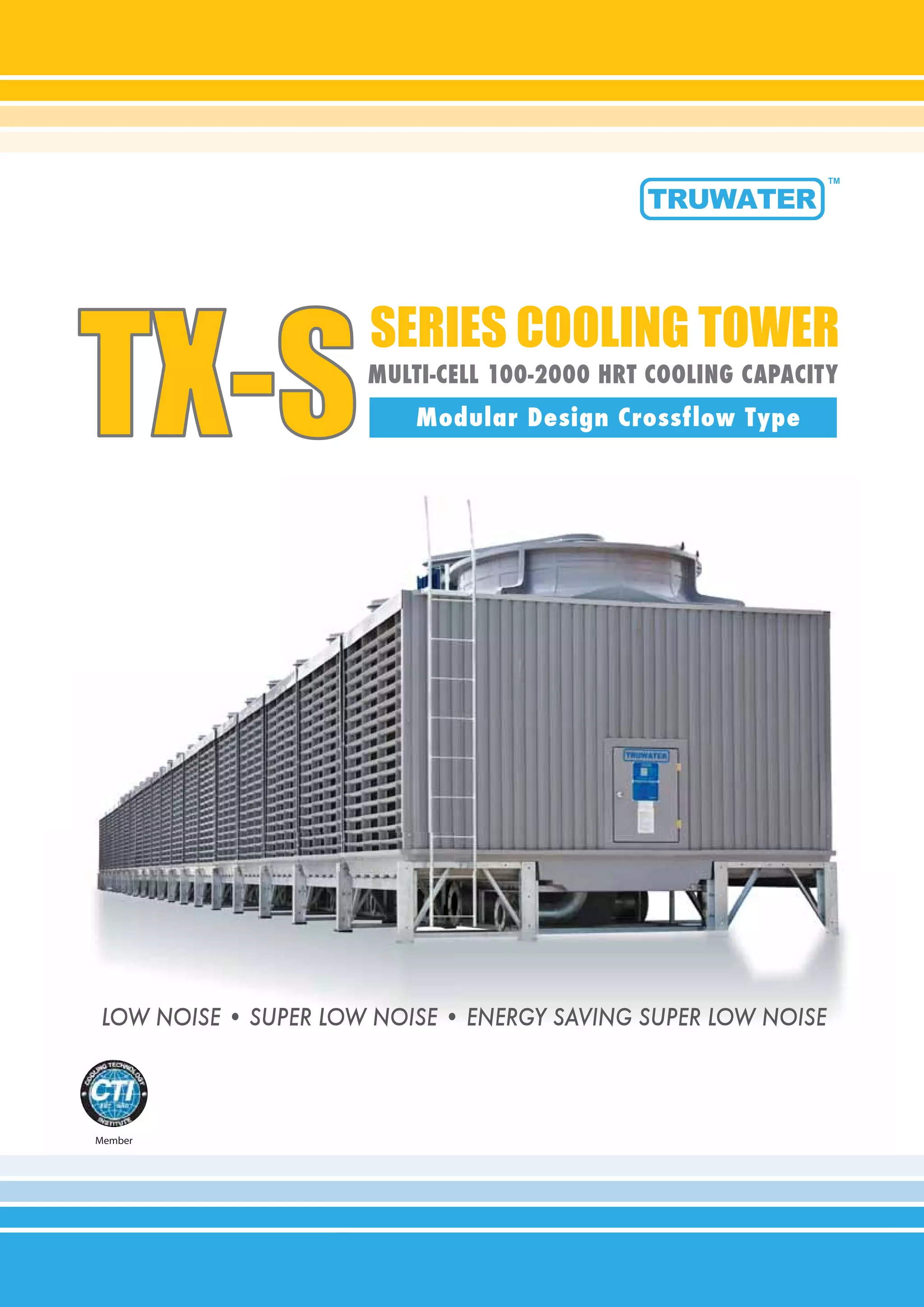
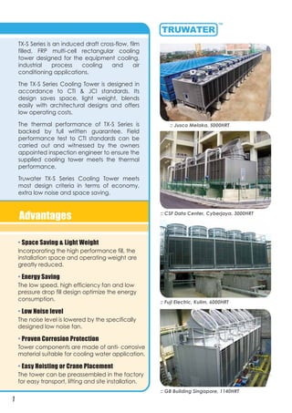
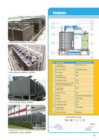
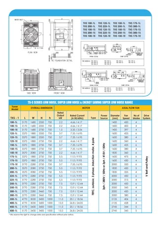
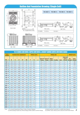
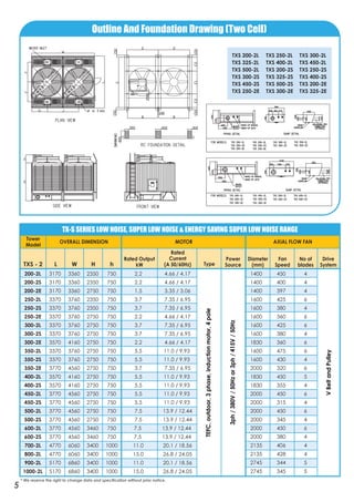
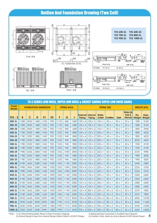
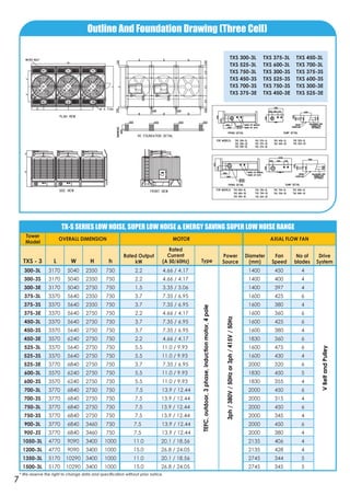
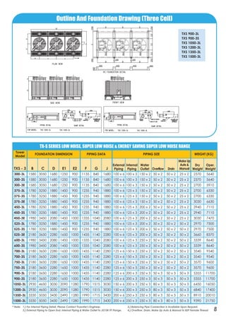
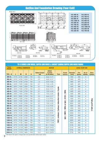
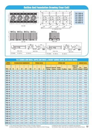
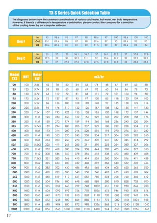
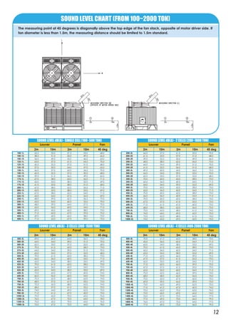
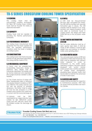
This document summarizes the specifications of a modular, crossflow type cooling tower called the TX-S Series. It has a cooling capacity range of 100-2000 HRT and features a low noise, super low noise, or energy saving super low noise design. The cooling tower is designed according to CTI and JCI standards and offers advantages such as space savings, light weight, low operating costs, and proven corrosion protection. It provides performance specifications, dimensions, motor details, and piping information for various tower models in the series.
2. :: Fuji Electric, Kulim, 6000HRT
:: CSF Data Center, Cyberjaya, 3000HRT
:: Jusco Melaka, 5000HRT
:: GB Building Singapore, 1140HRT
TX-S Series is an induced draft cross-flow, film
filled, FRP multi-cell rectangular cooling
tower designed for the equipment cooling,
industrial process cooling and air
conditioning applications.
The TX-S Series Cooling Tower is designed in
accordance to CTI & JCI standards. Its
design saves space, light weight, blends
easily with architectural designs and offers
low operating costs.
The thermal performance of TX-S Series is
backed by full written guarantee. Field
performance test to CTI standards can be
carried out and witnessed by the owners
appointed inspection engineer to ensure the
supplied cooling tower meets the thermal
performance.
Truwater TX-S Series Cooling Tower meets
most design criteria in terms of economy,
extra low noise and space saving.
• Space Saving & Light Weight
Incorporating the high performance fill, the
installation space and operating weight are
greatly reduced.
• Energy Saving
The low speed, high efficiency fan and low
pressure drop fill design optimize the energy
consumption.
• Low Noise level
The noise level is lowered by the specifically
designed low noise fan.
• Proven Corrosion Protection
Tower components are made of anti- corrosive
material suitable for cooling water application.
• Easy Hoisting or Crane Placement
The tower can be preassembled in the factory
for easy transport, lifting and site installation.
Advantages
1
3. Features
2
:: Tesco Tebrau, Johor, 1750HRT
:: Kotra Pharma, Melaka, 1600HRT
:: Quill Interior Holding, PJ, 2100HRT
:: Sutera Mall, Johor, 2800HRT
No Description Material / Specification
1 V-Belt and
Pulley System
FRP Pulley Cover
2 Fan Assembly Aluminium Alloy
3 Fan Stack FRP
4 Hot Water
Distribution Box
FRP
6 High Performance Film Fill
Pack and Drift Eliminator
PVC
7 Cold Water
Basin Floor
FRP
5 Hot Water Basin FRP
8 Suction Sump FRP
9 Motor Weather Proof TEFC type
10 Ladder HDG Steel
11 Casing / Louver PVC
12 Inspection Door FRP
14 Internal Piping Optional
13 Cold Water
Basin Frame
HDG Steel
5. TX-S SERIES LOW NOISE, SUPER LOW NOISE & ENERGY SAVING SUPER LOW NOISE RANGE
100-1L 1580 3050 1680 1250 900 1135 840 - 100 x 2 100 x 1 100 x 1 50 x 1 50 x 1 25 x 1 790 1880
100-1S 1580 3050 1680 1250 900 1135 840 - 100 x 2 100 x 1 100 x 1 50 x 1 50 x 1 25 x 1 790 1880
100-1E 1580 3050 1680 1250 900 1135 840 - 100 x 2 100 x 1 100 x 1 50 x 1 50 x 1 25 x 1 900 1970
125-1L 1780 3250 1880 1450 900 1235 940 - 100 x 2 125 x 1 125 x 1 50 x 1 50 x 1 25 x 1 900 2110
125-1S 1780 3250 1880 1450 900 1235 940 - 100 x 2 125 x 1 125 x 1 50 x 1 50 x 1 25 x 1 900 2110
125-1E 1780 3250 1880 1450 900 1235 940 - 100 x 2 125 x 1 125 x 1 50 x 1 50 x 1 25 x 1 1010 2210
150-1L 1780 3250 1880 1450 900 1235 940 - 100 x 2 125 x 1 125 x 1 50 x 1 50 x 1 25 x 1 980 2370
150-1S 1780 3250 1880 1450 900 1235 940 - 100 x 2 125 x 1 125 x 1 50 x 1 50 x 1 25 x 1 980 2370
150-1E 1980 3450 2080 1450 1000 1335 1040 - 100 x 2 125 x 1 125 x 1 50 x 1 50 x 1 25 x 1 1010 2490
175-1L 1780 3250 1880 1450 900 1235 940 - 100 x 2 125 x 1 125 x 1 50 x 1 50 x 1 25 x 1 990 2500
175-1S 1780 3250 1880 1450 900 1235 940 - 100 x 2 125 x 1 125 x 1 50 x 1 50 x 1 25 x 1 990 2500
175-1E 2180 3650 2280 1650 1000 1435 1140 - 100 x 2 125 x 1 125 x 1 50 x 1 50 x 1 25 x 1 1220 2790
200-1L 1980 3450 2080 1450 1000 1335 1040 - 100 x 2 125 x 1 150 x 1 50 x 1 50 x 1 25 x 1 1113 2880
200-1S 1980 3450 2080 1450 1000 1335 1040 - 100 x 2 125 x 1 150 x 1 50 x 1 50 x 1 25 x 1 1113 2880
225-1L 2180 3650 2280 1650 1000 1435 1140 - 125 x 2 150 x 1 200 x 1 50 x 1 50 x 1 50 x 1 1180 3180
225-1S 2180 3650 2280 1650 1000 1435 1140 - 125 x 2 150 x 1 200 x 1 50 x 1 50 x 1 50 x 1 1180 3180
250-1L 2180 3650 2280 1650 1000 1435 1140 - 125 x 2 150 x 1 200 x 1 50 x 1 50 x 1 50 x 1 1190 3200
250-1S 2180 3650 2280 1650 1000 1435 1140 - 125 x 2 150 x 1 200 x 1 50 x 1 50 x 1 50 x 1 1190 3200
300-1L 2180 3650 2280 1650 1000 1435 1140 - 125 x 2 200 x 1 250 x 1 50 x 1 50 x 1 50 x 1 1785 3900
300-1S 2180 3650 2280 1650 1000 1435 1140 - 125 x 2 200 x 1 250 x 1 50 x 1 50 x 1 50 x 1 1785 3900
350-1L 2930 4650 3030 2090 1280 1790 1515 - 150 x 2 200 x 1 250 x 1 80 x 1 50 x 1 50 x 1 2150 5350
400-1L 2930 4650 3030 2090 1280 1790 1515 - 150 x 2 200 x 1 250 x 1 80 x 1 50 x 1 50 x 1 2280 5800
450-1L 3330 5050 3430 2490 1280 1990 1715 - 150 x 2 250 x 1 250 x 1 80 x 1 50 x 1 50 x 1 2970 6670
500-1L 3330 5050 3430 2490 1280 1990 1715 - 200 x 2 250 x 1 250 x 1 80 x 1 80 x 1 50 x 1 3130 7250
Tower
Model
FOUNDATION DIMENSION PIPING DATA PIPING SIZE WEIGHT (KG)
TXS - 1 B C D E1 E2 F G J
External
Piping
Internal
Piping
Water
Outlet
Dry
Weight
Oper.
Weight
Make Up
Auto &
ManualOverflow Drain
Outline And Foundation Drawing (Single Cell)
* Note: 1.) For Internal Piping Detail, Please Contact Truwater's Engineer. 2.) Balancing Pipe Connection Is Available Upon Request.
3.) External Piping to Open End. Internal Piping & Water Outlet to JIS10K FF Flange. 4.) Overflow, Drain, Make Up Auto & Manual to BSP Female Thread 4
TXS 350-1L TXS 400-1L TXS 450-1L TXS 500-1L
7. TX-S SERIES LOW NOISE, SUPER LOW NOISE & ENERGY SAVING SUPER LOW NOISE RANGE
200-2L 1580 3050 1680 1250 900 1135 840 1680 100 x 4 100 x 2 150 x 1 50 x 1 50 x 1 25 x 1 1580 3760
200-2S 1580 3050 1680 1250 900 1135 840 1680 100 x 4 100 x 2 150 x 1 50 x 1 50 x 1 25 x 1 1580 3760
200-2E 1580 3050 1680 1250 900 1135 840 1680 100 x 4 100 x 2 150 x 1 50 x 1 50 x 1 25 x 1 1800 3940
250-2L 1780 3250 1880 1450 900 1235 940 1880 100 x 4 125 x 2 200 x 1 50 x 1 50 x 1 50 x 1 1800 4220
250-2S 1780 3250 1880 1450 900 1235 940 1880 100 x 4 125 x 2 200 x 1 50 x 1 50 x 1 50 x 1 1800 4220
250-2E 1780 3250 1880 1450 900 1235 940 1880 100 x 4 125 x 2 200 x 1 50 x 1 50 x 1 50 x 1 2020 4420
300-2L 1780 3250 1880 1450 900 1235 940 1880 100 x 4 125 x 2 250 x 1 50 x 1 50 x 1 50 x 1 1960 4740
300-2S 1780 3250 1880 1450 900 1235 940 1880 100 x 4 125 x 2 250 x 1 50 x 1 50 x 1 50 x 1 1960 4740
300-2E 1980 3450 2080 1450 1000 1335 1040 2080 100 x 4 125 x 2 250 x 1 50 x 1 50 x 1 50 x 1 2020 4980
350-2L 1780 3250 1880 1450 900 1235 940 1880 100 x 4 125 x 2 250 x 1 50 x 1 50 x 1 50 x 1 1980 5000
350-2S 1780 3250 1880 1450 900 1235 940 1880 100 x 4 125 x 2 250 x 1 50 x 1 50 x 1 50 x 1 1980 5000
350-2E 2180 3650 2280 1650 1000 1435 1140 2280 100 x 4 125 x 2 250 x 1 50 x 1 50 x 1 50 x 1 2440 5580
400-2L 1980 3450 2080 1450 1000 1335 1040 2080 100 x 4 125 x 2 250 x 1 50 x 1 50 x 1 50 x 1 2226 5760
400-2S 1980 3450 2080 1450 1000 1335 1040 2080 100 x 4 125 x 2 250 x 1 50 x 1 50 x 1 50 x 1 2226 5760
450-2L 2180 3650 2280 1650 1000 1435 1140 2280 125 x 4 150 x 2 250 x 1 50 x 1 50 x 1 50 x 1 2360 6360
450-2S 2180 3650 2280 1650 1000 1435 1140 2280 125 x 4 150 x 2 250 x 1 50 x 1 50 x 1 50 x 1 2360 6360
500-2L 2180 3650 2280 1650 1000 1435 1140 2280 125 x 4 150 x 2 250 x 1 50 x 1 50 x 1 50 x 1 2380 6400
500-2S 2180 3650 2280 1650 1000 1435 1140 2280 125 x 4 150 x 2 250 x 1 50 x 1 50 x 1 50 x 1 2380 6400
600-2L 2180 3650 2280 1650 1000 1435 1140 2280 125 x 4 200 x 2 250 x 2 50 x 2 50 x 2 50 x 2 3570 7800
600-2S 2180 3650 2280 1650 1000 1435 1140 2280 125 x 4 200 x 2 250 x 2 50 x 2 50 x 2 50 x 2 3570 7800
700-2L 2930 4650 3030 2090 1280 1790 1515 3030 150 x 4 200 x 2 250 x 2 80 x 2 50 x 2 50 x 2 4300 10700
800-2L 2930 4650 3030 2090 1280 1790 1515 3030 150 x 4 200 x 2 250 x 2 80 x 2 50 x 2 50 x 2 4560 11600
900-2L 3330 5050 3430 2490 1280 1990 1715 3430 200 x 4 250 x 2 250 x 2 80 x 2 50 x 2 50 x 2 5940 13340
1000-2L 3330 5050 3430 2490 1280 1990 1715 3430 200 x 4 250 x 2 250 x 2 80 x 2 80 x 2 50 x 2 6260 14500
Tower
Model
FOUNDATION DIMENSION PIPING DATA PIPING SIZE WEIGHT (KG)
TXS - 2 B C D E1 E2 F G J
External
Piping
Internal
Piping
Water
Outlet
Dry
Weight
Oper.
Weight
Make Up
Auto &
ManualOverflow Drain
Outline And Foundation Drawing (Two Cell)
TXS 600-2L TXS 600-2S
TXS 700-2L TXS 800-2L
TXS 900-2L TXS 1000-2L
* Note: 1.) For Internal Piping Detail, Please Contact Truwater's Engineer. 2.) Balancing Pipe Connection Is Available Upon Request.
3.) External Piping to Open End. Internal Piping & Water Outlet to JIS10K FF Flange. 4.) Overflow, Drain, Make Up Auto & Manual to BSP Female Thread 6
9. TX-S SERIES LOW NOISE, SUPER LOW NOISE & ENERGY SAVING SUPER LOW NOISE RANGE
300-3L 1580 3050 1680 1250 900 1135 840 1680 100 x 6 100 x 3 150 x 2 50 x 2 50 x 2 25 x 2 2370 5640
300-3S 1580 3050 1680 1250 900 1135 840 1680 100 x 6 100 x 3 150 x 2 50 x 2 50 x 2 25 x 2 2370 5640
300-3E 1580 3050 1680 1250 900 1135 840 1680 100 x 6 100 x 3 150 x 2 50 x 2 50 x 2 25 x 2 2700 5910
375-3L 1780 3250 1880 1450 900 1235 940 1880 100 x 6 125 x 3 150 x 2 50 x 2 50 x 2 25 x 2 2700 6330
375-3S 1780 3250 1880 1450 900 1235 940 1880 100 x 6 125 x 3 150 x 2 50 x 2 50 x 2 25 x 2 2700 6330
375-3E 1780 3250 1880 1450 900 1235 940 1880 100 x 6 125 x 3 150 x 2 50 x 2 50 x 2 25 x 2 3030 6630
450-3L 1780 3250 1880 1450 900 1235 940 1880 100 x 6 125 x 3 200 x 2 50 x 2 50 x 2 25 x 2 2940 7110
450-3S 1780 3250 1880 1450 900 1235 940 1880 100 x 6 125 x 3 200 x 2 50 x 2 50 x 2 25 x 2 2940 7110
450-3E 1980 3450 2080 1450 1000 1335 1040 2080 100 x 6 125 x 3 200 x 2 50 x 2 50 x 2 25 x 2 3030 7470
525-3L 1780 3250 1880 1450 900 1235 940 1880 100 x 6 125 x 3 200 x 2 50 x 2 50 x 2 50 x 2 2970 7500
525-3S 1780 3250 1880 1450 900 1235 940 1880 100 x 6 125 x 3 200 x 2 50 x 2 50 x 2 50 x 2 2970 7500
525-3E 2180 3650 2280 1650 1000 1435 1140 2280 100 x 6 125 x 3 200 x 2 50 x 2 50 x 2 50 x 2 3660 8370
600-3L 1980 3450 2080 1450 1000 1335 1040 2080 100 x 6 125 x 3 250 x 2 50 x 2 50 x 2 50 x 2 3339 8640
600-3S 1980 3450 2080 1450 1000 1335 1040 2080 100 x 6 125 x 3 250 x 2 50 x 2 50 x 2 50 x 2 3339 8640
700-3L 2180 3650 2280 1650 1000 1435 1140 2280 125 x 6 150 x 3 250 x 2 50 x 2 50 x 2 50 x 2 3540 9540
700-3S 2180 3650 2280 1650 1000 1435 1140 2280 125 x 6 150 x 3 250 x 2 50 x 2 50 x 2 50 x 2 3540 9540
750-3L 2180 3650 2280 1650 1000 1435 1140 2280 125 x 6 150 x 3 250 x 2 50 x 2 50 x 2 50 x 2 3570 9600
750-3S 2180 3650 2280 1650 1000 1435 1140 2280 125 x 6 150 x 3 250 x 2 50 x 2 50 x 2 50 x 2 3570 9600
900-3L 2180 3650 2280 1650 1000 1435 1140 2280 125 x 6 200 x 3 250 x 3 50 x 3 50 x 3 50 x 3 5355 11700
900-3S 2180 3650 2280 1650 1000 1435 1140 2280 125 x 6 200 x 3 250 x 3 50 x 3 50 x 3 50 x 3 5355 11700
1050-3L 2930 4650 3030 2090 1280 1790 1515 3030 150 x 6 200 x 3 250 x 3 80 x 3 50 x 3 50 x 3 6450 16050
1200-3L 2930 4650 3030 2090 1280 1790 1515 3030 150 x 6 200 x 3 250 x 3 80 x 3 50 x 3 50 x 3 6840 17400
1350-3L 3330 5050 3430 2490 1280 1990 1715 3430 200 x 6 250 x 3 250 x 3 80 x 3 50 x 3 50 x 3 8910 20010
1500-3L 3330 5050 3430 2490 1280 1990 1715 3430 200 x 6 250 x 3 250 x 3 80 x 3 80 x 3 50 x 3 9390 21750
Tower
Model
FOUNDATION DIMENSION PIPING DATA PIPING SIZE WEIGHT (KG)
TXS - 3 B C D E1 E2 F G J
External
Piping
Internal
Piping
Water
Outlet
Dry
Weight
Oper.
Weight
Make Up
Auto &
ManualOverflow Drain
Outline And Foundation Drawing (Three Cell)
* Note: 1.) For Internal Piping Detail, Please Contact Truwater's Engineer. 2.) Balancing Pipe Connection Is Available Upon Request.
3.) External Piping to Open End. Internal Piping & Water Outlet to JIS10K FF Flange. 4.) Overflow, Drain, Make Up Auto & Manual to BSP Female Thread 8
TXS 900-3L
TXS 900-3S
TXS 1050-3L
TXS 1200-3L
TXS 1350-3L
TXS 1500-3L
11. TX-S SERIES LOW NOISE, SUPER LOW NOISE & ENERGY SAVING SUPER LOW NOISE RANGE
400-4L 1580 3050 1680 1250 900 1135 840 1680 100 x 8 100 x 4 150 x 2 50 x 2 50 x 2 25 x 2 3160 7520
400-4S 1580 3050 1680 1250 900 1135 840 1680 100 x 8 100 x 4 150 x 2 50 x 2 50 x 2 25 x 2 3160 7520
400-4E 1580 3050 1680 1250 900 1135 840 1680 100 x 8 100 x 4 150 x 2 50 x 2 50 x 2 25 x 2 3600 7880
500-4L 1780 3250 1880 1450 900 1235 940 1880 100 x 8 125 x 4 200 x 2 50 x 2 50 x 2 50 x 2 3600 8440
500-4S 1780 3250 1880 1450 900 1235 940 1880 100 x 8 125 x 4 200 x 2 50 x 2 50 x 2 50 x 2 3600 8440
500-4E 1780 3250 1880 1450 900 1235 940 1880 100 x 8 125 x 4 200 x 2 50 x 2 50 x 2 50 x 2 4040 8840
600-4L 1780 3250 1880 1450 900 1235 940 1880 100 x 8 125 x 4 250 x 2 50 x 2 50 x 2 50 x 2 3920 9480
600-4S 1780 3250 1880 1450 900 1235 940 1880 100 x 8 125 x 4 250 x 2 50 x 2 50 x 2 50 x 2 3920 9480
600-4E 1980 3450 2080 1450 1000 1335 1040 2080 100 x 8 125 x 4 250 x 2 50 x 2 50 x 2 50 x 2 4040 9960
700-4L 1780 3250 1880 1450 900 1235 940 1880 100 x 8 125 x 4 250 x 2 50 x 2 50 x 2 50 x 2 3960 10000
700-4S 1780 3250 1880 1450 900 1235 940 1880 100 x 8 125 x 4 250 x 2 50 x 2 50 x 2 50 x 2 3960 10000
700-4E 2180 3650 2280 1650 1000 1435 1140 2280 100 x 8 125 x 4 250 x 2 50 x 2 50 x 2 50 x 2 4880 11160
800-4L 1980 3450 2080 1450 1000 1335 1040 2080 100 x 8 125 x 4 250 x 2 50 x 2 50 x 2 50 x 2 4452 11520
800-4S 1980 3450 2080 1450 1000 1335 1040 2080 100 x 8 125 x 4 250 x 2 50 x 2 50 x 2 50 x 2 4452 11520
900-4L 2180 3650 2280 1650 1000 1435 1140 2280 125 x 8 150 x 4 250 x 2 50 x 2 50 x 2 50 x 2 4720 12720
900-4S 2180 3650 2280 1650 1000 1435 1140 2280 125 x 8 150 x 4 250 x 2 50 x 2 50 x 2 50 x 2 4720 12720
1000-4L 2180 3650 2280 1650 1000 1435 1140 2280 125 x 8 150 x 4 250 x 2 50 x 2 50 x 2 50 x 2 4760 12800
1000-4S 2180 3650 2280 1650 1000 1435 1140 2280 125 x 8 150 x 4 250 x 2 50 x 2 50 x 2 50 x 2 4760 12800
1200-4L 2180 3650 2280 1650 1000 1435 1140 2280 125 x 8 200 x 4 250 x 4 50 x 4 50 x 4 50 x 4 7140 15600
1200-4S 2180 3650 2280 1650 1000 1435 1140 2280 125 x 8 200 x 4 250 x 4 50 x 4 50 x 4 50 x 4 7140 15600
1400-4L 2930 4650 3030 2090 1280 1790 1515 3030 150 x 8 200 x 4 250 x 4 80 x 4 50 x 4 50 x 4 8600 21400
1600-4L 2930 4650 3030 2090 1280 1790 1515 3030 150 x 8 200 x 4 250 x 4 80 x 4 50 x 4 50 x 4 9120 23200
1800-4L 3330 5050 3430 2490 1280 1990 1715 3430 200 x 8 250 x 4 250 x 4 80 x 4 50 x 4 50 x 4 11880 26680
2000-4L 3330 5050 3430 2490 1280 1990 1715 3430 200 x 8 250 x 4 250 x 4 80 x 4 80 x 4 50 x 4 12520 2900
Tower
Model
FOUNDATION DIMENSION PIPING DATA PIPING SIZE WEIGHT (KG)
TXS - 4 B C D E1 E2 F G J
External
Piping
Internal
Piping
Water
Outlet
Dry
Weight
Oper.
Weight
Make Up
Auto &
ManualOverflow Drain
Outline And Foundation Drawing (Four Cell)
TXS 1200-4L
TXS 1200-4S
TXS 1400-4L
TXS 1600-4L
TXS 1800-4L
TXS 2000-4L
* Note: 1.) For Internal Piping Detail, Please Contact Truwater's Engineer. 2.) Balancing Pipe Connection Is Available Upon Request.
3.) External Piping to Open End. Internal Piping & Water Outlet to JIS10K FF Flange. 4.) Overflow, Drain, Make Up Auto & Manual to BSP Female Thread 10
14. When a cooling tower is located near a wall,
consideration must be given to the clearance distance
between the air inlets of the tower and the wall
structure(s). See Figure 2, Recommended Dimensions D1
and D2.
The minimum dimensions, D1 and D2, as shown in Table
1 must be maintained to ensure that the unit is provided
adequate air flow. In some installation, consideration
must also be given to access to the unit for
maintenance. Room must be provided for piping,
removals of access panels, etc.
Sometimes other pieces of equipment such as pumps,
filters, piping etc are placed in front of the air inlets.
These obstructions should not be located any closer
than the minimum dimensions in Table 1.
RECOMMENDED UNIT LAYOUT
It is advisable to select and design the best layout or location to avoid air recirculation. Recirculation occurs when some of
the hot moist discharge air leaving the cooling tower flows back into the fresh air inlet.
The following guidelines will provide the best location or layout which will minimize recirculation, maximize fresh air flow and
allow adequate maintenance accessibility.
FIGURE 2 :
Installation next
to a wall.
The best place for TX-S Series Cooling Tower is in an open space. However, when this is not possible, correct layout
guidelines must be followed to provide satisfactory installation.
Ensure that the top of the cooling tower is higher than any adjacent walls, buildings or other structures.
Figure 1(a) and 1(b) are examples of incorrect installation. These conditions can be corrected by elevating the unit on
structural steel/concrete plinths so that the top is higher that the wall as shown in Figure 1(c).
A. SINGLE UNIT INSTALLATIONS
FIGURE: 1(a) FIGURE: 1(b) FIGURE: 1(c)
: Wind effect with top of unit lower than top of wallINCORRECT CORRECT : Installation elevated so that top of unit is
higher than top of wall
TABLE 2
Tower Model
TXS
End Wall
Length, L mm
Minimum Dimension, mm
D3 (End-to-End)
Tower Model
TXS
Louver Width,
W mm
Minimum Dimension, mm
D4 (Side-by-Side)
All models All sizes 1000
200-2L ~ 600-2L Below 4500 3000
700-2L ~ 1000-2L Below 7000 3500
400-3E ~ 550-3E
600-3L ~ 700-3L
600-3S ~ 700-3S
1050-3L ~ 1200-3L Below 10000 5000
600-4E ~ 700-4E
800-4L ~ 1000-4L
800-4S ~ 1000-4S
1350-3L ~ 1500-3L Below 14000 6000
1400-4L ~ 2000-4L
The minimum dimensions are as listed in Table 2
TABLE 1
Tower Model Minimum Dimension (mm)
TXS D1 (At Louver Side) D2 (At Panel Side)
100-1,125-1, 1500 1500
150-1,175-1
200-1,225-1, 2000 1500
250-1,300-1
350-1,400-1, 2500 1500
450-1,500-1
13
15. When more than one cooling tower is installed at the same
location, recirculation becomes a bigger problem.
With the installations of two cooling towers, they should be
placed end to end with the narrows ends adjacent as
shown in Figure 3. Another method is to locate the units
side-by-side with the longer sides parallel to each other as
shown in Figure 4. In either configuration, the distance
between the units must provide adequate airflow as well
as room for piping to the unit and access for maintenance.
B. MULTIPLE UNIT INSTALLATIONS
TX-S Series Cooling Tower can also be installed in enclosures
with louvered or slotted walls and an open top (Figure 6)
with this type of enclosure, the air flow patterns will be a
mixture of the open type and well installation. The inlet air
will be drawn from the top as well as through the louvers or
slots.
When considering a multiple-cell unit located in a louvered
wall enclosures, the D7 and D8 dimensions, found in Table
4, must be used as absolute minimums.
Louvered Wall Enclosures
1) Solid Wall Enclosures or Wells
Figure 5 shown a cooling tower is installed in a well. When
considering a multiple-cell unit located in a well, the D5
and D6 dimensions, found in Table 3, must be used as
absolute minimums.
SPECIAL ENCLOSURE INSTALLATION
Tower Model
TXS
End Wall
Length, L mm
Minimum Dimension, mm
D7 (End Wall Panel Side)
Tower Model
TXS
Louver Width,
W mm
Minimum Dimension, mm
D8 (Louver Side to Louvered wall)
All sizes 2500
All models All sizes 1000
All models
TABLE 3
Tower Model
TXS
End Wall
Length, L mm
Minimum Dimension, mm
D5 (End Wall Panel Side)
Tower Model
TXS
Louver Width,
W mm
Minimum Dimension, mm
D6 (Louver Side to Solid wall)
All models All sizes 1000
200-2L ~ 600-2L Below 4500 3500
700-2L ~ 1000-2L Below 7000 4000
400-3E ~ 550-3E
600-3L ~ 700-3L
600-3S ~ 700-3S
1050-3L ~ 1200-3L Below 10000 6000
600-4E ~ 700-4E
800-4L ~ 1000-4L
800-4S ~ 1000-4S
1350-3L ~ 1500-3L Below 14000 6000
1400-4L ~ 2000-4L
14
FIGURE 3: MULTIPLE UNITS PLACED END TO END
FIGURE 4: MULTIPLE UNITS PLACED SIDE-BY-SIDE
The unit should be oriented so that the air flow uniformly to
the air inlets on all louver sides of the unit. The air discharge
of the unit must be level with or higher than surrounding
walls.
FIGURE 6: LOUVERED WALL ENCLOSURE
16. TX-S SERIES CROSSFLOW COOLING TOWER SPECIFICATION
Truwater Cooling Towers Sdn Bhd (188113-A)
Executive Suite 702, Block B, Kelana Business Centre, No. 97, Jalan SS7/2, Kelana Jaya, 47301 Petaling Jaya, Selangor, Malaysia.
Tel. : +603 7880 8800 Fax : +603 7804 5519
E-mail : Tw.Cooling@truwater.com.my Website : www.truwater.com.my
1.0 GENERAL
The cooling tower shall be
induced-draft, crossflow, rectangular,
film filled, FRP Cooling Tower. Cooling
tower shall be Truwater TX-S Series or
approved equivalent.
2.0 CAPACITY
Cooling Tower shall be capable of
providing the thermal performance
scheduled.
3.0 PERFORMANCE WARRANTY
The cooling tower manufacturer shall
guarantee that the tower supplied will
meet the specified performance
conditions when the tower is installed
according to plans.
4.0 CONSTRUCTION
The cooling tower main frame structure
shall be hot dip galvanized steel (HDG).
The casing shall be made of PVC.
5.0 MECHANICAL EQUIPMENT
5.1 Fan(s) shall be propeller-type,
incorporating heavy-duty blades of
aluminum alloy. Blades shall be
individually adjustable. Fan blades shall
be factory balanced and assembled.
Pitch angle should be variable to allow
flexibility.
5.2 The V-belts shall be of rubber with
fabric impregnated able to withstand
the adverse ambient conditions of 50°C
and 100% R.H. The pulleys shall be cast
iron with the grooves of standard
dimensions. The entire V-belt & pulley
set must be fully enclosed in a FRP
molded case to protect the v-belts from
in contact with the humid discharge air.
5.3 Motor(s) shall be TEFC,
weatherproof sq. caged induction type
suitable for 3ph /50Hz/415V power
supply and with 1450 rpm. Motor shall
be installed outside the discharge air
stream.
6.0 INFILL
6.1 Infill shall be Vacuum-formed
film-type, rigid, corrugated PVC sheets.
The infill shall be bonded with specially
formulated glue in blocks. The infill
modules shall be resistant to rot, fungi,
bacteria and organic/inorganic acids
and alkali as commonly found in
cooling towers. The design shall meet
0.02% drift loss of the circulation water
flow.
7.0 HOT WATER DISTRIBUTION
SYSTEM
The hot water distribution shall be of
open gravity type basin. It shall be
made of FRP material. It shall be light
weight and non-corrosive to maintain
stable water sprinkling effect.
8.0 COLD WATER BASIN
The cold water basin shall be of FRP and
supported on HDG steel framework. The
basin shall be designed with sufficient
water capacity to avoid air
entrainment in the outlet during
operating conditions. The basin shall be
equipped with suction strainer,
make-up ball valve, overflow and drain.
For multiple tower arrangement,
equalizing pipes between basins shall
be provided to maintain the same level
of water in each basin.
9.0 ACCESS AND SAFETY
Ladder shall be provided for inspection
& maintenance purposes. HDG steel
fan guard shall be provided over each
fan cylinder.
PVC Casing
HDG Steel Structure
TCT/B/003
Mechanical Equipment
Hot Water Basin