ABSTRACT
Thetechnique of augmented reality (AR) is to augment 3D virtual objects into
real images. Individual can interact with 3D virtual objects using tracking and
registration methods. Visual tracking is the most popular tracking approach used in
AR system, and markers are simply and generally used for identification and
tracking. Moreover, natural feature or marker-less identification and tracking is
getting more and more important and can be widely used in numerous applications.
Therefore, many natural feature extraction and object tracking schemes are
developed to efficiently identify and track natural objects. However, few of
platforms are designed to verify different tracking algorithms for AR system. In this
thesis, a novel tracking verification platform for AR environment, ARStudio, is
proposed. ARStudio is on the basis of ARToolKit, and integrates the library of
OpenCV and OpenGL. Furthermore, we modularize each component such as image
capture, image transform, visual tracking, image rendering, for the purpose of
independent usage and design. Users can select different displaying windows, and
easily demonstrate results by using drag and drop. Experimental results manifest that
ARStudio can be used for the purpose of verifying tracking schemes and AR
applications.
:
Keywords Augmented Reality, Markerless, Virtual Reality, Visual Tracking, Feature
Tracking, Natural Features.
iv
圖 2.36 針孔攝影機模型[52]。
在圖2.36中可看到兩個相似三角形,利用相似三角形原理推得:
h H H
或 h f
f D D (2.1)
其中各個參數說明如下:
(1) f 是攝影機焦距。
(2) D 是攝影機到物體的距離。
(3) H 是物體實際高度。
(4) h 是 Image plane 中物體的圖像高度。
將整個應用擴展到三維空間,並將整個光學軸(Optical Axis)往下移位,其
目的在於消除負號,讓所有的計算都在光學軸之上。在基本的針孔攝影機模型
中,將投影中心放置在歐氏座標系統(Euclidean Coordinate)的原點,並將影像平
面放置在Z 軸上距離原點為 f 的位置。在此針孔攝影機模型之下,一個在三維
空間的點 Q (X, Y, Z) T ,其投影至二維影像上的q點,其中 q ( x screen , y screen ) 。也就
是由投影中心與三維座標點Q之連線和成像平面之交點,如圖 2.37所示。
35
48.
圖 2.37 針孔攝影機模型之投影關係圖[52]。
將座標為 ( X , Y , Z ) 之物理點 Q 映射到投影平面上座標為 ( x screen , y screen ) 之點q的
過程稱為投影變換(Projective Transform),而齊次座標可把維度為n的投影空間
上的點用(n+1)維向量表示;換句話說,二維平面投影空間,可以使用一個三維
向量 q (q1 , q 2 , q 3 ) 來表示該平面的點,如公式(2.2)所示,其中λ為一比例係數,
因為投影空間上的所有比例不變,因此可以透過除以 q 3 來計算實際之像素座標
值。
xq q1
y q
q 2 (2.2)
f
q3
藉由前面所提之相似三角形的原理,可推算出三維座標點 Q (X, Y, Z) T 投影
X Y
到影像平面上之二維點 q ( f , f ) T ,故可獲得從三維空間投影至二維空間之
Z Z
映射關係。其中的投影中心又稱之為攝影機中心(Camera Center)或光學中心
(Optical Center),Z軸稱之為主軸(Principal Axis),而主軸與影像平面的交點稱之
為主點(Principal Point)。對於大部分影像呈現採用矩形而非正方形,故針對X軸
與Y軸分別定義兩個不同之焦距 f x 與 f y ,透過公式 (2.1)推得投影平面上座標:
36
49.
H X
x screen f x f x
D Z
(2.3)
H Y
y screen f y f y
D Z
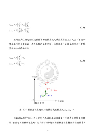
然而公式(2.3)是在假設影像平面座標系統之原點是落在主點之上。不過事
實上並不完全是如此,其與主點的位置會有一位移存在,如圖 2.38所示。重新
整理如公式(2.4)所示:
X
x screen f x c x
Z
(2.4)
Y
y screen f y c y
Z
圖 2.38 影像座標系統 ( x, y ) 與攝影機座標系統 ( xcam , y cam ) 。
從公式(2.4)中可知 c x 與 c y 分別代表x與y上的偏移量,不過為了便於後續討
論,在此暫且將移位值忽略。接下來討論如何從攝影機座標系轉成影像座標系,
37
50.
f
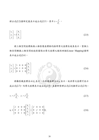
將公式(2.2)重新定義表示成公式(2.5),其中 。
Zc
xc X c
y Y
c c (2.5)
f
Zc
將三維空間座標點與二維影像座標點均採用齊次座標系統來表示,整個三
維空間轉換二維空間的投影關係以齊次座標之線性映射(Linear Mapping)重新
表示成公式(2.6)。
X c
x c 1 0 0 0
y 0 1 0 0 Yc
c Z (2.6)
f 0 0 1 0 c
1
將攝影機座標系以 Q c 表示,而影像座標系以 qi 表示。故非齊次座標可表示
成公式(2.7),而齊次座標表示成公式(2.8),並重新整理公式(2.6)推得公式(2.9)。
Xc Yc
xi f , yi f (2.7)
Zc Zc
X
f 0 0 0 c f 0 0 0
qi 0 0 0 c 0 0 0 Q c
Y
f Z f (2.8)
0
0 1 0 c 0
1 0 1 0
38
51.
X
fXc f 0 0 0 c f 0 0 0
fY 0 0 0 c 0 0 0Qc
Y
f Z f (2.9)
c
Zc 0
0 1 0 c 0
1 0 1 0
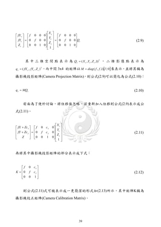
其 中 三 維 空 間 點 表 示 為 Qc ( X c , Yc , Z c ,1) T , 二 維 影 像 點 表 示 為
q c ( fX c , fYc , Z c ) T ,而中間 3x4 的矩陣以 M diag ( f , f ,1)I | 0 來表示,並將其稱為
攝影機投影矩陣(Camera Projection Matrix),則公式(2.9)可以簡化為公式(2.10):
q c MQc (2.10)
前面為了便於討論,將位移值忽略,若重新加入位移則公式(2.9)表示成公
式(2.11)。
X
fX Zc x f 0 cx 0 c
fY Zc 0 f cy 0 c
Y
y Z (2.11)
Z 0
0 1 0 c
1
再將其中攝影機投影矩陣的部分表示成下式:
f 0 cx
K 0
f cy
(2.12)
0
0 1
則公式(2.11)式可被表示成一更簡潔的形式如(2.13)所示,其中矩陣K稱為
攝影機校正矩陣(Camera Calibration Matrix)。
39
52.
q c K I | 0Qc (2.13)
一般而言,在真實空間下的三維座標皆以世界座標系統來表示,而非以相
機座標系統(Camera Coordinate),所以在這之間還有一個座標轉換的動作,在二
個座標系統之間的關係,可用旋轉(Rotation)與位移(Translation)來轉換,如圖
2.39所示。
( R, t ) X w
Y
Qw w
Zw
1
x
q
y
圖 2.39 世界座標系統 Q w 與攝影機座標系統 Q c 之轉換圖[52]。
假設 Q 為一在世界座標系統下之三維座標點,齊次座標點以
Q w (X w , Yw , Z w ,1) T 表示;而 Q c 表示為在相機座標系統下之相對三維座標點,則
Q w 與 Q c 之關係可經由一位移矩陣T與一旋轉矩陣R來表示,其中位移向量t表示
攝影機在世界座標系統之位置,而R表示攝影機之方向,故將之表示成公式
40
53.
(2.14):
R11 R12 R13 T1 X w
R R23 T2 Yw R3 x 3 T3 x1 Rt
R22 R
Qc 21
Q w 0 T
R33 T3 Z w 01x 3 1
Qw (2.14)
R31 R32
T
1 4x4
0 0 0 1 1
並將之導入公式(2.13)式,則可得
X w
f cx
Rt Yw
0
R
q 0 cy T KRI | t Qw
1 Z w
f 0 (2.15)
0 0 1
1
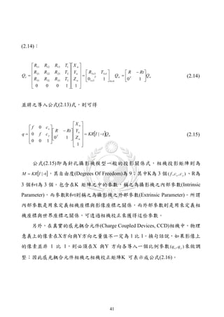
公式(2.15)即為針孔攝影機模型一般的投影關係式,相機投影矩陣則為
M KRI | -t ,其自由度(Degrees Of Freedom)為 9;其中K為 3 個 ( f , c x , c y ) 、R為
3 個和t為 3 個。包含在K 矩陣之中的參數,稱之為攝影機之內部參數(Intrinsic
Parameter),而參數R和t則稱之為攝影機之外部參數(Extrinsic Parameter)。所謂
內部參數是用來定義相機座標與影像座標之關係,而外部參數則是用來定義相
機座標與世界座標之關係,可透過相機校正來獲得這些參數。
另外,在真實的感光耦合元件(Charge Coupled Devices, CCD)相機中,物理
意義上的像素在X方向與Y方向之量值不一定為 1 比 1。換句話說,如果影像上
的像素並非 1 比 1,則必須在X 與Y 方向各導入一個比例參數 (q x , q y ) 來做調
整;因此感光耦合元件相機之相機校正矩陣K 可表示成公式(2.16)。
41
54.
fx 0 cx
K 0
fy cy
(2.16)
0
0 1
其中, f x fq x , f y fq y 。另外,在感光耦合元件相機中,在物理意義上的
像素也不一定是矩形,而 X 軸與 Y 軸有一歪斜的參數 s ,最後將整個完整的
感光耦合元件相機校正矩陣表示為:
fx s cx
K 0
fy cy
(2.17)
0
0 1
因此整個呈現過程是經過多重的座標系統轉換,若不考慮過多的參數,則
針孔攝影機模型之投影可用公式(2.18)表示 對於整個攝影機之參數矩陣計算採
。
用Heikkila和Silven[22]的方法,這也是OpenCV內部所採用之方法。
1 0 0 0
R Rt
q K 0 1 0 0 T Qw K R | Rt Qw MQw
1
0 (2.18)
0 0 1 0
重新整理各個參數說明如下:
(1) 二維影像上的 q 點。
(2) 三維座標點 Q。
(3) 三維齊次座標點 Qw。
(4) 三維攝影機座標點 Qc。
(5) M 稱為攝影機投影矩陣。
(6) K 稱為攝影機校正矩陣。
42
型。然後,使用目前的圖像中減去背景圖片來偵測移動像素。其中影像片段中
固定不變的部份視作背景,再將每一畫格上的像素與背景影像進行相減後得到
差異強度影像,若差異大於給定之門檻值,則視該點為移動像素或稱之為前景,
但它對不斷的明暗變化和移動的攝影機處理效果不彰。
I ( x, y ), if I k ( x, y ) Bk ( x, y ) Td
Fk ( x, y ) k (2.19)
0, Otherwise
其中 Fk ( x, y ) 代表第 k 個畫格時,前景影像 Fk 上點 ( x, y) 的灰階值,灰階值等
於 0 就代表該點屬於背景; I k 為第 k 個畫格的影像; Bk 為第 k 的畫格時的背
景影像; Td 為差異強度門檻值。
背景影像相減法最為關鍵之地方在於一開始如何從影像片段中擷取出背
景,目前也已經有許多不同的方法被提出,最常見的有Longa等人[24]的採取訓
練片段進行平均之平均法以及Lai等人[25]的統計每個像素上灰階值出現頻率之
投票法。
2.3.2.2. 時序差異法
時序相減法最大的優點是不必預先產生背景影像,其基本運作方式是將連
續影像中的前後兩個畫格直接相減後得到差異強度影像,再配合門檻值分離出
前景影像,如公式(2.20)所示:
I ( x, y ), if I k ( x, y ) I k 1 ( x, y ) Td
Fk ( x, y ) k (2.20)
0, Otherwise
其中 Fk ( x, y ) 代表第 k 個畫格時,前景影像 Fk 上點 ( x, y ) 的灰階值,灰階值
47
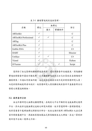
表 3-1 擴增實境現有技術整理。
無標記
名稱 標記 語言
圖片 實體物件
ARToolkit C
ARToolKit Professional C
ARTag C
ARToolKit Plus C
Goblin XNA C#
DART Director
Unifeye C#
Vizard Python
D’Fusion Script
當然除了本文整理的擴增實境套件外,還有開發套件未被提及,因為擴增
實境的開發套件真的不勝枚舉,尤其擴增實境技術正如火如荼的在各個領域中
擴展開來;不過如同前面所提,這些技術的開發目的不是針對影像研究人員,
而是針對終端使用者而設計,故影像研究人員很難從既有套件中直接套用自行
發展之視覺追蹤模組。
3.2. 採用套件分析
本文所要研究之無標記擴增實境,在既有之平台中雖然有支援無標記應用
平台,然而並非支援無標記追蹤之研究而開發,故不管選用哪一套開發環境,
依然需要著手處理無標記開發設計部分,故本文預計採用 ARToolKit 之函式庫
當作開發基礎平台,再搭配影像相關函式庫來驗證本文之理論,在這一節則針
對所需平台做一簡單之介紹。
60
73.
3.2.1. ARtoolKit
ARToolKit 是計算機視覺追蹤函式庫,允許建立擴增實境應用程序將虛擬
影像疊加在真實世界中。要做到這一點,利用視訊追蹤能力,並即時計算標記
相對於攝像機之位置和方向。找到相關位置後,利用 OpenGL(Open Graphic
Library)繪製三維虛擬物件並準確地疊加在標記之上。所以針對擴增實境之標記
應用,ARToolKit 解決了「標記追蹤」與「虛擬物件互動」這兩個關鍵技術。
ARToolKit的最初是由奈良科學技術研究所(Nara Institute of Science and
Technology)的Kato等人[7]於 1999 年所開發,並且被公佈在華盛頓大學的HIT
實驗室(University of Washington HIT Lab) 目前可以從SourceForge[73]取得這個
。
套件開放原始碼,至於更完善之商業版本則可從ARToolWorks[77]中取得相關資
訊。
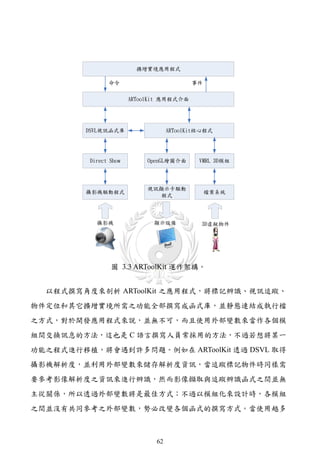
ARToolKit是一套跨平台的函式庫 在不同平台之硬體處理部分可能略有不
,
同,而本文將在Windows環境上實作,故只針對ARToolKit在Windows上之架構
做一討論,如圖 3.3為ARToolKit運作架構圖,其透過DSVL(Direct Show Video
Library)函式庫來取得攝影機之影像,及透過載入VMRL格式之三維物件模型,
最後利用OpenGL進行三維繪製作業,當然ARToolKit的核心程式部分包含了標
記之視訊追蹤與物件之定位,至於詳細運作則不在此介紹。
61
參考文獻
[1] Sutherland, I.E., “The Ultimate Display,” Proceedings of IFIP Congress, pp.
506-508, 1965.
[2] Sutherland, I. E., “A Head-Mounted Three Dimensional Display,” Proceedings of
the AFIPS Fall Joint Computer Conference, pp. 757-764, 1968.
[3] Dixon, S., “A History of Virtual Reality in Performance,” International Journal
of Performance Arts and Digital Media, Vol. 2 No. 1, pp. 23-54, 2006.
[4] Haller, M., Billinghurst, M., and Thomas, B., “Emerging Technologies of
Augmented Reality Interfaces and Design,” Idea Group Publishing, USA,
Chap.13, pp. 262, 2006.
[5] Milgram, P., Takemura, H., Utsumi, A. and Kishino, F., “Augmented Reality: A
Class of Displays on the Reality-Virtuality Continuum,” Telemanipulator and
Telepresence Technologies, SPIE Proceedings Vol. 2351, pp. 282-292,
November, 1994.
[6] Azuma, R., “A Survey of Augmented Reality,” Presence: Teleoperators and
Virtual Environments, Vol. 6, No. 4, pp. 355-385, August 1997.
[7] Kato, H. and Billinghurst, M., “Marker Tracking and HMD Calibration for a
Video-Based Augmented Reality Conferencing System,” in IWAR ’99:
Proceedings of the 2nd, IEEE and ACM International Workshop on Augmented
Reality, pp. 85-94, IEEE Computer Society, 1999.
[8] Kan, T. W., Teng C.H. and Chou, W. S., “Applying QR Code in Augmented
Reality Applications,” International Conference on Virtual Reality Continuum
and Its Applications in Industry, Yokohama, Japan, pp. 253-257, December,
2009.
[9] Gordon, I. and Lowe, D. G., “Scene Modeling, Recognition and Tracking with
Invariant Image Features,” International Symposium on Mixed and Augmented
4
87.
Reality (ISMAR), Arlington,VA, pp. 110-119, 2004.
[10] Gordon, I. and Lowe, D. G., “What and Where: 3D Object Recognition with
Accurate Pose,” Toward Category-Level Object Recognition, Springer-Verlag,
pp. 67-82, 2006.
[11] Yuana, M.L., Ongb, S.K., Nee, A.Y.C., “A Generalized Registration Method for
Augmented Reality Systems,” Computers & Graphics Vol. 29, Issue 6, pp.
980-997, December, 2005.
[12] Vallino, J. R., “Interactive Augmented Reality”, PhD Thesis, Department of
Computer Science, University of Rochester, New York, The USA, 1998.
[13] Billinghurst, M., Kato, H. and Poupyrev, I., “The MagicBook: A Transitional
AR Interface,” Computers & Graphics, Vol. 25, Issue 5, pp. 745-753, 2001.
[14] Bötschi, K., Voegtli, B., Juchli, P., Fjeld, M., Fredriksson, J., Ejdestig, M. and
Duca, F., “Tangible User Interface for Chemistry Education: Comparative
Evaluation and Re-Design,” in CHI ’07: Proceedings of the SIGCHI conference
on Human factors in computing systems, pp. 805-808, May, 2007.
[15] Shelton, B. E. and Hedley, N. R., “Using Augmented Reality for Teaching
Earth-Sun Relationships to Undergraduate Geography Students,” First IEEE
International Augmented Reality Toolkit Workshop, Darmstadt, Germany,
September, 2002.
[16] Shelton, B. E., “How Augmented Reality Helps Students Learn Dynamic
Spatial Relationships,” Ph.D. Dissertation, College of Education, University of
Washington, 2003.
[17] Samset, E., Schmalstieg, D., Sloten, J. V., Freudenthal, A., Declerck, J.,
Casciaro, S., Rideng, Ø., Gersak, B., “Augmented Reality in Surgical
Procedures,” Proceedings of SPIE Medical Imaging, Vol. 6806, Issue 1, pp.
68060K-68060K-12, February, 2008.
[18] Fischer, J., Neff, M., Freudenstein D. and Bartz1, D., “Medical Augmented
Reality Based on Commercial Image Guided Surgery,” Eurographics
5
88.
Symposium on VirtualEnvironments, pp. 83-86, 2004.
[19] Henderson, S., and Feiner, S., “Evaluating the Benefits of Augmented Reality
for Task Localization in Maintenance of an Armored Personnel Carrier Turret,”
Proceeding of IEEE International Symposium on Mixed and Augmented
Reality, pp. 135-144, October 2009.
[20] Vlahakis, V., KARigiannis, J., Tsotros, M., GounARis, M., Almeida, L.,
Stricker, D., Gleue, T., Christou, I.T., CARlucci, R., Ioannidis, N.,
“ARcheoguide: First Results of an Augmented Reality, Mobile Computing
System in Cultural Heritage Sites,” ACM International Conference on Virtual
Reality, ARcheology, and Cultural Heritage, pp.131-140, 2001.
[21] Huang, C. R., “The Vision-Base Interaction on Augmented Exhibition
Environments,” Ph.D. Dissertation, Department of Electrical Engineering,
National Cheng Kung University Tainan, Taiwan, R.O.C., June, 2005.
[22] Heikkila, J. and Silven, O., “A Four-Step Camera Calibration Procedure with
Implicit Image Correction,” In Proc. of IEEE Computer Vision and Pattern
Recognition, pp. 1106-1112, 1997.
[23] Hu, W., Tan, T., Wang, L. and Maybank, S., “A Survey on Visual Surveillance
of Object Motion and Behaviors,” IEEE Transactions on Systems, Man and
Cybernetics, Part C: Applications and Reviews, Vol. 34, pp. 334-352, 2004.
[24] Longa, W. and Yang, Y. H., “Stationary Background Generation: An Alternative
to the Difference of Two Images,” Vol. 23, No. 12, pp. 1351-1359, 1990.
[25] Lai, Andrew H. S. and Yung, Nelson H. C., “A Fast and Accurate Scoreboard
Algorithm for Estimating Stationary Background in an Image Sequence,” Proc.
of IEEE Int’l Symp. on Circuits and Systems, Vol. 4, 241-244, 1998.
[26] Lucas, B. D. and Kanade, T., “An Iterative Image Registration Technique with
an Application to Stereo Vision,” Proceedings of Imaging Understanding
Workshop, pp. 121-130, 1981.
[27] Horn, B.K.P. and Schunck, B.G., “Determining Optical Flow,” Artificial
6
89.
Intelligence, Vol. 17,pp. 185-203, 1981.
[28] Zang, Q. and Klette, R., “Object Classification and Tracking in Video
Surveillance,” Computer Analysis of Images and Patterns, Vol. 2756, pp.
198-205, August, 2003.
[29] Paragios N.and Deriche, R., “Geodesic Active Contours and Level Sets for the
Detection and Tracking of Moving Objects,” IEEE Trans. Pattern Anal.
Machine Intell. , Vol. 22, pp. 266-280, 2000.
[30] Lowe, D. G., “Object Recognition from Local Scale-Invariant Features,”
International Conference of Computer Vision, Vol. 60, pp. 1150-1157, 1999.
[31] Lowe, D. G., “Distinctive Image Features from Scale-Invariant Keypoints,”
International Journal of Computer Vision, pp. 91-110, 2004.
[32] Bay, H., Tuytelaars, T., Van Gool, L., “SURF: Speeded Up Robust Features,” In:
ECCV, Vol. 3951, Issue 2, pp. 404-417, July, 2006.
[33] Bay, H., Ess, A., Tuytelaars, T. and Van Gool, L., “Speeded-Up Robust Features
(SURF),” Computer Vision and Image Understanding 110, pp. 346-359, 2008.
[34] Ke, Y. and Sukthankar, R., “PCA-SIFT: A More Distinctive Representation for
Local Image Descriptors,” Computer Vision and Pattern Recognition, Vol. 2, pp.
506-513, 2004.
[35] Morel, J.M. and Yu, G., “ASIFT: A New Framework for Fully Affine Invariant
Image Comparison,” SIAM Journal on Imaging Sciences, Vol. 2, Issue 2, pp.
438-469, 2009.
[36] Tanizaki, H., “Non-Gaussian State-Space Modeling of Nonstationary Time
Series,” J. Amer. Statist. Assoc.82, pp. 1032-1063, 1987.
[37] Guan, T. and Duan, L., “Recovering Pose and Occlusion Consistencies in
Augmented Reality Systems Using Affine Properties,” Sensor Review, Vol. 30
Issue 2, pp. 148-158, 2010.
[38] Zheng, Z., “Gesture Interface for 3D Scene Based on CAMSHIFT Fingertip
Tracking,” Department of Computer Science, University of Stony Brook, New
7
90.
York.
[39] McKenna, S.,Jabri, S., Duric, Z., Rosenfeld A. and Wechsler, H., “Tracking
Groups of People,” Computer Vision and Image Understanding, Vol. 80, pp.
42-56, 2000.
[40] Masoud O. and Papanikolopoulos, N. P., “A Novel Method for Tracking and
Counting Pedestrians in Real-Time Using a Single Camera,” IEEE Trans.
Vehicular Tech., Vol. 50, No. 5, pp. 1267-1278, 2001.
[41] Nilsen, T., Looser, J., “Tankwar: Tabletop War Gaming in Augmented Reality,”
In Proceedings of the 2nd International Workshop on Pervasive Gaming
Applications (PerGames), 2005.
[42] Saenz, A., “Augmented Reality to Help Military Mechanics Fix Vehicles
(Video),” Singularity Hub, January, 2010.
[43] Molla, E. and Lepetit, V., “Augmented Reality for Board Games,” In
Proceedings of the International Symposium on Mixed and Augmented Reality,
pp. 253-254, 2010.
[44] Kakuta, T., Oishi, T. and Ikeuchi, K., “Virtual Asukakyo: A Restoration of an
Archeological Site with Mixed Reality Technology and Expansion into a Tour
Guide System,” Computer Vision Laboratory, University of Tokyo, pp. 172-175,
Jun, 2007.
[45] Bonanni, L., Lee, C. H. and Selker, T., “Attention-Based Design of Augmented
Reality Interfaces,” CHI '05 Extended Abstracts on Human Factors in
Computing Systems, April 02-07, 2005, Portland, OR, USA, pp. 1228-1231,
2005.
[46] Lee, C. H. J., Bonanni, L., Espinosa, J. H., Lieberman, H. and Selker, T.,
“Augmenting Kitchen Appliances with a Shared Context using Knowledge
about Daily Events,” Proceedings of the 11th International Conference on
Intelligent User Interfaces, pp. 348-350, 2006.
[47] 呂其展,“運用影像序列建構與顯示三維地形模型之研究",國立成功大
8
91.
學資訊工程學系碩士論文,台南,第 9-16 頁,2002。
[48]王燕超,“從擴增實境觀點論數位學習之創新",國立臺灣師範大學圖文
傳播學系,台北,2006。
[49] 李洢杰,“應用光流原理進行近景視訊影像同名點雲自動化追蹤與量
測", 國立成功大學測量工程學系碩士論文,台南,第 4-5 頁,2003。
[50] 賴丙全,“利用多攝影機進行移動物三維定位及追蹤", 國立中央大學
土木工程研究所碩士論文,台南,第 3-6 頁,2007。
[51] Bimber, O. and Raskar, R., “Spatial Augmented Reality: Merging Real and
Virtual Worlds,” A. K. Peters, Ltd., Wellesley, MA, USA, Chap.1, pp. 1-7, July,
2005.
[52] Bradski, G., Kaehler, A., “Learning OpenCV,” O'Reilly Media, September
2008.
[53] Shreiner, D. and The Khronos OpenGL ARB Working Group, “OpenGL
Programming Guide,” Addison-Wesley Professional, USA, 2009.
[54] Francis S Hill Jr., Stephen M Kelley (Author) “Computer Graphics Using
OpenGL (3rd Edition),” Prentice Hall, USA, Chap.7, 2006.
[55] 徐明亮,盧紅星,王琬,“OpenGL 遊戲編程",機械工業出版社,中國,
第 7-22 頁,2008。
[56] 項志鋼,“Computer Graphics with OpenGL",清華大學出版社,中國,
第 70-79 頁,2007。
[57] Denso-Ware, http://www.denso-wave.com/
[58] QR Code.com, http://www.denso-wave.com/qrcode/index-e.html
[59] QR-Code Generator, http://qrcode.kaywa.com/
[60] Lumus, http://www.lumus-optical.com/
[61] Star Wars, http://www.starwars.com/
[62] Transpost, http://www.hitachi.co.jp/New/cnews/month/2007/08/0806.html
9


![圖目錄
圖 2.1 頭戴顯示器[2]。 ............................................................................................. 6
圖 2.2 真實-虛擬連續性[5]。 .................................................................................... 6
圖 2.3 擴增實境的基礎架構[51]。 ........................................................................... 8
圖 2.4 擴增實境的基本運作。 .................................................................................. 9
圖 2.5 ARToolKit標記範例[72]。............................................................................. 10
圖 2.6 自行設計可用於ARToolKit之標記。 .......................................................... 11
圖 2.7 ARTag應用實例[78]。 ................................................................................... 11
圖 2.8 透過QR-Code Generator產生之範例[59]。................................................. 12
圖 2.9 QR Code結合擴增實境之應用[8]。 ............................................................. 13
圖 2.10 無標記擴增實境應用[83]。 ....................................................................... 14
圖 2.11 樂高擴增實境展示機[82]。 ....................................................................... 14
圖 2.12 一般顯示器呈現原理。.............................................................................. 16
圖 2.13 頭戴式影視顯示器呈現原理。.................................................................. 17
圖 2.14 頭戴式光學投射顯示器呈現原理。.......................................................... 17
圖 2.15 光學投射顯示器原理。.............................................................................. 18
圖 2.16 Lumus公司的產品資訊[60]。 ..................................................................... 19
圖 2.17 第一部星際大戰中的場景[61]。 ............................................................... 20
圖 2.18 日立的Transpost系統[62]。......................................................................... 20
圖 2.19 N-3D立體顯示器[63]。 ............................................................................... 21
圖 2.20 Heliodisplay空氣投影[64]。........................................................................ 22
圖 2.21 隱形眼鏡鏡頭[65]。 ................................................................................... 22
圖 2.22 魔法書的應用[13]。 ................................................................................... 23
v](https://image.slidesharecdn.com/markerlessaugmentedrealityplatformdesignandverificationoftrackingtechnologies-110726224337-phpapp01/85/slide-10-320.jpg)
![圖 2.23 化學教學應用[14]:(a)擴增化學;(b)BSM模型。 ................................. 24
圖 2.24 太陽與地球之運轉[15]。 ........................................................................... 24
圖 2.25 心室模型[18]。 ........................................................................................... 25
圖 2.26 裝甲運兵車維修作業[19]。 ....................................................................... 26
圖 2.27 虛擬寵物遊戲EyePet™[67]。 .................................................................... 26
圖 2.28 損毀古蹟重建之應用[20]:(a)原址;(b)疊加虛擬模型之面貌。........... 27
圖 2.29 虛擬博物館系統[21]。 ............................................................................... 28
圖 2.30 物體與物體座標系統[55]。 ....................................................................... 30
圖 2.31 世界座標系統與物體座標系統[55]。 ....................................................... 30
圖 2.32 物件與觀察者座標系統[55]。 ................................................................... 31
圖 2.33 投影問題[56]。 ........................................................................................... 32
圖 2.34 正交投影示意圖。 ...................................................................................... 33
圖 2.35 透視投射示意圖。 ...................................................................................... 34
圖 2.36 針孔攝影機模型[52]。 ............................................................................... 35
圖 2.37 針孔攝影機模型之投影關係圖[52]。 ....................................................... 36
圖 2.38 影像座標系統 ( x, y) 與攝影機座標系統 ( xcam , y cam ) 。 ................................. 37
圖 2.39 世界座標系統 Q w 與攝影機座標系統 Q c 之轉換圖[52]。 ......................... 40
圖 2.40 三維虛擬物件呈現流程。.......................................................................... 43
圖 2.41 標記座標與攝影機座標關係圖[7]。 ......................................................... 45
圖 2.42 ARToolKit之標記追蹤定位流程。 ............................................................. 46
圖 2.43 移動車輛輪廓偵測[29]。 ........................................................................... 51
圖 3.1 ARToolKit NFT之無標記應用範例[72]。 .................................................... 56
圖 3.2 辨識影像放置於標記外之應用[72]。 ......................................................... 57
圖 3.3 ARToolKit運作架構。 ................................................................................... 62
vi](https://image.slidesharecdn.com/markerlessaugmentedrealityplatformdesignandverificationoftrackingtechnologies-110726224337-phpapp01/85/slide-11-320.jpg)


![2. 相關文獻探討
本章首先對擴增實境做一介紹,讓我們對擴增實境有所瞭解;然後提及將
會應用到之基礎概念,最後則針對辨識方法做一簡短的介紹。
2.1. 擴增實境介紹
擴增實境是一個結合真實、創意與媒體世界的科技,對於人類的科技應用
與創新,將會是改變人們生活應用的關鍵技術。其初期主要以個人電腦當作運
作平台,然而隨著智慧型手機運算能力的提升,許多研究也朝向這個平台發展。
2.1.1. 擴增實境的源起
擴增實境,是一種即時運算攝影機影像的位置與角度,並在真實影像中加
入虛擬物件的一種技術,此種技術之目的在於將虛擬物件融入真實環境之中,
真實與虛擬可透過事先定義的互動行為進行互動,最後將其呈現在顯示器上。
1965 年在哈佛大學擔任副教授的Ivan E. Sutherland[1],提出Ultimate Display的
構想,使用電腦顯示三度空間中的物體,並與他的學生Bob Sproully在 1968 年
建立了第一個虛擬實境與擴增實境的頭戴顯示系統[2][3],如圖 2.1所示。而在
1970 與 80 年代,美國空軍阿姆斯壯實驗室、航太總署艾密斯研究中心也開始
投入研究,直到 1990 年代初「擴增實境」這個名詞才被波音公司的幾個科學家
正式提出[4],後續之文獻才不斷對其做更深入的定義與探討。
5](https://image.slidesharecdn.com/markerlessaugmentedrealityplatformdesignandverificationoftrackingtechnologies-110726224337-phpapp01/85/slide-17-320.jpg)
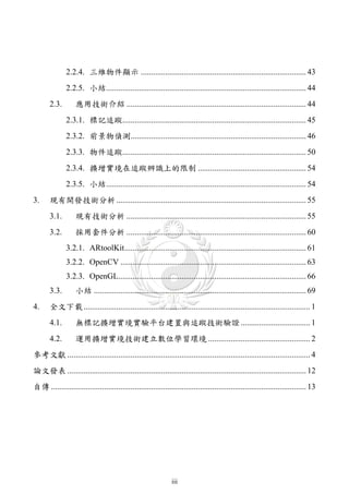
![圖 2.1 頭戴顯示器[2]。
對許多人來說,或許是第一次聽到擴增實境這一個名詞,然而另外一個名
詞-「虛擬實境(Virtual Reality)」,相信一定不會感到陌生。在 1994 年Paul
Milgram和Fumio Kishino等人[5],提出了「真實-虛擬連續性(Reality–Virtuality
Continuum)」的理論,他們將真實環境和虛擬環境分別作為連續性的兩端,如圖
。其中靠
2.2所示,然而位於兩邊端點之間的被稱為「混合實境(Mixed Reality)」
近 真 實 環 境 的 是 擴 增 實 境 , 靠 近 虛 擬 環 境 的 則 是 擴 增 虛 境 (Augmented
Virtuality)。
圖 2.2 真實-虛擬連續性[5]。
以融入的程度來區分,虛擬實境與擴增實境仍有差異存在的,擴增實境提
供一個複合式之景觀,讓使用者所見之場景為真假兼具;而虛擬實境則是一種
6](https://image.slidesharecdn.com/markerlessaugmentedrealityplatformdesignandverificationoftrackingtechnologies-110726224337-phpapp01/85/slide-18-320.jpg)
![完全融入之環境(Totally Immersive Environment),讓使用者的視覺、聽覺與知覺
等,則必須完全在虛擬實境系統的控制中,系統必須模擬出一個涵蓋使用者各
種輸入處理之完全人造世界,這是一個非常有挑戰性的議題。
在 1997 年 Ronald Azuma[6] 提 出 了 擴 增 實 境 是 由 虛 擬 環 境 ( Virtual
。所謂的虛擬環境技
Environments, VE)所變化而來的(或者稱呼為虛擬實境)
術是讓使用者完全沉浸在一個合成環境中,使用者無法看到在位於他周圍的真
實世界;而擴增實境則在真實世界中複合疊加虛擬物件,換句話說,擴增實境
允許使用者看到真實的世界。為此Azuma下了一個更明確的定義,它必須同時
擁有下面三個特性:一是結合真實與虛擬(Combines real and virtual)、二是即時
性的互動(Interactive in real time)、三是資訊的呈現必需在三度空間內(Registered
in 3-D)。
2.1.2. 擴增實境的原理
有別於虛擬實境技術,是以假想空間將現實畫面完整重現於電腦畫面;而
擴增實境技術,則是將實際資訊以虛擬方式重疊至現實環境,藉由將虛擬資訊
融入真實環境以提高生活之便利。
在 2005 年Oliver Bimber和Ramesh Raskar的「Spatial Augmented Reality
Merging Real and Virtual Worlds」著作一書中提出了擴增實境的基礎架構[51],
如圖 2.3中所示 第一層的追蹤(Tracking)與定位(Registration) 顯示技術(Display
。 、
Technology)和三維立體繪圖(Rendering)為基礎部分。第二層為人機互動機制
(Interaction devices and techniques)、展示(Presentation)和創作(Authoring),如
果與虛擬實境比較的話,目前虛擬實境技術則較為成熟。因為虛擬實境的大部
分研究已經邁向此階段,而目前擴增實境則依然停留在基礎階段。第三層為應
用程序,透過擴增實境之相關技術,有效的將結果呈現在使用者面前。第四層
7](https://image.slidesharecdn.com/markerlessaugmentedrealityplatformdesignandverificationoftrackingtechnologies-110726224337-phpapp01/85/slide-19-320.jpg)
![則是終端使用者。
User
Application
Interaction Devices and Techniques Presentation Authoring
Tracking and Registration Display Technology Rendering
圖 2.3 擴增實境的基礎架構[51]。
關於追蹤定位技術,依據不同的應用範圍,將會採用不同的追蹤定位技術。
以追蹤技術來說,有計算機視覺、電磁裝置、全球地位系統(Global Positioning
System, GPS)、羅盤、迴轉儀(Gyroscope)等技術;對於影像處理技術來說,利
用 計 算 機 視 覺 來 進 行 追 蹤 是 一 個 值 得 發 展 的 一 個 領 域 。 視 覺 追 蹤 (Visual
Tracking)又可以區分標記與無標記兩類。至於定位技術,主要是將追蹤資訊準
確地呈現在裝置上。例如在擴增實境的應用中,將虛擬物件準確的取代真實影
像中的被追蹤物件。
此外有別於既有的追蹤與定位,視覺追蹤技術採用了攝影機來當作輸入裝
置,所以額外增加校準(Calibration)這一個部分,其主要是由軟體即時地計算攝
影鏡頭的各項參數,例如視野範圍、感應位置與物件位置、歪斜率等等。所以,
以視覺追蹤技術來說,可以分為追蹤、定位與校準這三個部分。
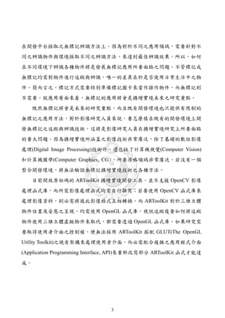
將視覺追蹤技術用於擴增實境應用,其基本運作流程分為四大部分,圖 2.4
為標記視覺追蹤運作示意圖:
(1) 從攝影機讀取標記物件之影像。
(2) 分析追蹤物件之角度及位置,進行位置及姿態的估算。
(3) 載入三維立體虛擬物件,並進行疊加作業。
8](https://image.slidesharecdn.com/markerlessaugmentedrealityplatformdesignandverificationoftrackingtechnologies-110726224337-phpapp01/85/slide-20-320.jpg)
![理的方式,對系統效能及現場光源變化的反應程度各有不同。目前廣泛被使用
的基準追蹤(Fiducial Base Tracking)系統是由Kato等人[7]發展出來並應用於
ARToolKit,它提供相對可靠穩定建置應用的函式庫,圖 2.5為ARToolKit[72]
常用之標記。
圖 2.5 ARToolKit標記範例[72]。
標記擴增實境系統必須經由特定標記、圖樣提供系統辨識及定位,除了函
式庫所包含之標記外,也可以依據需求自行設計標記圖示,如圖 2.6所示。為
了能夠準確的追蹤定位,ARToolKit[72]官方建議圖標設計的原則如下:
(1) 在黑色正方形中間包含一個白色正方形,可參考套件所附之 blankPatt.gif
圖檔。
(2) 白色正方形內之圖案採用黑色、白色或彩色來設計。
(3) 白色正方形內之細部圖案最好為非對稱設計。
10](https://image.slidesharecdn.com/markerlessaugmentedrealityplatformdesignandverificationoftrackingtechnologies-110726224337-phpapp01/85/slide-22-320.jpg)
![圖 2.6 自行設計可用於 ARToolKit 之標記。
不同的開發套件之標記也採用不同的設計方式,如圖 2.7為ARTag[78]官方
網站的應用介紹,可以從圖中看到其標記設計與ARToolKit之標記不同。依據
ARToolKit[72]官方網站介紹,ARTag開發套件針對ARToolKit之標記部分進行修
改,而運作原理則與ARToolKit相同。
圖 2.7 ARTag應用實例[78]。
QR Code(Quick Response Code)為另一種常見的標記,它是二維條碼的一
種,在 1994 年由日本Denso-Wave公司發明[58]。其來自英文「Quick Response」
11](https://image.slidesharecdn.com/markerlessaugmentedrealityplatformdesignandverificationoftrackingtechnologies-110726224337-phpapp01/85/slide-23-320.jpg)
![的縮寫,即快速反應的意思,因為發明者希望QR Code可讓其內容快速被解碼。
QR碼目前廣泛應用於日本,並為目前日本最流行的二維空間條碼。它在水平與
垂直方向中都包含有意義之資訊,所以比普通條碼可儲存更多資料,亦無需像
普通條碼般在掃描時需直線對準掃描器。
圖 2.8為透過QR-Code Generator[59]所產生之QR Code圖像,呈正方形,只
有黑白兩色。在 3 個角落,印有較小,像「回」字的正方圖案,主要用於幫助
解碼軟體定位,使用者不需要對準,無論以任何角度掃描,資料仍可正確被讀
取。也因為辨識率高,所以有學者用它取代原本的標記,將其運用在擴增實境
的應用上。Kan等人[8]在 2009 年就將QR Code結合擴增實境應用於商品之展
示,如圖 2.9所示。
圖 2.8 透過QR-Code Generator產生之範例[59]。
12](https://image.slidesharecdn.com/markerlessaugmentedrealityplatformdesignandverificationoftrackingtechnologies-110726224337-phpapp01/85/slide-24-320.jpg)
![圖 2.9 QR Code結合擴增實境之應用[8]。
目前智慧型手機在擴增實境上的應用有越來越廣泛之趨勢,QR Code 搭配
手機的應用也是行之有年,相信未來會有更多結合 QR Code 在擴增實境之相關
應用被提出;不過,這只是整個擴增實境應用的一小部分,而有更大的應用將
會在無標記的應用領域上。
2.1.3.2. 無標記系統
有別於標記系統,無標記系統採用自然特徵追蹤(Nature Feature Tracking)
當作基礎技術,不需採用特定之標記、圖樣來進行追蹤辨識與定位,使用者可
以依據喜好自行設計圖樣或使用真實物件來達成追蹤辨識與定位之目的。在
2004 年Gordon等人[9]使用不變的影像特徵來進行識別追蹤。Yuan等人[11]在
2005 年提出一個廣義的擴增實境定位方法,運用此概念即可結合自然特徵追蹤
方法來進行定位。關於無標記之特徵點辨識,常採用物件的紋理、顏色、輪廓
等來當作辨識之條件。
德國Metaio公司之擴增實境開發套件Unifeye,在其白皮書中就採用圖形辨
13](https://image.slidesharecdn.com/markerlessaugmentedrealityplatformdesignandverificationoftrackingtechnologies-110726224337-phpapp01/85/slide-25-320.jpg)
![識來當作無標記應用之範例說明,如圖 2.10中所示,系統辨識出書中的圖形,
立即在顯示器上顯示相對應的三維虛擬影像。至於實際運用,其並未侷限於平
面之圖形,亦可採用實體物件當作追蹤辨識之特徵,只要有足夠之特徵可以供
辨識即可。圖 2.11為樂高採用Unifeye所設計之擴增實境展示機,利用辨識相關
圖示標籤與消費者即時互動,來將玩具之三維物件呈現在銷售機螢幕上。
圖 2.10 無標記擴增實境應用[83]。
圖 2.11 樂高擴增實境展示機[82]。
關於無標記的應用,通常需要伴隨著事前的辨識訓練,也就是針對不同之
14](https://image.slidesharecdn.com/markerlessaugmentedrealityplatformdesignandverificationoftrackingtechnologies-110726224337-phpapp01/85/slide-26-320.jpg)
![應用,需要不同的訓練,才能夠讓系統如預期般的運作;另外,對於不同之實
體物件,也需採用不同的辨識方法,如此才能達到最佳辨識效果。雖然無標記
之辨識能力不如標記來的成熟,然而其確有不可取代性。因為採用現實生活中
之實體物件當作辨識物件,這樣就不必拘泥於既有的標記圖示,而其應用也會
變的比較廣泛。不過目前之開發套件,只針對該套件提出之應用做有限度的支
援;也因為如此,才需要更多的追蹤辨識技術加入擴增實境之領域。
2.1.4. 擴增實境的呈現
擴增實境的呈現技術也是引導整個技術發展的很大原因之一,虛擬實境往
往需要搭配全套設備一起使用,所以能應用的範圍給侷限住了;而擴增實境則
希望將場景移往日常生活之中,所以要有輕便的相關設備才能得到大眾的青
睞。從顯示方式的型態來看,1994 年Milgram等人[5]將擴增實境顯示器分為
See-Through與Monitor-Based兩大類,並在混和實境中探討各種顯示概念;
Vallino(1998) [12]依據此概念將擴增實境之影像呈現方式分為三類:
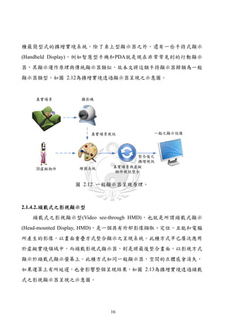
(1) 一般顯示器之顯示(Monitor-based augmented reality display)。
(2) 頭戴式之影視顯示(Video see-through augmented reality display)。
(3) 頭戴式之光學投射顯示(Optical see-through augmented reality display)。
本文參考Vallino [12]之概念重新繪製圖 2.12~圖 2.15,這三類顯示器是目
前已經成熟之技術。除此之外,目前亦有許多新式顯示器在開發,若將其運用
在擴增實境應用上,對於擴增實境之推展有很大幫助,故本文亦介紹未來顯示
器之發展。
2.1.4.1. 一般之顯示器顯示型
以顯示器呈現,是將所有場景與虛擬物件採用顯示器方式來呈現,這是一
15](https://image.slidesharecdn.com/markerlessaugmentedrealityplatformdesignandverificationoftrackingtechnologies-110726224337-phpapp01/85/slide-27-320.jpg)

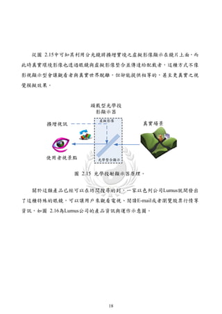
![圖 2.16 Lumus公司的產品資訊[60]。
2.1.4.4. 未來顯示器之發展
在 1977 年推出的「星際大戰(Star Wars)」系列電影中,莉亞公主發出的信
息,被以全息圖(Hologram)的形式發送給絶地武士,如圖 2.17為星際大戰中之
場景畫面。在「回到未來 2」電影中,也有呈現這種投影技術之情節。簡單地
說,全息圖就是讓影像直接出現在空氣裡面,不管是二維還是三維影像都將栩
栩如生地出現在空氣中呈現。對於這樣的技術,不管對於過去甚至現在來說,
都是具有挑戰性,若在此技術成熟並普及在生活中後,擴增實境之應用也將更
生活化。
19](https://image.slidesharecdn.com/markerlessaugmentedrealityplatformdesignandverificationoftrackingtechnologies-110726224337-phpapp01/85/slide-31-320.jpg)
![圖 2.17 第一部星際大戰中的場景[61]。
日 本 日 立 公 司 人 類 交 互 作 用 實 驗 室 (Hitachi Human Interaction
Laboratory)[62]就有從事這方面的開發,如圖 2.18所示。其命名為Transpost,
這套系統可以將二維圖像轉變成立體圖像,它能使人不用戴特殊眼鏡就能看到
立體圖像,就有如星際大戰中的全息通訊系統。
圖 2.18 日立的Transpost系統[62]。
日本Aircord實驗室[63]也利用iPAD展示他們研發的N-3D立體顯示器,如圖
2.19所示,用一個金字塔形的銀幕膠片來投射影像內容,讓人們直接使用肉眼
20](https://image.slidesharecdn.com/markerlessaugmentedrealityplatformdesignandverificationoftrackingtechnologies-110726224337-phpapp01/85/slide-32-320.jpg)
![從各個方向觀看立體影像。首先在iPad的銀幕上會顯示出多個動畫畫面,每一
個畫面可以投射到透明罩的一個斜面上,經過光線的折射後,多個畫面將會在
透明罩的中心部位整合,然後再經過多次的反射後,使用者就能使用肉眼看到
這種立體畫面。此外,該系統不僅可在iPad上運作,亦可以採用投影設備來進
行展示。
圖 2.19 N-3D立體顯示器[63]。
美國麻省理工學院的研究生Chad Dyne[64],也發明空氣投影和互動技術,
並將其命名為Heliodisplay,它可以在氣流形成的牆上投影出具有交互功能的圖
像,此技術來源是海市蜃樓的原理,將圖像投射在水蒸氣上,由於分子震動不
均衡,可以形成層次和立體感很強的圖像。目前可以在IO2 Technology[64]中找
到這個產品的相關資訊,如圖 2.20為實際展示影片畫面。
21](https://image.slidesharecdn.com/markerlessaugmentedrealityplatformdesignandverificationoftrackingtechnologies-110726224337-phpapp01/85/slide-33-320.jpg)
![圖 2.20 Heliodisplay空氣投影[64]。
除了上述所介紹的顯示器之外,目前還有眾多之顯示方式被提出,例如華
盛頓大學(University of Washington)的Babak Parviz[65]在 2009 年時便在北京的
BioCas研討會上展示一款可代替LED電腦螢幕、能將影像直接投射到視網膜上
之隱形眼鏡,如圖 2.21中所示,左圖為隱形眼鏡電路與鏡頭,右圖為配戴在兔
子眼睛上後的情景。不管這些新新的顯示技術目前的是否已經成熟,相信未來
都會影響著擴增實境之發展。
圖 2.21 隱形眼鏡鏡頭[65]。
2.1.5. 擴增實境的應用
眾所皆知,擴增實境的應用,正如火如荼地在各個領域中展開。可將其應
22](https://image.slidesharecdn.com/markerlessaugmentedrealityplatformdesignandverificationoftrackingtechnologies-110726224337-phpapp01/85/slide-34-320.jpg)
![用在教育、醫學、遊戲、軍事、維修、商業等各種領域中,而各個領域的相關
文獻也都不斷被提及,甚至有些已經朝向商品化階段。
魔 法 書 為 Mark 等 人 [13] 在 華 盛 頓 大 學 之 人 機 介 面 科 技 實 驗 室 (Human
Interface Technology Laboratory)所進行之研究計畫。如圖 2.22所示,它是使用
手持式之擴增實境顯示(Hand Held Display, HHD)方式,將虛擬物件與真實的書
整合呈現,在人機介面操作上,則是以書籍、電腦搭配手持式顯示器,所整合
之真實與虛擬混成環境,作為整個系統之溝通介面。若使用者並未使用任何擴
增實境之嵌入式科技,這本魔法書就如同一般書籍一樣,使用者可以直接進行
閱讀;若不同的使用者,在不同的角度分別使用手持式顯示器觀看書籍,在書
籍的上方,則會出現配合書籍內容的虛擬主角、虛擬物件與虛擬場景,而且會
隨著觀看角度不同,而改變呈現效果,從傳統實體書籍搖身一變成為立體多媒
體書籍。當使用者翻閱不同畫面時,不同的場景與情節,將搭配書籍內容以即
時改變方式,呈現在觀賞者的眼前。
圖 2.22 魔法書的應用[13]。
在教育學習上,可將其應用於數位學習,或者互動的幼教教材,甚至將其
應用在以往較抽象的物理化學原理上。2007 年Bötschi等人[14]在有機化學的教
學上,就針對採用擴增化學(Augmented Chemistry, AC)這一套有形的使用者介
面與傳統BSM模型(Ball-and-Stick Model, BSM)這兩種教學方式做一比較。如圖
23](https://image.slidesharecdn.com/markerlessaugmentedrealityplatformdesignandverificationoftrackingtechnologies-110726224337-phpapp01/85/slide-35-320.jpg)
![2.23所示,圖(a)為使用背投影方式呈現擴增化學使用介面之畫面,右方圖示為
使用右手操作來旋轉立方體,而在標記上方可看到分子結構;圖(b)為傳統BSM
模型的教學設備,右方圖示為傳統BSM模型實際組合的分子結構。在 2002 年
Shelton等人[15]將其應用在地球與太陽之運作教學上,如圖 2.24所示,左圖為
使用者配戴頭戴顯示器操作畫面,右圖為使用者觀看頭戴顯示器之顯示畫面。
這些教學方式可以讓學生有身歷其境的感覺,可以有效的提升學生學習興趣。
(a)
(b)
圖 2.23 化學教學應用[14]:(a)擴增化學;(b)BSM模型。
圖 2.24 太陽與地球之運轉[15]。
24](https://image.slidesharecdn.com/markerlessaugmentedrealityplatformdesignandverificationoftrackingtechnologies-110726224337-phpapp01/85/slide-36-320.jpg)
![醫學科技不斷的提升,相信對於全體人民來說,這是一個很大的福音。除
了外科手術應用上,對於沒有臨床經驗的醫護人員,亦可透過擴增實境的幫忙,
來提升其操作上之相關經驗。Fischer等人[18]提出採用現有的IGS(Image Guided
Surgery)醫學設備,結合擴增實境技術來完成擴增實境在醫學手術上之應用。其
利用攝影機追蹤標記,並透過醫療數位影像傳輸協定(Digital Imaging and
Communications in Medicine, DICOM)來取得電腦斷層掃描(X-ray Computed
Tomography, CT)或核磁共振攝影(Magnetic Resonance Imaging, MRI)所產生之
影像資料,最後透過擴增實境繪圖技術,將三維影像呈現在醫療設備上,如圖
2.25為IGS結合擴增實境技術顯示MRI掃瞄之心臟三維影像。
圖 2.25 心室模型[18]。
在設備的維護上,寶馬汽車(BMW)便在汽車維修上應用擴增實境的技術。
維修人員只要帶上一幅具有顯示功能的眼鏡,配合聲控功能,當維修人員對着
汽車引擎時,眼鏡便會顯示出相關配件的位置及操作程序。不但省卻查閱操作
手册的時間,亦減少出錯的機會。而Steve Henderson和Steve Feiner[19]指出,在
複雜的維修作業中 透過擴增實境技術的幫助可以減少時間和精力的浪費 如圖
, 。
2.26所示,透過擴增實境應用系統的幫助來對裝甲運兵車進行維修作業。相信
此技術對軍方或民間來說,是一個很有用的一項技術,其不但可以節省訓練上
的時間,亦可幫助維修人員迅速進入狀況。
25](https://image.slidesharecdn.com/markerlessaugmentedrealityplatformdesignandverificationoftrackingtechnologies-110726224337-phpapp01/85/slide-37-320.jpg)
![圖 2.26 裝甲運兵車維修作業[19]。
以遊戲的發展史來看,從早期挑戰人工智慧,進而發展到網路連線對戰,
這代表著人們渴望彼此的互動。Wii Sport®[66]的推出,其利用偵測玩家的行
為、力道、角度等,進而做出不同的回饋效果,這更是改變了以往玩遊戲的習
慣。若在視覺上能結合擴增實境,讓整個遊戲融入到真實環境中,相信這將再
次顛覆整個遊戲市場。日本Sony在 2009 年秋季推出適合全家大小一道同樂的
虛擬寵物遊戲EyePet™[67],透過PlayStation®Eye攝影機搭配擴增實境技術,將
EyePet融入真實環境中,讓玩家以臥房或客廳為舞台,與俏皮EyePet進行深度
互動。
圖 2.27 虛擬寵物遊戲EyePet™[67]。
26](https://image.slidesharecdn.com/markerlessaugmentedrealityplatformdesignandverificationoftrackingtechnologies-110726224337-phpapp01/85/slide-38-320.jpg)
![以往對於已經消失的歷史古蹟,只能透過既有的圖片或文字來想像古蹟昔
日的風貌,然而如果能結合擴增實境的技術,那麼可以在原遺址上,利用三維
繪圖技術,進行虛擬原貌恢復。在 2001 年Vlahakis等人[20]提出將已經毀損的
古蹟建築透過擴增實境之技術,在原址疊加古蹟原來的面貌。
(a) (b)
圖 2.28 損毀古蹟重建之應用[20]:(a)原址;(b)疊加虛擬模型之面貌。
在瀏覽博物館時,以往對於文物的介紹,只能從文字或者導覽語音來進行
瞭解,若善用擴增實境之技術,不在只能透過語音方式來瞭解文物的歷史,而
更可以透過互動方式,進行相關文物資訊的查詢與介紹,對於該文物有更深入
的瞭解。2005 年Huang [21]提出利用電腦視覺技術來輔導參觀者與展場之間的
互動,提升參觀者對展場的融入感與互動性;在博物館的應用中,利用擴增實
境之技術來顯示文物資訊以增加參觀者的融入感,如圖 2.29為利用文物展示系
統呈現之結果。
27](https://image.slidesharecdn.com/markerlessaugmentedrealityplatformdesignandverificationoftrackingtechnologies-110726224337-phpapp01/85/slide-39-320.jpg)
![圖 2.29 虛擬博物館系統[21]。
2.1.6. 小結
從上述討論可知擴增實境之發展,是經過漫長歲月之洗滌,在相關技術相
繼成熟後,才能有此佳績。未來其所能帶給人類之貢獻,是可以想像的,至於
要怎麼樣運用此技術,更是相關研究人員該探索的,相信不久之將來,一定會
有更多的探討文獻相繼提出,讓這個研究領域的技術融入生活中。
2.2. 基礎概念介紹
要處理三維電腦繪圖,就必須先瞭解座標的相關知識,想要在二維的螢幕
描繪出三維空間之物體,就必需要瞭解投影之原理。換句話說,三維物體之呈
現是使用投射的概念,將三維圖形投影成二維圖形在螢幕上顯示出來。雖然投
影成二維圖形,但為了讓此二維圖形看起來有三維的感覺,可以使用一些三維
效果讓觀看者產生三維的幻覺。
這些看似簡單的觀念,其背後都有一堆數學算式作為基礎,簡單的來看待,
就是需要在不同的座標系統間進行轉換,最後才能有一個滿意之呈現效果。
28](https://image.slidesharecdn.com/markerlessaugmentedrealityplatformdesignandverificationoftrackingtechnologies-110726224337-phpapp01/85/slide-40-320.jpg)
![2.2.1. 座標系統
對一個位置,通常需要給予一個固定單位的座標用來提供識別其位置所
做,所以不管是二維、三維都需要統一的測量與定位方式;在三維圖形處理中
將會使用多種座標系統,它們在各自的場合中有其獨特的地方,透過它們之間
的轉換,可以簡化圖形程式之開發,然而不同座標系要如何轉換,就必需深入
的去瞭解計算機圖學,常見座標系統有[53][55]:
(1) 世界座標系統(World Coordinate System, WCS)。
(2) 物體座標系統(Object Coordinate System)。
(3) 觀察座標系統(Observe Coordinate System)。
(4) 設備座標(Device Coordinates, DC) 系統與正規化設備座標 (Normalized
Device Coordinates, NDC) 系統。
(5) 螢幕座標系統(Screen Coordinate System)。
以下針對各個座標系統做一簡短介紹,首先介紹的是世界座標系統,世界
座標系統是一個獨特的座標系統,因為世界座標系統建立了描述其它座標系統
所需要的參考框架。從非技術意義上來說,世界座標系統所建立的是整個場景
的最大座標系統,其它的座標系統都是參考世界座標系統來建立的。
世界座標系統也被廣泛稱為全局座標系統或宇宙座標系統。對整個場景中
的每一個物體,它的位置和方向一般是指它在世界座標中的值,它是一個絕對
座標,不會隨者觀察者方向之變化而改變。
物體座標系統適合特定的物體相關連的座標系統,也被稱為模型座標系統
(Model Coordinate System)或局部座標系統(Local Coordinate System),對於場景
中的每一個物體都可以有自己的物體座標系統,而且其和其它物體的物體座標
29](https://image.slidesharecdn.com/markerlessaugmentedrealityplatformdesignandverificationoftrackingtechnologies-110726224337-phpapp01/85/slide-41-320.jpg)
![系統是相互獨立的。圖 2.30顯示了物體與物體座標系統的關係,而圖 2.31則顯
示了世界座標系統與物體座標系統之間的關係。
y-axis
物體
O
x-axis
z-axis 物體座標系統
圖 2.30 物體與物體座標系統[55]。
圖 2.31 世界座標系統與物體座標系統[55]。
物體座標系統在三維世界中處處存在,每一個物體發生移動或改變方向
時,和該物體相關的物體座標系統,也隨之移動或改變方向,這將大幅簡化對
30](https://image.slidesharecdn.com/markerlessaugmentedrealityplatformdesignandverificationoftrackingtechnologies-110726224337-phpapp01/85/slide-42-320.jpg)
![各個模型的控制。
觀察座標系統是與觀察者相關的座標系統,也被稱為攝影機座標系統,在
該座標系中採用右手座標系統,攝影機觀察點位於原點,X軸為右,Z軸為前,
Y軸向上,而這裡的上方,並非一定是世界座標中的上方,而是指攝影機本身
的上方,如圖 2.32所示。觀察者座標系在三維圖形處理中非常重要,它是聯繫
三維世界座標系統與二維設備座標系統的橋樑。
圖 2.32 物件與觀察者座標系統[55]。
設備座標系統是與圖形設備的物理參數有關之座標系統;而正規化座標系
統是獨立於具體物理設備的一種座標系統 其具有顯示空間和在 X 與 Y 方向上
,
都是從 0 到 1。對於每台物理設備而言,NDC 與 DC 是座標值相差一個比例因
子,它可以看成是一個抽象的圖形設備。
最後是螢幕座標系統,其為顯示器的平面座標系統,它的座標原點位於螢
幕的左上角,水平方向右為 X 軸方向,垂直向下為 Y 軸方向,以像素為單位。
任何物體的頂點座標最終都要轉化為螢幕座標系統中的座標來進行顯示。
31](https://image.slidesharecdn.com/markerlessaugmentedrealityplatformdesignandverificationoftrackingtechnologies-110726224337-phpapp01/85/slide-43-320.jpg)
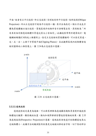
![2.2.2. 投影原理
在很久以來藝術家與建築師都試圖在解決如何用二維方法表示三維物體或
場景這樣的一個問題,而其所面臨的問題在現今圖學的設計者也同樣面臨相同
問題。而三維電腦繪圖的投影原理是一種由三維到二維的過程,利用二維座標
來表示三維空間中的位置,在電腦螢幕上的像素仍然為平面的,也就是將三維
笛卡兒座標轉換成可繪製在螢幕上的二維座標,如圖 2.33所示,為空間中之點
P投影到投影平面P’之示意圖,P點的映射是由一條穿過P點並與投影平面相交
之投影線來確定;而物體投影的結果取決於物體上一個個點進行投影所產生之
投影線間之空間關係。
圖 2.33 投影問題[56]。
2.2.2.1. 正交投影
正交投影(Orthographic Projection)是一系列用於顯示三維物體的輪廓、細節
或 精 確 測 量 結 果 的 變 換 方 法 。 通 常 又 被 稱 作 平 面 圖 (Plane) 、 截 面 圖
(Cross-section)、鳥瞰圖(Bird's-eye)或立面圖(Elevation)。在平行投影中所有的投
影線都互相平行並且有著相同的投影方向。此外,如果所有投影線都垂直於視
32](https://image.slidesharecdn.com/markerlessaugmentedrealityplatformdesignandverificationoftrackingtechnologies-110726224337-phpapp01/85/slide-44-320.jpg)
![稱為截頂錐體(Frustum)。靠近觀察區域前方的物體大小與實際大小較相近,但
靠近末端的物體投射後會縮小許多。此種投射方式為虛擬與三維立體動畫帶來
最佳的真實感。
圖 2.35 透視投射示意圖。
2.2.3. 攝影機模型
在Learning OpenCV[52]書中提及針孔攝影機模型(Pinhole Camera Model)
為最簡單之攝影機模型,其為一透視投影(Perspective Projective )的成像方式,
如圖 2.36所示。想像有一光線是從很遠的場景或很遠的物體發射過來,但其實
是來自於某一條光線。影像平面(Image Plane)是成像結果也稱為投影平面
(Projective Plane),其中圖像是被聚焦。在整個成像的過程中,所選擇之投影中
心(Projection Center)與影像平面(Image Plane)對於整個成像的結果有著決定性
影響。這些看似簡單的觀念,裡面包含著許多座標系統之轉換,接下來就做一
簡單之介紹。
34](https://image.slidesharecdn.com/markerlessaugmentedrealityplatformdesignandverificationoftrackingtechnologies-110726224337-phpapp01/85/slide-46-320.jpg)
![圖 2.36 針孔攝影機模型[52]。
在圖 2.36中可看到兩個相似三角形,利用相似三角形原理推得:
h H H
或 h f
f D D (2.1)
其中各個參數說明如下:
(1) f 是攝影機焦距。
(2) D 是攝影機到物體的距離。
(3) H 是物體實際高度。
(4) h 是 Image plane 中物體的圖像高度。
將整個應用擴展到三維空間,並將整個光學軸(Optical Axis)往下移位,其
目的在於消除負號,讓所有的計算都在光學軸之上。在基本的針孔攝影機模型
中,將投影中心放置在歐氏座標系統(Euclidean Coordinate)的原點,並將影像平
面放置在Z 軸上距離原點為 f 的位置。在此針孔攝影機模型之下,一個在三維
空間的點 Q (X, Y, Z) T ,其投影至二維影像上的q點,其中 q ( x screen , y screen ) 。也就
是由投影中心與三維座標點Q之連線和成像平面之交點,如圖 2.37所示。
35](https://image.slidesharecdn.com/markerlessaugmentedrealityplatformdesignandverificationoftrackingtechnologies-110726224337-phpapp01/85/slide-47-320.jpg)
![圖 2.37 針孔攝影機模型之投影關係圖[52]。
將座標為 ( X , Y , Z ) 之物理點 Q 映射到投影平面上座標為 ( x screen , y screen ) 之點q的
過程稱為投影變換(Projective Transform),而齊次座標可把維度為n的投影空間
上的點用(n+1)維向量表示;換句話說,二維平面投影空間,可以使用一個三維
向量 q (q1 , q 2 , q 3 ) 來表示該平面的點,如公式(2.2)所示,其中λ為一比例係數,
因為投影空間上的所有比例不變,因此可以透過除以 q 3 來計算實際之像素座標
值。
xq q1
y q
q 2 (2.2)
f
q3
藉由前面所提之相似三角形的原理,可推算出三維座標點 Q (X, Y, Z) T 投影
X Y
到影像平面上之二維點 q ( f , f ) T ,故可獲得從三維空間投影至二維空間之
Z Z
映射關係。其中的投影中心又稱之為攝影機中心(Camera Center)或光學中心
(Optical Center),Z軸稱之為主軸(Principal Axis),而主軸與影像平面的交點稱之
為主點(Principal Point)。對於大部分影像呈現採用矩形而非正方形,故針對X軸
與Y軸分別定義兩個不同之焦距 f x 與 f y ,透過公式 (2.1)推得投影平面上座標:
36](https://image.slidesharecdn.com/markerlessaugmentedrealityplatformdesignandverificationoftrackingtechnologies-110726224337-phpapp01/85/slide-48-320.jpg)
![q c K I | 0Qc (2.13)
一般而言,在真實空間下的三維座標皆以世界座標系統來表示,而非以相
機座標系統(Camera Coordinate),所以在這之間還有一個座標轉換的動作,在二
個座標系統之間的關係,可用旋轉(Rotation)與位移(Translation)來轉換,如圖
2.39所示。
( R, t ) X w
Y
Qw w
Zw
1
x
q
y
圖 2.39 世界座標系統 Q w 與攝影機座標系統 Q c 之轉換圖[52]。
假設 Q 為一在世界座標系統下之三維座標點,齊次座標點以
Q w (X w , Yw , Z w ,1) T 表示;而 Q c 表示為在相機座標系統下之相對三維座標點,則
Q w 與 Q c 之關係可經由一位移矩陣T與一旋轉矩陣R來表示,其中位移向量t表示
攝影機在世界座標系統之位置,而R表示攝影機之方向,故將之表示成公式
40](https://image.slidesharecdn.com/markerlessaugmentedrealityplatformdesignandverificationoftrackingtechnologies-110726224337-phpapp01/85/slide-52-320.jpg)
![ fx 0 cx
K 0
fy cy
(2.16)
0
0 1
其中, f x fq x , f y fq y 。另外,在感光耦合元件相機中,在物理意義上的
像素也不一定是矩形,而 X 軸與 Y 軸有一歪斜的參數 s ,最後將整個完整的
感光耦合元件相機校正矩陣表示為:
fx s cx
K 0
fy cy
(2.17)
0
0 1
因此整個呈現過程是經過多重的座標系統轉換,若不考慮過多的參數,則
針孔攝影機模型之投影可用公式(2.18)表示 對於整個攝影機之參數矩陣計算採
。
用Heikkila和Silven[22]的方法,這也是OpenCV內部所採用之方法。
1 0 0 0
R Rt
q K 0 1 0 0 T Qw K R | Rt Qw MQw
1
0 (2.18)
0 0 1 0
重新整理各個參數說明如下:
(1) 二維影像上的 q 點。
(2) 三維座標點 Q。
(3) 三維齊次座標點 Qw。
(4) 三維攝影機座標點 Qc。
(5) M 稱為攝影機投影矩陣。
(6) K 稱為攝影機校正矩陣。
42](https://image.slidesharecdn.com/markerlessaugmentedrealityplatformdesignandverificationoftrackingtechnologies-110726224337-phpapp01/85/slide-54-320.jpg)
![(7) R 稱為旋轉矩陣。
(8) T 稱為位移矩陣。
(9) t 稱為位移向量。
2.2.4. 三維物件顯示
上一節介紹了針孔攝影機模型的運作原理,在三維電腦繪圖領域中,也運
用類似的觀念,只不過其需要經過更多的座標系統轉換,這樣才能使物體以適
合的位置、大小與方向顯示出來,依據OpenGL Programming Guide [53] 與
Computer Graphics Using OpenGL[54]書籍整理座標系統轉換流程如圖 2.40所
示。三維虛擬物件要有三維空間呈現之效果,其必須將三維物件透過相關的幾
何座標轉換轉成人類所接受之座標,再利用投影變換矩陣來將影像轉換成二維
影像,除此之外還需要仿造人類的視野來決定哪些影像將呈現在顯示設備上,
除此之外,面對不同的顯示設備還有不同設備間之座標轉換要處理,整個詳細
流程就不在此討論。
圖 2.40 三維虛擬物件呈現流程。
在擴增實境的應用中,要將三維虛擬物件融入真實環境之中,首先必須將
三維立體物件仿造攝影機擷取影像的原理來運作,最後利用三維繪圖技術將真
實環境與三維立體虛擬物件做疊加的動作,如此才能達到將虛擬物件融入真實
環境之中。
43](https://image.slidesharecdn.com/markerlessaugmentedrealityplatformdesignandverificationoftrackingtechnologies-110726224337-phpapp01/85/slide-55-320.jpg)

![一簡單之介紹,再來則介紹追蹤所需要之相關背景技術。
2.3.1. 標記追蹤
目前廣泛被使用的基準追蹤系統是由Kato 等人[7]發展出來並應用於
ARToolKit中,如圖 2.41所示,其透過座標轉換將標記座標轉換成攝影機座標,
然後依據門檻值取得標記矩形之四條線段,接著偵測標記內之圖案並找到具體
的對應識別ID,接著將標記位置透過向量矩陣轉換算出三維立體虛擬物件之位
置,然後載入圖標識別碼對應之三維立體虛擬物件,最後在標記位置上繪製虛
擬物件,運作示意圖如圖 2.42所示。
Yc
Camera Screen
Coordinates Camera Coordinates
Oc
Xc
xc
yc ( xc , yc )
Zc
Marker
Marker Coordinates
Ym Xm (Xm,Ym,Zm)
Zm
圖 2.41 標記座標與攝影機座標關係圖[7]。
45](https://image.slidesharecdn.com/markerlessaugmentedrealityplatformdesignandverificationoftrackingtechnologies-110726224337-phpapp01/85/slide-57-320.jpg)
![圖 2.42 ARToolKit 之標記追蹤定位流程。
2.3.2. 前景物偵測
除了影像幾何座標轉換以及繪製虛擬物件之相關技術外,追蹤技術亦是擴
增實境中不可或缺的重要關鍵技術之一,然而在影像處理研究領域裡,視覺追
蹤也並非是一塊新的研究領域,不過也並非既有的所有視覺追蹤都能夠運用於
擴增實境中。
在物件追蹤之前,首先必須能夠區分影像中的前景與背景,根據運動偵測
技 術 的 不 同 , 常 見 的 移 動 物 體 偵 測 追 蹤 方法 有 三 類 , 分 別 是 背 景 相 減 法
(Background Subtraction)、時序差異法(Temporal Differencing)與光流法(Optical
Flow Method)[23]。
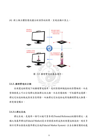
2.3.2.1. 背景影像相減法
背景影像相減法為目前在視覺監測應用上最廣泛使用的運動偵測方法,計
算公式如(2.19)所示,其基本運作原理是先用一段時間建立一個初步的背景模
46](https://image.slidesharecdn.com/markerlessaugmentedrealityplatformdesignandverificationoftrackingtechnologies-110726224337-phpapp01/85/slide-58-320.jpg)
![型。然後,使用目前的圖像中減去背景圖片來偵測移動像素。其中影像片段中
固定不變的部份視作背景,再將每一畫格上的像素與背景影像進行相減後得到
差異強度影像,若差異大於給定之門檻值,則視該點為移動像素或稱之為前景,
但它對不斷的明暗變化和移動的攝影機處理效果不彰。
I ( x, y ), if I k ( x, y ) Bk ( x, y ) Td
Fk ( x, y ) k (2.19)
0, Otherwise
其中 Fk ( x, y ) 代表第 k 個畫格時,前景影像 Fk 上點 ( x, y) 的灰階值,灰階值等
於 0 就代表該點屬於背景; I k 為第 k 個畫格的影像; Bk 為第 k 的畫格時的背
景影像; Td 為差異強度門檻值。
背景影像相減法最為關鍵之地方在於一開始如何從影像片段中擷取出背
景,目前也已經有許多不同的方法被提出,最常見的有Longa等人[24]的採取訓
練片段進行平均之平均法以及Lai等人[25]的統計每個像素上灰階值出現頻率之
投票法。
2.3.2.2. 時序差異法
時序相減法最大的優點是不必預先產生背景影像,其基本運作方式是將連
續影像中的前後兩個畫格直接相減後得到差異強度影像,再配合門檻值分離出
前景影像,如公式(2.20)所示:
I ( x, y ), if I k ( x, y ) I k 1 ( x, y ) Td
Fk ( x, y ) k (2.20)
0, Otherwise
其中 Fk ( x, y ) 代表第 k 個畫格時,前景影像 Fk 上點 ( x, y ) 的灰階值,灰階值
47](https://image.slidesharecdn.com/markerlessaugmentedrealityplatformdesignandverificationoftrackingtechnologies-110726224337-phpapp01/85/slide-59-320.jpg)
![等於 0 就代表該點屬於背景; I k 是第 k 個畫格的影像;Td 為差異強度門檻值。
由於時序相減法不需要使用到背景影像,適合在背景光影變化幅度較大的
情況下使用,但是對於偵測物體的形狀和位置也有較大的誤差。
2.3.2.3. 光流法
當眼睛觀察運動物體時,物體的景像在眼睛之視網膜上形成一系列連續變
化的圖像,這一系列連續變化的資訊不斷「流過」視網膜(即圖像平面)
,好像
一種光的「流」
,故稱之為光流。光流表達了圖像之變化,由於它包含了目標運
動的資訊,因此可被觀察者用來確定目標的運動情況。
光流法在模式識別、計算機視覺以及其他圖像處理應用中非常有用,它與
運動檢測以及運動估計緊密相關。其定義為在連續的影像平面上,各個像素之
亮度梯度。其原理是利用連續影像中各像素的亮度變化找出影像中的光流場
(Optical Flow Field),再藉光流場估計移動物體的運動向量後進行特徵匹配。
光流與影像流最大的差別在於,當物體在空間中產生位移,連續的影像平
面上會有影像流以及光流的發生。影像流是因為物體與攝影機之間的相對移動
所造成的,光流則是由於物體的相對移動或是環境的亮度梯度改變而產生。
廣義的說,光流法就是指偵測光線強弱改變之演算法,也就是以影像梯度
為匹配或追蹤基礎之演算法。最常被提及的兩種光流法,其中第一種由Lucas,
B.D.與Kanade, T. [26]於 1981 年所發表的方法,它以計算簡單、快速且經過多
年普遍應用,此法稱為Lucas–Kanade Optical Flow Method,簡稱LK光流法。另
一種則由Horn, B.K.P.與Schunck, B.G.[27]於 1981 年所發表的Horn–Schunck
Method,簡稱HS光流法。在OpenCV函數庫中,其針對LK光流法分別實現了金
字塔與非金字塔的LK稠密光流演算法;同樣的OpenCV亦提供HS光流法之演算
法函式庫。
48](https://image.slidesharecdn.com/markerlessaugmentedrealityplatformdesignandverificationoftrackingtechnologies-110726224337-phpapp01/85/slide-60-320.jpg)
![在移動物體偵測追蹤方法中,光流法的優勢在於不需建立背景,因此適用
於拍攝平台也會有運動的情況;然而光流法的計算方式複雜,運算量大,而且
對於場景中的雜訊非常敏感,往往需要額外搭配專業之硬體設備來進行即時運
算,故對於沒有強力運算能力之平台比較不適合。除此之外光流法也非能在各
個環境中應用,下面整理了可能不適合的環境與可能會遭遇的問題[49]:
(1) 光流法可能不適用之環境:
a. 沒有灰值梯度變化的物體。
b. 光源移動造成所有物體皆產生光流。
(a) 在所有物體靜止的房間之內,理論上所有特徵皆無光流產生,但若
此時光源產生改變(移動、亮度、照射方向、色溫等),在改變的
瞬間所有受光源照射的物體皆產生光流,因此會造成錯誤的光流向
量。
(b) 如果物體在空間中靜止不動,但環境的光源發生改變時,由於物體
與攝影機之間沒有相對移動存在,自然也就不會有影像流的發生。
(c) 但環境光源的變動依然會使影像平面的亮度梯度發生改變,此時有
光流值的產生。也就是說當物體靜止,但環境光源產生變化時,影
像流為零,但光流值並不為零。
c. 已經維持在穩定旋轉狀態且無梯度變化的物體 例如已經維持穩定等速
。
旋轉的電扇,此時扇葉已狀似一個圓形的圖形,故不產生光流。
(2) 光流法可能產生問題之狀況:
a. 遮蔽(Occlusion)問題:在進入遮蔽區與脫離遮蔽區的光流很可能產生錯
誤向量。
b. 視野(Aperture)問題:若特徵的移動並未涵蓋在匹配的範圍之內,則向
量會指向視野範圍內最可能的位置,但並非正確。
49](https://image.slidesharecdn.com/markerlessaugmentedrealityplatformdesignandverificationoftrackingtechnologies-110726224337-phpapp01/85/slide-61-320.jpg)
![2.3.3. 物件追蹤
一般對影像之處理與分析,首先是利用物件追蹤(Object Tracking)的技術來
追蹤動態物體,一旦追蹤到物體,就可以做進一步的肢體動作分析。而目前的
物體追蹤是透過比對連續影像間物體的相似度來完成,於是物體特徵的擷取,
相似程度的判別,目標物的搜尋,都涵蓋在此議題中。目前物體追蹤的方法可
概分成四類[23][28]:區域式追蹤 (Region-Based Tracking)、主動式輪廓追蹤
(Active Contour-Based Tracking)、特徵追蹤(Feature-Based Tracking)、以及模型
追蹤(Model-Based Tracking)。
2.3.3.1. 區域式追蹤
假設影像變動的區域即為目標物之位置 藉由偵測這些變動區域之位置來
,
追蹤目標物。通常利用目前影像與背景相減或者利用相鄰兩張影像間之差異來
偵測出變化區域,然後再進一步的建立規則來做篩選、合併或分割。
此方法之缺點在於無法處理物體合併之問題,以取得物體之三維動作,且
對於雜亂有變動之背景亦不適用。
2.3.3.2. 主動式輪廓追蹤
主動式輪廓追蹤其方法是使用輪廓線(Contour)來描述移動的物體,並利用
輪廓線之改變來進行追蹤,如Paragios等人[29]就利用這樣的方法來進行移動物
件偵測。此方法的好處在於更有效率,且降低了複雜度,由於輪廓線是封閉曲
線,即使物體交錯,也較容易解決。但其缺點仍然是缺乏三維的資訊,無法進
行三度空間上的追蹤,且此演算法的追蹤效果對於初步輪廓的偵測或選取非常
敏感,故較難用於全自動的偵測追蹤系統。圖 2.43採用主動式輪廓追蹤在高速
公路上的偵測情形,從圖中可看出輪廓逐次縮小,最後達成追蹤之目的。
50](https://image.slidesharecdn.com/markerlessaugmentedrealityplatformdesignandverificationoftrackingtechnologies-110726224337-phpapp01/85/slide-62-320.jpg)
![圖 2.43 移動車輛輪廓偵測[29]。
2.3.3.3. 特徵追蹤
特徵追蹤是利用物體的特徵來進行追蹤,首先針對要追蹤的物體擷取特
徵,這些特徵可分為三種:整體性特徵(Global Feature Based),如重心、周長、
面積與顏色等;局部性特徵(Local Feature Based),如線段、曲線段與頂點等;
相依圖形特徵(Dependence Graph Based),如特徵間的結構變化等。當影像中目
標物的低階特徵擷取出後,即可匯集成更高階的特徵資訊,利用比對連續影像
間之高階特徵來追蹤該物體。
除了相依圖形特徵方法外,其餘兩種方法可以用來即時追蹤多個移動物
體,利用運動特徵、局部特徵或相依的結構特徵來解決物體交錯的問題,但是
使用運動特徵的方法穩定性不高,而使用局部特徵的方法則比較耗時費力。此
演算法的另一缺點是,用二維影像對物體的辨識度並不高,且通常無法還原出
物體的三維資訊。
若 考 慮 良 好 的 辨 識 效 果 , Lowe[31] 所 發 表 的 尺 度 不 變 特 徵 轉 換
(Scale-invariant feature transform, SIFT)是一個選擇,它在空間尺度中尋找極值
51](https://image.slidesharecdn.com/markerlessaugmentedrealityplatformdesignandverificationoftrackingtechnologies-110726224337-phpapp01/85/slide-63-320.jpg)
![點,並提取出其位置、尺度、旋轉不變數,可用來偵測與描述影像中的局部性
特徵且有很好的辨識效果,不過辨識時間需要比較久。
為了改善SIFT搜尋速度慢,Bay等人[33]提出SURF (Speeded-Up Robust
Features),雖然找出之特徵點不及SIFT演算法來的多,不過其搜尋速度卻比
SURF快上許多,也是目前常用之搜尋特徵點演算法。除此之外,針對SIFT提
出 改 善 的 尚 有 Ke 等 人 [34] 所 提 出 的 PCA-SIFT(Principal Components
Analysis-SIFT)與Morel 等人[35]提出的Affine-SIFT (ASIFT)等方法。
在實際的應用,除了採用改良的方法來縮短辨識時間,亦可利用硬體平台
來加快演算速度,例如採用多核心之中央處理器或圖形處理器來進行運算處
理,而SiftGPU[69]與GPU SURF[71]則分別是透過圖形處理器來完成SIFT與
SURF演算法之例子。
2.3.3.4. 模型追蹤
模型追蹤的方法將會提供較精細與準確的判斷,因此需要良好的物體結構
模型,可加入物體本身之運動特性。所以,其比較不易受附近背景或其它物體
干擾之影響,也較能對抗物體間交錯問題,所以相對地運算量也比較大。通常
其追蹤的方式可分為「建立物體模型」「建立運動模型」與「預測和搜索策略」
、
三個步驟。
模型追蹤的方法與前三者方法相比,有幾項優點。因為其取得之影像即為
三維資訊,故不需要額外處理才能獲得三維資訊;並且利用先前的三維資訊,
便可整合做為判斷下一個動作之根據,故縱使物體間互相交錯,也可以準確地
進行判斷;除此之外,仍可應用於物體動作變化很大之應用。
52](https://image.slidesharecdn.com/markerlessaugmentedrealityplatformdesignandverificationoftrackingtechnologies-110726224337-phpapp01/85/slide-64-320.jpg)
![2.3.3.5. 追蹤技術之發展趨勢
如果只單靠一種追蹤技術可能會因為外在環境之影響,導致萃取之資訊與
實際情況有所不同,例如在追蹤過程中找不到相似之處,或者因為交錯之遮蔽
影響,結果導致被遮蔽物之部分資訊遺失,所以目前有相關研究結合多種追蹤
技術,來確保其追蹤系統運作正常。
大部分的追蹤方法會搭配數學演算法,使系統能夠快速找到連續影像之間
的相似處,例如卡爾曼濾波器(Kalman Filter)追蹤、粒子慮除器(Particle Filter)
追蹤和平均移動(Mean Shift)追蹤。其中 Mean Shift 是利用影像色彩的直方圖來
追蹤目標,但其對於快速移動物體之追蹤效果並不好;而 Kalman Filter 演算法
受限於線性系統與高斯分佈的預測問題,在較多雜訊的狀況下,其追蹤失敗之
情形將會提升。
為了解決這個問題,Tanizaki[36]提出了Particle Filter 演算法以貝氏機率的
觀念,解決雜訊非高斯及非線性的問題,並且對快速移動之物體也有良好的效
果。除此之外,還有從Mean Shift改良成之Cam Shift(Continuously Adaptive
Mean-Shift)演算法,其主要通過視訊圖像中運動物體的顏色訊息來達到追蹤之
目的。其運作原理為將輸入影像由RGB色彩空間轉換為HSV或HSI色彩空間,
接著設定搜尋視窗並計算出搜尋視窗內之色彩分布直方圖,然後執行MeanShift
演算法來計算结果,並將結果作為下ㄧ張影像執行MeanShift演算法之初始值。
在 OpenCV 中,除了提供 Kalman Filter 外,對於 Mean Shift 與 Cam Shift
追蹤演算法也有提供完善之函式庫以供使用;除此之外,OpenCV 在 2.2 版中
更實現了 FAST、STAR、SIFT、SURF 與 MSER 等多套特徵追蹤演算法,對於
對於物件追蹤之開發,有著莫大之幫助。
53](https://image.slidesharecdn.com/markerlessaugmentedrealityplatformdesignandverificationoftrackingtechnologies-110726224337-phpapp01/85/slide-65-320.jpg)
![2.3.4. 擴增實境在追蹤辨識上的限制
由於不管是在標記或無標記之擴增實境系統中,在進行影像追蹤、辨識及
定位時,其所使用之底層核心技術均為影像處理之技術,故應用上仍受到既有
影像處理技術之限制,整理如下:
(1) 環境光源:
由於擴增實境,是經由影像辨識在追蹤及置放三維物件,故在追踨及辨識
時,週邊環境光源,易影響其辨識效果。
(2) 影像解析度:
攝影機的解析度易影響辨識及追蹤效果,解析度愈高辨識效果愈佳,反之
則愈差,然解析度愈高,相對所需之運算資源越多。
(3) 對於辨識標記或圖樣之角度:
一般而言攝影機與圖樣平面的夾角以 90 度為最佳,然這樣將降低使用的靈
活度,故角度愈大靈活性愈高,相對的辨識效果愈差。
(4) 辨識圖樣或物件之材質:
辨識圖樣與物件之材質,若為光面材質,易引起反光,將導致辨識效果變
差,故製造材質亦是考量因素之一。
2.3.5. 小結
從前面幾節可以知道,整個擴增實境所運用到的之技術非常的廣泛,除了
要對物件進行辨識與追蹤,而且在追蹤到物件之後,還必須透過座標轉換等相
關計算來取得物件之座標資訊,最後才可以利用三維繪圖技術將三維虛擬物件
繪製到顯示器上。然而這還不包含Guan 等人[37]所提及之物件遮蔽問題,否則
將會運用更多之計算機圖學技術才能實現擴增實境之運用。
54](https://image.slidesharecdn.com/markerlessaugmentedrealityplatformdesignandverificationoftrackingtechnologies-110726224337-phpapp01/85/slide-66-320.jpg)
![3. 現有開發技術分析
因為擴增實境所涵蓋之影像技術非常廣泛,除了基礎的數位影像處理技術
外,還包括了計算機視覺和計算機圖學,若沒有一個整合開發環境,相信所要
涉略的領域將會非常的廣泛,所幸目前已經有眾多的開發平台提供應用程式開
發人員採用。此章首先針對既有之擴增實境平台做一介紹,再依據本文採用之
函式庫進行分析,並做一簡短的結論。
3.1. 現有技術分析
擴增實境發展至今,已經有許多相關的開發平台,例如ARToolkit[72]、
ARTag[78]等,這些開發套件也多採用標記方式來達成擴增實境的應用,以下將
逐一探討。
ARToolKit為美國華盛頓州立大學Human Interface Technology Laboratory的
Kato等人[7]使用C 語言所開發出來的一套擴增實境之電腦視覺追蹤函式庫,其
利用視訊追蹤能力來追蹤已定義之標記,並在標記處繪製指定的三維物件。其
解決了兩個擴增實境的問題-追蹤與虛擬物件互動的問題,然而僅能追蹤特定
之標記物件。
在 ARtoolKit 套件推出後,有許多的開發套件架構在其上面發展出新的開
發平台,其目的不外乎提供更多的創作與運行環境,例如 NyARToolKit 與
jARToolKit 就是可以運作在 Java 上的 ARToolKit,除此之外 NyARToolKit 也支
援 C#以及 Android 作業系統;FLARToolkit 則是 Flash 版本的 ARToolKit;而
ARmagic 則是在 Windows 上運作的創作開發平台。當然這些新的開發平台依然
侷限在 ARToolKit 所提供的能力範圍下。
ARToolKit Professional Edition[77]是ARToolKit商業化的版本,其結合了許
55](https://image.slidesharecdn.com/markerlessaugmentedrealityplatformdesignandverificationoftrackingtechnologies-110726224337-phpapp01/85/slide-67-320.jpg)
![多新的影像處理技術,並支援目前最新的影像串流技術(Video Streaming)協定,
對於影像處理研究人員來說,其採用OpenCV來當作基礎架構,更是引人注目。
對於研究人員來說,適合採用Development license的授權方式,因為此種方式可
以讓研究人員長期在上面進行研究與發展;但是對於並非要進行商業行為的研
究人員來說 此種方式可能需要較高的研究成本 但是它的NFT(Natural Features
, ,
Tracking)擴展套件提供對自然紋理表面特徵的追蹤技術,可讓研究人員開發出
無標記之擴增實境應用。
雖然ARToolKit NFT套件可以發展無標記之應用,不過對於辨識之影像依
然需要傳統標記當作辨識參考,此標記之設計必須是黑色邊框搭配白色或淺色
背景,如果背景顏色並非白色或淺色,則在黑色邊框外必須額外添加白色邊框,
如圖 3.1所示。至於辨識之影像周圍,至少提供一個標記來當作辨識參考,如圖
3.2所示,值得注意的是這些標記沒有受到任何特定大小之限制。
圖 3.1 ARToolKit NFT之無標記應用範例[72]。
56](https://image.slidesharecdn.com/markerlessaugmentedrealityplatformdesignandverificationoftrackingtechnologies-110726224337-phpapp01/85/slide-68-320.jpg)
![圖 3.2 辨識影像放置於標記外之應用[72]。
從以上分析可以知道,雖然 ARToolKit NFT 號稱可以使用 JPEG 當作辨識
影像,不過依然需要搭配標記使用,顯然與真正無標記還有一段落差。
ARTag[78]為Mark Fiala修改ARToolKit之標記偵測模組而衍生之開發套
件,所以基本運作原理與ARToolKit相同;不過因為其著重在標記的辨識率及處
理上,並且採用既定的標記函式庫,所以不必與ARToolKit一樣,需要載入標記
文件檔,其聲稱相較於ARToolKit,其有較高的辨識率及較短的處理時間。雖然
在標記辨識上優於ARToolKit,然而與ARToolKit同樣都屬於需要特定標記的函
式庫,依然不適用於非標記的應用領域;但其建構在OpenCV函式庫基礎上,
所以對於只需要標記影像處理的研究人員,可以採用此開發平台搭配OpenCV
函式庫來實現擴增實境的應用。除此之外,其支援.wrl(VRML)、.obj(Wavefront,
Maya)與.ase (3D-Studio export)這幾種三維模型的處理,相形之下只支援.wrl的
ARToolKit就顯得略遜一籌。
ARToolKit Plus[79]為ARToolKit之延伸,除了功能性加強外,還可用在開發
行動裝置之平台上,其辨識標記原理來自於ARTag之靈感。
Goblin XNA[80]為架構在ARTag之上的開發平台,其結合了ARTag 的辨識
技術與XNA的電腦圖學技術。其採用C#當作開發平台的語言,有別於ARToolKit
與ARTag等函式庫。
DART(Designer's Augmented Reality Toolkit)[81] 是由Georgia Institute of
57](https://image.slidesharecdn.com/markerlessaugmentedrealityplatformdesignandverificationoftrackingtechnologies-110726224337-phpapp01/85/slide-69-320.jpg)
![Technology的GVU center所開發之擴增實境應用發展工具,這套工具結合了
Macromedia之Director MX與GVU center開發之ARToolKit外掛程式Xtra。其額外
提供對視訊畫面的抓取、圖形標籤辨識、擴增三維物件與硬體周邊設備的支援
度,對於硬體設備的支援,例如抓取GPS、6DOF追蹤器等。DART可以視為
Macromedia Director多媒體系統之擴充套件。因為DART是建立在Macromedia
Director上面的擴增實境開發環境,對於熟悉Director操作的研究者、設計師和
藝術家,可以藉由DART來踏入擴增實境的領域,並迅速發展擴增實境在媒體
創作設計之相關應用。
Unifeye [82]是Metaio公司的商業產品,目前最新的開發界面,有支援標記
與無標記技術 如同Goblin XNA採用C#當作開發平台的語言 其必須採用Visual
, ,
Studio的開發介面來進行開發,整體設計架構採用DirectX的概念來進行設計,
所以整個架構可以說是建構在Windows環境下的開發平台。當然除了電腦的開
發平台外,最近當紅的手機平台,Metaio一樣提供相關的開發套件,讓擴增實
境開發人員使用。
在2.1.3.2小節中有提到Unifeye應用於無標記的使用,其所能應用的領域依
然是有所限制的,並非所有的物件都可以直接當作擴增實境之道具來使用,在
Unifeye SDK[83]中之說明範例採用圖片來當作它的辨識物件,當使用者翻到不
同頁面時,系統會偵測到這些事先定義的圖形物件,然後透過擴增實境技術來
呈現三維虛擬物件。對於擴增實境於標記上的應用來說,這種採用圖片當作追
蹤物件的方法或許已經跨出了擴增實境應用的一大步,然而對於真正無標記的
應用來說,顯然還是不夠的,因為有許多應用並不一定都能提供圖片來當作識
別之物件。
皮托科技[84]代理所代理的Vizard[85],其使用Python語言來當作開發語
言,雖然採用開放的Python語言,然而所能開發的功能,卻侷限在的Vizard所提
58](https://image.slidesharecdn.com/markerlessaugmentedrealityplatformdesignandverificationoftrackingtechnologies-110726224337-phpapp01/85/slide-70-320.jpg)
![供的能力上,儘管底層採用ARToolKit Professional 函式庫,但很難全面發揮該
函式庫的功能,對於開發影像處理技術的研究人員來說,倒不如直接採用
ARToolKit Professional會比較容易達成目的,如同ARToolKit的能力,其依然需
要透過標記來實現在擴增實境上的應用。
D'Fusion[86]為愛迪斯通科技代理TOTAL IMMERSION公司的擴增實境
軟體,其標榜使用無標記技術,不過必須對於辨識的物件進行辨識動作,辨識
設定完成之後,才可以進行相關的擴增實境應用。其優點為無須使用標記來進
行應用,但是依然會根據不同實體物件的特性,而有不同的辨識率。先不探討
辨識效果為何,單從其採用特殊的內部腳本語言(Scripting Language)來討論,
其並不適合影像處理研究人員進行研究使用,除了架構給侷限住之外,還必須
額外學習一種程式語言;若只是開發擴增實境的應用,或許是一個值得考慮的
方案。
將各種平台做整理,如表 3-1所示,相信可以很清楚的感受到,目前的開
發環境依然採取標記方式居多,儘管無標記的應用需求是可想易見的,不過卻
鮮少有平台可用。對於目前這些既有的開發環境來說,它們比較適合給應用開
發的研究人員使用,像是Vizard、D'Fusion或Unifeye這種整合過的開發介面,
相信可以縮短這些開發人員的開發時程。
59](https://image.slidesharecdn.com/markerlessaugmentedrealityplatformdesignandverificationoftrackingtechnologies-110726224337-phpapp01/85/slide-71-320.jpg)
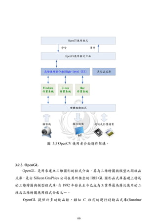
![3.2.1. ARtoolKit
ARToolKit 是計算機視覺追蹤函式庫,允許建立擴增實境應用程序將虛擬
影像疊加在真實世界中。要做到這一點,利用視訊追蹤能力,並即時計算標記
相對於攝像機之位置和方向。找到相關位置後,利用 OpenGL(Open Graphic
Library)繪製三維虛擬物件並準確地疊加在標記之上。所以針對擴增實境之標記
應用,ARToolKit 解決了「標記追蹤」與「虛擬物件互動」這兩個關鍵技術。
ARToolKit的最初是由奈良科學技術研究所(Nara Institute of Science and
Technology)的Kato等人[7]於 1999 年所開發,並且被公佈在華盛頓大學的HIT
實驗室(University of Washington HIT Lab) 目前可以從SourceForge[73]取得這個
。
套件開放原始碼,至於更完善之商業版本則可從ARToolWorks[77]中取得相關資
訊。
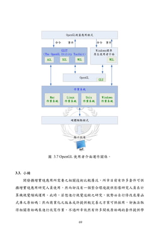
ARToolKit是一套跨平台的函式庫 在不同平台之硬體處理部分可能略有不
,
同,而本文將在Windows環境上實作,故只針對ARToolKit在Windows上之架構
做一討論,如圖 3.3為ARToolKit運作架構圖,其透過DSVL(Direct Show Video
Library)函式庫來取得攝影機之影像,及透過載入VMRL格式之三維物件模型,
最後利用OpenGL進行三維繪製作業,當然ARToolKit的核心程式部分包含了標
記之視訊追蹤與物件之定位,至於詳細運作則不在此介紹。
61](https://image.slidesharecdn.com/markerlessaugmentedrealityplatformdesignandverificationoftrackingtechnologies-110726224337-phpapp01/85/slide-73-320.jpg)
![外部變數,將導致程式間之耦合性變強,若要改寫成動態模組化之設計,將會
碰到如何解決程式間之耦合性問題,所以靜態連結之擴增實境應用程式是較為
容易發展的一種實現方式。
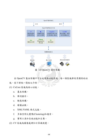
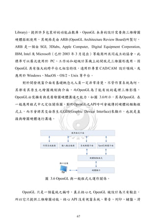
3.2.2. OpenCV
OpenCV的全稱是Open Source Computer Vision Library,是一個跨平台的計
算機視覺函式庫。OpenCV是由英特爾(Intel®)公司發起並參與開發,以BSD認
證方式授權發行,可以在商業和研究領域中免費使用;另外如果系統有英特爾
的IPP(Intel® Integrated Performance Primitives)函式庫,系統將自動載入並搭配
硬體資源達到最佳化之運作模式。OpenCV可用於開發即時的圖像處理、計算
機視覺以及模式識別程式。依據Learning OpenCV[52]一書中對各個模組的介
紹,本文重新修改繪製OpenCV的應用程式運作架構圖如圖 3.4所示。
63](https://image.slidesharecdn.com/markerlessaugmentedrealityplatformdesignandverificationoftrackingtechnologies-110726224337-phpapp01/85/slide-75-320.jpg)


![參考文獻
[1] Sutherland, I. E., “The Ultimate Display,” Proceedings of IFIP Congress, pp.
506-508, 1965.
[2] Sutherland, I. E., “A Head-Mounted Three Dimensional Display,” Proceedings of
the AFIPS Fall Joint Computer Conference, pp. 757-764, 1968.
[3] Dixon, S., “A History of Virtual Reality in Performance,” International Journal
of Performance Arts and Digital Media, Vol. 2 No. 1, pp. 23-54, 2006.
[4] Haller, M., Billinghurst, M., and Thomas, B., “Emerging Technologies of
Augmented Reality Interfaces and Design,” Idea Group Publishing, USA,
Chap.13, pp. 262, 2006.
[5] Milgram, P., Takemura, H., Utsumi, A. and Kishino, F., “Augmented Reality: A
Class of Displays on the Reality-Virtuality Continuum,” Telemanipulator and
Telepresence Technologies, SPIE Proceedings Vol. 2351, pp. 282-292,
November, 1994.
[6] Azuma, R., “A Survey of Augmented Reality,” Presence: Teleoperators and
Virtual Environments, Vol. 6, No. 4, pp. 355-385, August 1997.
[7] Kato, H. and Billinghurst, M., “Marker Tracking and HMD Calibration for a
Video-Based Augmented Reality Conferencing System,” in IWAR ’99:
Proceedings of the 2nd, IEEE and ACM International Workshop on Augmented
Reality, pp. 85-94, IEEE Computer Society, 1999.
[8] Kan, T. W., Teng C.H. and Chou, W. S., “Applying QR Code in Augmented
Reality Applications,” International Conference on Virtual Reality Continuum
and Its Applications in Industry, Yokohama, Japan, pp. 253-257, December,
2009.
[9] Gordon, I. and Lowe, D. G., “Scene Modeling, Recognition and Tracking with
Invariant Image Features,” International Symposium on Mixed and Augmented
4](https://image.slidesharecdn.com/markerlessaugmentedrealityplatformdesignandverificationoftrackingtechnologies-110726224337-phpapp01/85/slide-86-320.jpg)
![Reality (ISMAR), Arlington, VA, pp. 110-119, 2004.
[10] Gordon, I. and Lowe, D. G., “What and Where: 3D Object Recognition with
Accurate Pose,” Toward Category-Level Object Recognition, Springer-Verlag,
pp. 67-82, 2006.
[11] Yuana, M.L., Ongb, S.K., Nee, A.Y.C., “A Generalized Registration Method for
Augmented Reality Systems,” Computers & Graphics Vol. 29, Issue 6, pp.
980-997, December, 2005.
[12] Vallino, J. R., “Interactive Augmented Reality”, PhD Thesis, Department of
Computer Science, University of Rochester, New York, The USA, 1998.
[13] Billinghurst, M., Kato, H. and Poupyrev, I., “The MagicBook: A Transitional
AR Interface,” Computers & Graphics, Vol. 25, Issue 5, pp. 745-753, 2001.
[14] Bötschi, K., Voegtli, B., Juchli, P., Fjeld, M., Fredriksson, J., Ejdestig, M. and
Duca, F., “Tangible User Interface for Chemistry Education: Comparative
Evaluation and Re-Design,” in CHI ’07: Proceedings of the SIGCHI conference
on Human factors in computing systems, pp. 805-808, May, 2007.
[15] Shelton, B. E. and Hedley, N. R., “Using Augmented Reality for Teaching
Earth-Sun Relationships to Undergraduate Geography Students,” First IEEE
International Augmented Reality Toolkit Workshop, Darmstadt, Germany,
September, 2002.
[16] Shelton, B. E., “How Augmented Reality Helps Students Learn Dynamic
Spatial Relationships,” Ph.D. Dissertation, College of Education, University of
Washington, 2003.
[17] Samset, E., Schmalstieg, D., Sloten, J. V., Freudenthal, A., Declerck, J.,
Casciaro, S., Rideng, Ø., Gersak, B., “Augmented Reality in Surgical
Procedures,” Proceedings of SPIE Medical Imaging, Vol. 6806, Issue 1, pp.
68060K-68060K-12, February, 2008.
[18] Fischer, J., Neff, M., Freudenstein D. and Bartz1, D., “Medical Augmented
Reality Based on Commercial Image Guided Surgery,” Eurographics
5](https://image.slidesharecdn.com/markerlessaugmentedrealityplatformdesignandverificationoftrackingtechnologies-110726224337-phpapp01/85/slide-87-320.jpg)
![Symposium on Virtual Environments, pp. 83-86, 2004.
[19] Henderson, S., and Feiner, S., “Evaluating the Benefits of Augmented Reality
for Task Localization in Maintenance of an Armored Personnel Carrier Turret,”
Proceeding of IEEE International Symposium on Mixed and Augmented
Reality, pp. 135-144, October 2009.
[20] Vlahakis, V., KARigiannis, J., Tsotros, M., GounARis, M., Almeida, L.,
Stricker, D., Gleue, T., Christou, I.T., CARlucci, R., Ioannidis, N.,
“ARcheoguide: First Results of an Augmented Reality, Mobile Computing
System in Cultural Heritage Sites,” ACM International Conference on Virtual
Reality, ARcheology, and Cultural Heritage, pp.131-140, 2001.
[21] Huang, C. R., “The Vision-Base Interaction on Augmented Exhibition
Environments,” Ph.D. Dissertation, Department of Electrical Engineering,
National Cheng Kung University Tainan, Taiwan, R.O.C., June, 2005.
[22] Heikkila, J. and Silven, O., “A Four-Step Camera Calibration Procedure with
Implicit Image Correction,” In Proc. of IEEE Computer Vision and Pattern
Recognition, pp. 1106-1112, 1997.
[23] Hu, W., Tan, T., Wang, L. and Maybank, S., “A Survey on Visual Surveillance
of Object Motion and Behaviors,” IEEE Transactions on Systems, Man and
Cybernetics, Part C: Applications and Reviews, Vol. 34, pp. 334-352, 2004.
[24] Longa, W. and Yang, Y. H., “Stationary Background Generation: An Alternative
to the Difference of Two Images,” Vol. 23, No. 12, pp. 1351-1359, 1990.
[25] Lai, Andrew H. S. and Yung, Nelson H. C., “A Fast and Accurate Scoreboard
Algorithm for Estimating Stationary Background in an Image Sequence,” Proc.
of IEEE Int’l Symp. on Circuits and Systems, Vol. 4, 241-244, 1998.
[26] Lucas, B. D. and Kanade, T., “An Iterative Image Registration Technique with
an Application to Stereo Vision,” Proceedings of Imaging Understanding
Workshop, pp. 121-130, 1981.
[27] Horn, B.K.P. and Schunck, B.G., “Determining Optical Flow,” Artificial
6](https://image.slidesharecdn.com/markerlessaugmentedrealityplatformdesignandverificationoftrackingtechnologies-110726224337-phpapp01/85/slide-88-320.jpg)
![Intelligence, Vol. 17, pp. 185-203, 1981.
[28] Zang, Q. and Klette, R., “Object Classification and Tracking in Video
Surveillance,” Computer Analysis of Images and Patterns, Vol. 2756, pp.
198-205, August, 2003.
[29] Paragios N.and Deriche, R., “Geodesic Active Contours and Level Sets for the
Detection and Tracking of Moving Objects,” IEEE Trans. Pattern Anal.
Machine Intell. , Vol. 22, pp. 266-280, 2000.
[30] Lowe, D. G., “Object Recognition from Local Scale-Invariant Features,”
International Conference of Computer Vision, Vol. 60, pp. 1150-1157, 1999.
[31] Lowe, D. G., “Distinctive Image Features from Scale-Invariant Keypoints,”
International Journal of Computer Vision, pp. 91-110, 2004.
[32] Bay, H., Tuytelaars, T., Van Gool, L., “SURF: Speeded Up Robust Features,” In:
ECCV, Vol. 3951, Issue 2, pp. 404-417, July, 2006.
[33] Bay, H., Ess, A., Tuytelaars, T. and Van Gool, L., “Speeded-Up Robust Features
(SURF),” Computer Vision and Image Understanding 110, pp. 346-359, 2008.
[34] Ke, Y. and Sukthankar, R., “PCA-SIFT: A More Distinctive Representation for
Local Image Descriptors,” Computer Vision and Pattern Recognition, Vol. 2, pp.
506-513, 2004.
[35] Morel, J.M. and Yu, G., “ASIFT: A New Framework for Fully Affine Invariant
Image Comparison,” SIAM Journal on Imaging Sciences, Vol. 2, Issue 2, pp.
438-469, 2009.
[36] Tanizaki, H., “Non-Gaussian State-Space Modeling of Nonstationary Time
Series,” J. Amer. Statist. Assoc.82, pp. 1032-1063, 1987.
[37] Guan, T. and Duan, L., “Recovering Pose and Occlusion Consistencies in
Augmented Reality Systems Using Affine Properties,” Sensor Review, Vol. 30
Issue 2, pp. 148-158, 2010.
[38] Zheng, Z., “Gesture Interface for 3D Scene Based on CAMSHIFT Fingertip
Tracking,” Department of Computer Science, University of Stony Brook, New
7](https://image.slidesharecdn.com/markerlessaugmentedrealityplatformdesignandverificationoftrackingtechnologies-110726224337-phpapp01/85/slide-89-320.jpg)
![York.
[39] McKenna, S., Jabri, S., Duric, Z., Rosenfeld A. and Wechsler, H., “Tracking
Groups of People,” Computer Vision and Image Understanding, Vol. 80, pp.
42-56, 2000.
[40] Masoud O. and Papanikolopoulos, N. P., “A Novel Method for Tracking and
Counting Pedestrians in Real-Time Using a Single Camera,” IEEE Trans.
Vehicular Tech., Vol. 50, No. 5, pp. 1267-1278, 2001.
[41] Nilsen, T., Looser, J., “Tankwar: Tabletop War Gaming in Augmented Reality,”
In Proceedings of the 2nd International Workshop on Pervasive Gaming
Applications (PerGames), 2005.
[42] Saenz, A., “Augmented Reality to Help Military Mechanics Fix Vehicles
(Video),” Singularity Hub, January, 2010.
[43] Molla, E. and Lepetit, V., “Augmented Reality for Board Games,” In
Proceedings of the International Symposium on Mixed and Augmented Reality,
pp. 253-254, 2010.
[44] Kakuta, T., Oishi, T. and Ikeuchi, K., “Virtual Asukakyo: A Restoration of an
Archeological Site with Mixed Reality Technology and Expansion into a Tour
Guide System,” Computer Vision Laboratory, University of Tokyo, pp. 172-175,
Jun, 2007.
[45] Bonanni, L., Lee, C. H. and Selker, T., “Attention-Based Design of Augmented
Reality Interfaces,” CHI '05 Extended Abstracts on Human Factors in
Computing Systems, April 02-07, 2005, Portland, OR, USA, pp. 1228-1231,
2005.
[46] Lee, C. H. J., Bonanni, L., Espinosa, J. H., Lieberman, H. and Selker, T.,
“Augmenting Kitchen Appliances with a Shared Context using Knowledge
about Daily Events,” Proceedings of the 11th International Conference on
Intelligent User Interfaces, pp. 348-350, 2006.
[47] 呂其展,“運用影像序列建構與顯示三維地形模型之研究",國立成功大
8](https://image.slidesharecdn.com/markerlessaugmentedrealityplatformdesignandverificationoftrackingtechnologies-110726224337-phpapp01/85/slide-90-320.jpg)
![學資訊工程學系碩士論文,台南,第 9-16 頁,2002。
[48] 王燕超,“從擴增實境觀點論數位學習之創新",國立臺灣師範大學圖文
傳播學系,台北,2006。
[49] 李洢杰,“應用光流原理進行近景視訊影像同名點雲自動化追蹤與量
測", 國立成功大學測量工程學系碩士論文,台南,第 4-5 頁,2003。
[50] 賴丙全,“利用多攝影機進行移動物三維定位及追蹤", 國立中央大學
土木工程研究所碩士論文,台南,第 3-6 頁,2007。
[51] Bimber, O. and Raskar, R., “Spatial Augmented Reality: Merging Real and
Virtual Worlds,” A. K. Peters, Ltd., Wellesley, MA, USA, Chap.1, pp. 1-7, July,
2005.
[52] Bradski, G., Kaehler, A., “Learning OpenCV,” O'Reilly Media, September
2008.
[53] Shreiner, D. and The Khronos OpenGL ARB Working Group, “OpenGL
Programming Guide,” Addison-Wesley Professional, USA, 2009.
[54] Francis S Hill Jr., Stephen M Kelley (Author) “Computer Graphics Using
OpenGL (3rd Edition),” Prentice Hall, USA, Chap.7, 2006.
[55] 徐明亮,盧紅星,王琬,“OpenGL 遊戲編程",機械工業出版社,中國,
第 7-22 頁,2008。
[56] 項志鋼,“Computer Graphics with OpenGL",清華大學出版社,中國,
第 70-79 頁,2007。
[57] Denso-Ware, http://www.denso-wave.com/
[58] QR Code.com, http://www.denso-wave.com/qrcode/index-e.html
[59] QR-Code Generator, http://qrcode.kaywa.com/
[60] Lumus, http://www.lumus-optical.com/
[61] Star Wars, http://www.starwars.com/
[62] Transpost, http://www.hitachi.co.jp/New/cnews/month/2007/08/0806.html
9](https://image.slidesharecdn.com/markerlessaugmentedrealityplatformdesignandverificationoftrackingtechnologies-110726224337-phpapp01/85/slide-91-320.jpg)
![[63] N-3D, http://www.aircord.co.jp/blog/2010/07/n-3d-demo.php
[64] Heliodisplay, http://www.io2technology.com/
[65] Contact lenses, http://spectrum.ieee.org/biomedical/bionics/
augmented-reality-in-a-contact-lens/0
[66] Nintendo, http://www.nintendo.tw/wiisportsresort/
[67] Sony EyePet, http://www.eyepet.com
[68] Rob Hess, http://blogs.oregonstate.edu/hess/
[69] SiftGPU, http://www.cs.unc.edu/~ccwu/siftgpu/
[70] SURF, http://www.vision.ee.ethz.ch/~surf/
[71] GPU SURF, http://homes.esat.kuleuven.be/~ncorneli/gpusurf/
[72] ARToolKit, http://www.hitl.washington.edu/artoolkit/
[73] ARToolKit SourceForge page, http://sourceforge.net/projects/artoolkit
[74] NyARToolKit, http://nyatla.jp/nyartoolkit/
[75] jARToolKit, http://sourceforge.net/projects/jartoolkit/
[76] FLARToolkit, http://www.libspark.org/wiki/saqoosha/FLARToolKit/en
[77] ARToolKit Professional, http://www.artoolworks.com/
[78] ARTag, http://www.artag.net/
[79] ARToolKit Plus, http://studierstube.icg.tu-graz.ac.at/handheld_ar/
artoolkitplus.php
[80] Goblin XNA, http://graphics.cs.columbia.edu/projects/goblin/
[81] DART, http://www.cc.gatech.edu/projects/dart/
[82] Metaio, http://www.metaio.com/
[83] Metaio Unifeye SDK, http://www.metaio.com/ /products/sdk/
[84] PITOECH CO.,LTD., http://www.pitotech.com.tw
[85] Vizard, http://www.worldviz.com
[86] D'Fusion, http://www.t-immersion.com/
[87] Axis 3D Technology, Inc., http://www.axis3d.com.tw/
[88] DirectShow System Overview, http://msdn.microsoft.com/
10](https://image.slidesharecdn.com/markerlessaugmentedrealityplatformdesignandverificationoftrackingtechnologies-110726224337-phpapp01/85/slide-92-320.jpg)
![[89] Wikipedia, http://zh.wikipedia.org/zh-tw/
[90] Engineering Navi, http://kougaku-navi.net/
11](https://image.slidesharecdn.com/markerlessaugmentedrealityplatformdesignandverificationoftrackingtechnologies-110726224337-phpapp01/85/slide-93-320.jpg)
![論文發表
[1] 鍾德煥、李正豪、王順吉,“擴增實境實做技術探討與分析",第十九屆
國防科技學術研討會論文集,桃園龍潭,第 911-918 頁,2010。
[2] 王順吉、鍾德煥、李正豪、翁志嘉,“無標記擴增實境實驗平台建置與視
覺追蹤技術分析",2011 電子商務與數位生活研討會論文集,台北,第
1059-1075 頁,2011。
12](https://image.slidesharecdn.com/markerlessaugmentedrealityplatformdesignandverificationoftrackingtechnologies-110726224337-phpapp01/85/slide-94-320.jpg)