Download to read offline
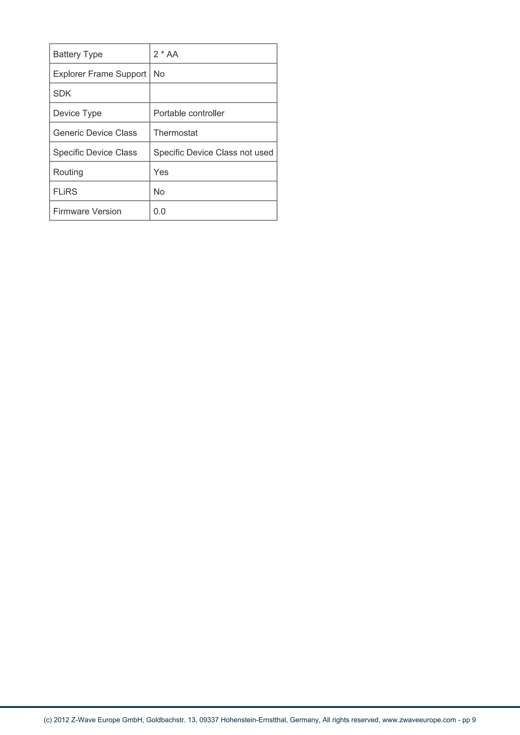

This document provides instructions and specifications for a set combining a programmable 7-day room thermostat and a wirelessly controlled relay switch for central heating control. The thermostat can be programmed with up to six temperature settings per day. The relay switch is used to control heating loads up to 3A/230V and can be operated locally or controlled by the thermostat wirelessly. Instructions are provided for installation, inclusion in a Z-Wave network, configuration, and operation of both devices.


![Coded Agents – with UiPath SDK + LangGraph [Virtual Hands-on Workshop]](https://cdn.slidesharecdn.com/ss_thumbnails/codedagentsdeck-251215155422-5497c599-thumbnail.jpg?width=640&height=640&fit=bounds)


