Download as PDF, PPTX
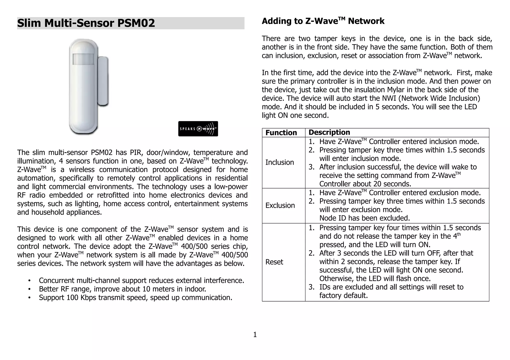
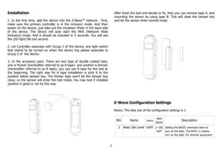

The slim multi-sensor PSM02 has 4 sensors (PIR, door/window, temperature, and illumination) and uses Z-Wave wireless technology. It can be included in a Z-Wave home automation network to remotely control devices. When motion, door, temperature, or light changes are detected, it will report to the network. It has different operating modes (test, home automation, security) and can be configured via the Z-Wave controller.