This document provides specifications and simulation results for a photovoltaic (PV) nickel-metal hydride (Ni-MH) battery system. It includes specifications for Ni-MH battery packs and solar photovoltaic panels. Simulation circuits and results are shown for charging the batteries from the solar panels under different conditions. Additional simulations model the full PV-battery system over a 24-hour period to analyze charging based on changing solar intensity over time. The document contains detailed specifications, modeling parameters, and simulation results to evaluate performance of the PV-NiMH battery system.
![1.1 Ni-MH Battery Specification
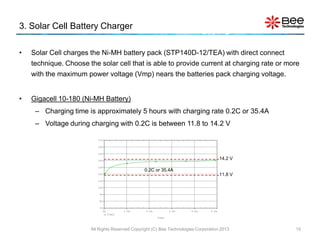
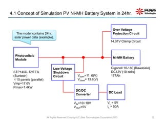
KAWAZAKI’s Ni-MH Batteries : Gigacell (10-180)
• Rated Voltage ..................12 [V]
• Capacity............................177 [Ah] (Approximately)
• Energy Capacity................2.1 [kWh]
• Max Output........................48 [kW] 10 Ni-MH cells are
in series.
• Rated Charge................ 0.2C5 [A] ( SoC=100% )
All Rights Reserved Copyright (C) Bee Technologies Corporation 2013 3](https://image.slidesharecdn.com/manualoutputdc-130306225449-phpapp01/85/PV-Ni-MH-Battery-System-Output-is-DC-3-320.jpg)
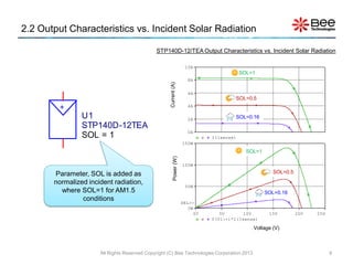
![2.1 Solar Cells Specification
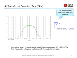
Suntech’s photovoltaic module : STP140D-12/TEA
• Maximum power (Pmax)............140[W]
• Voltage at Pmax (Vmp).............17.6[V]
• Current at Pmax (Imp)...............7.95[A]
• Short-circuit current (Isc)...........8.33[A]
• Open-circuit voltage(Voc)..........22.4[V]
1482mm
All Rights Reserved Copyright (C) Bee Technologies Corporation 2013 8](https://image.slidesharecdn.com/manualoutputdc-130306225449-phpapp01/85/PV-Ni-MH-Battery-System-Output-is-DC-8-320.jpg)