The document summarizes information about a main circuit breaker, including:
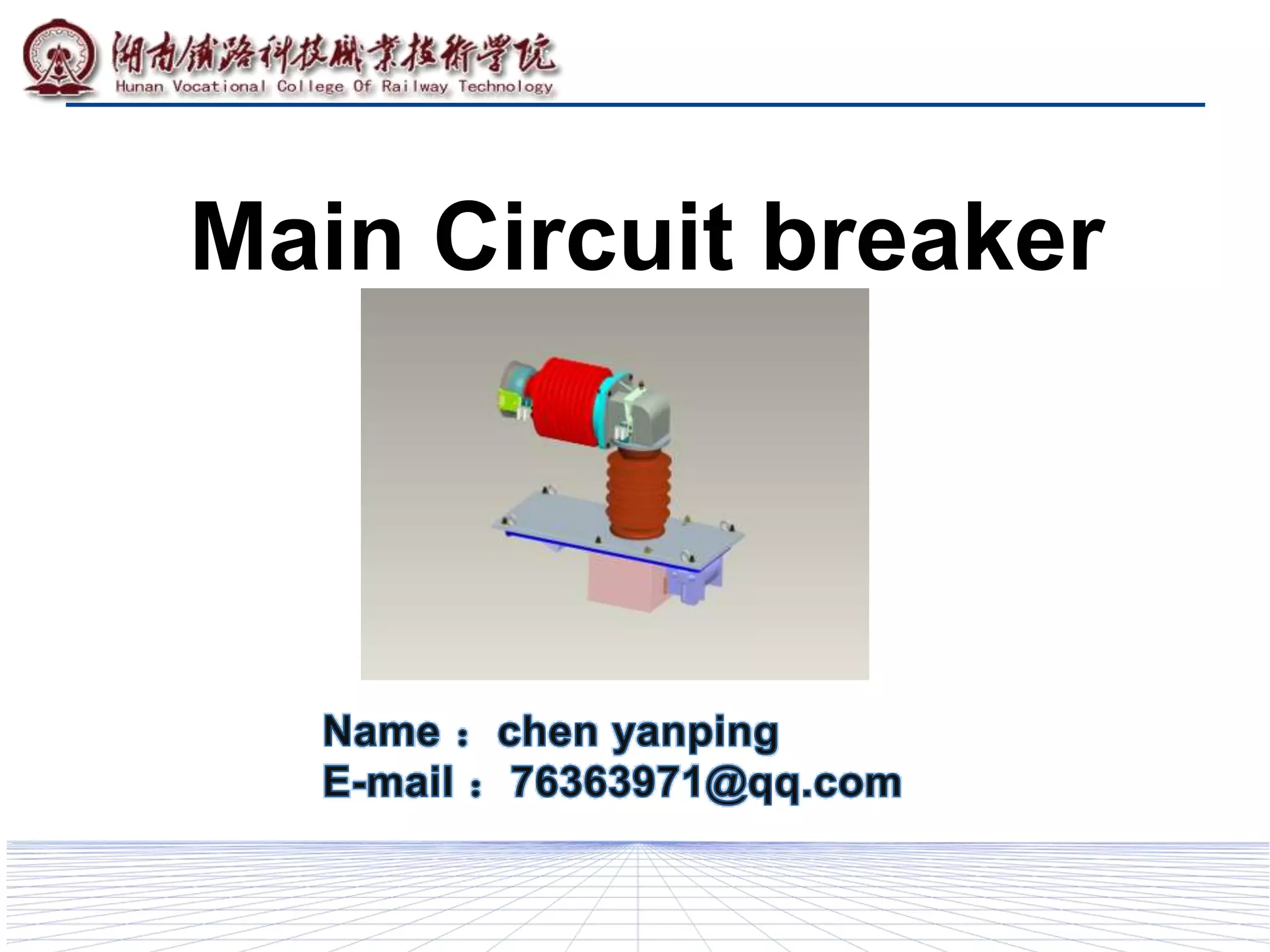
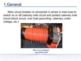
- It is connected in series to switch on or off the catenary side circuit and protect it from short circuits, overloads, undervoltage, etc.
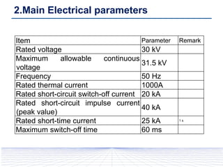
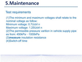
- It has key electrical parameters like a rated voltage of 30kV, maximum continuous voltage of 31.5kV, and rated short-circuit switch-off current of 20kA.
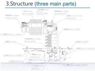
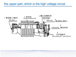
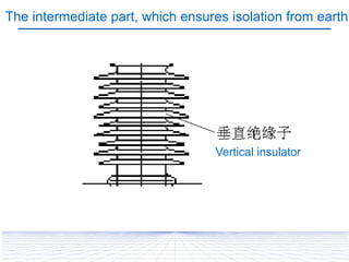
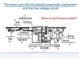
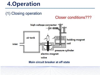
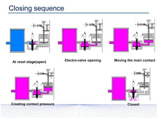
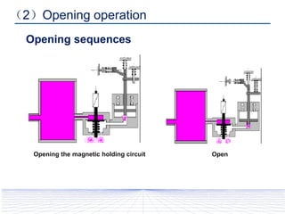
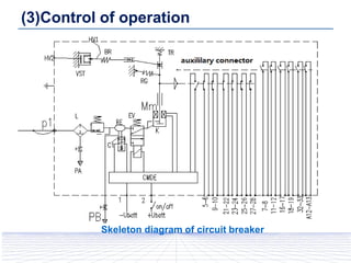
- It has three main parts: the upper high voltage circuit, intermediate isolation from earth, and lower electro-pneumatic mechanism and low voltage circuit.
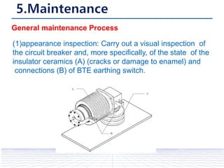
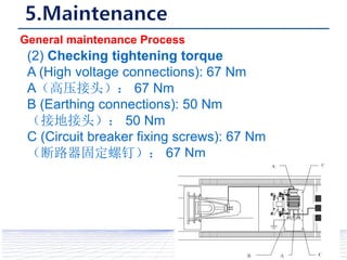
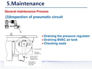
- Maintenance involves appearance inspection, checking tightening torques, and inspecting the pneumatic circuit.