More Related Content
Similar to Magazin 32 35_awinning_formula_e (20)
Magazin 32 35_awinning_formula_e
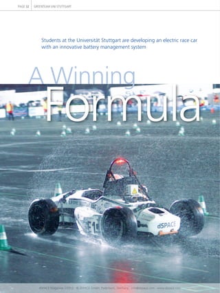
- 1. Students at the Universität Stuttgart are developing an electric race car
with an innovative battery management system
Formula
A Winning
PAGE 32 GREENTEAM UNI STUTTGART
dSPACE Magazine 1/2012 · © dSPACE GmbH, Paderborn, Germany · info@dspace.com · www.dspace.com
- 2. Formula Student has very strict rules on the safety of electrically powered
race cars. GreenTeam Uni Stuttgart guarantees safety by using dSPACE
technology to develop their high-speed vehicle.
The new dSPACE MicroAutoBox II controls the vehicle dynamics, monitors
the safety system and controls the battery management.
The GreenTeam in Formula
Student Electric
GreenTeam Uni Stuttgart is a non-
profit organization with over 30
active student members who develop
and build electric race cars accord-
ing to the rules of Formula Student
Electric. What’s special is that the
entire development process, from
the idea and design for the car to
parts manufacture to prototype
assembly and testing, is carried out
by the students themselves.
Founded in 2009, the team’s goals
are to develop a Formula Student
race car with a purely electric drive
and to actively participate in Formula
Student Electric competitions.
To develop their first electric race
car, the students optimized and
modified the racing team’s combus-
tion engine-driven 2008 world
championship vehicle, the F0711-3.
Their main focus was on integrating
the electric motor, the high-voltage
battery and the necessary control
system.
Electrical Vehicle Components
The E0711-2 race car that was
developed for the 2010/11 season
has two 50-kW electric motors, type
AMK DT7-80-20-POW, installed lon-
gitudinally, which drive the rear
wheels independently of each other.
The required operating voltage is
supplied by a high-voltage Lithium
polymer (LiPo) battery. It has 8.4
kWh capacity with a maximum volt-
age of 588 V and an energy density
of 180 Wh/kg. The batteries in the
Stuttgart race car are arranged in
three series of 140 sequentially
switched cells, giving the vehicle
three independent batteries con-
nected in parallel.
Functions of a Battery Manage-
ment System
A battery management system
(BMS) controls the electrical and
thermal processes in a battery of
several connected, rechargeable
cells that have to be monitored and
controlled. In automotive technol-
ogy, a BMS also controls different
vehicle operating states, optimizes
the battery’s lifetime and perfor-
mance, and if necessary puts it into
a safe state.
For example, if the vehicle is switched
off, the BMS goes into sleep mode.
If the vehicle is in waking mode
(programmable cyclically), the BMS
can monitor variables such as voltage,
current strength and temperature
The E0711-2
Motors: 2 permanent magnet synchronous motors,
each 50 kW
Control: MicroAutoBox II
Recharcheable batteries: Lithium polymer pouch cells with 588 V
Weight: 266 kg
Acceleration: 0 to 100 km/h in 3.0 s
PAGE 33
dSPACE Magazine 1/2012 · © dSPACE GmbH, Paderborn, Germany · info@dspace.com · www.dspace.com
- 3. the battery in an electric race car
has to keep going till it reaches the
finish line without recharging, even
in a long-distance (22 km) race.
Conception of the BMS
This is the approach the team uses
to ensure the battery operates reli-
GREENTEAM UNI STUTTGARTPAGE 34
Battery management system: The dSPACE MicroAutoBox II is connected to the dSPACE inter-
face module PGI1 via the LVDS bus and controls the BMS. Via SPI buses, the PGI1 receives
information from the cell supervisory controllers that monitor the individual cells.
“With the MicroAutoBox II and the dSPACE Programmable Generic Inter-
face, we can capture and control the high-voltage battery’s elementary
variables precisely.” Leonardo Uriona, E0711-2 Team Leader
ably: The consumed power is con-
trolled as a function of temperature
T and state of charge SOC. Over-
charging and deep discharge are
prevented by interval control: The
charging process is interrupted at
the top limit (4.2 V), and then all
the cells are balanced to the lowest
for irregularities or failures. These
are transmitted to the driver and the
racing team in real time so that they
can take appropriate action.
Requirements for the Battery
Management System
The rules of Formula Student Elec-
tric Germany (FSE) state that the
battery system in the E0711-2 race
car must switch off automatically if
its cells are working outside the
specified parameter limits. To cover
the BMS’ entire functional scope,
other input variables must also be
captured and evaluated in order to
optimize battery management.
These include the voltages and tem-
peratures of the individual cells.
States such as overcharging, deep
discharge, overcurrents, short cir-
cuits and the ambient temperature
also have to be captured. This mini-
mizes the risk of a weak or failing
battery cell affecting the other cells
in the series-connected system,
which would impair overall perfor-
mance. This is especially important
in Formula Student Electric, because
MicroAutoBox II
PGI1
LVDS
SPI
SPI
CSC CSC CSC CSC
CSC CSC CSC CSC
Cells
Cells
dSPACE Magazine 1/2012 · © dSPACE GmbH, Paderborn, Germany · info@dspace.com · www.dspace.com
- 4. Leonardo Uriona (right)
Leonardo Uriona is team leader for
the overall vehicle electronics in the
GreenTeam Uni Stuttgart, Germany.
Edward Eichstetter (left)
Edward Eichstetter is team leader for
the overall vehicle in the GreenTeam
Uni Stuttgart, Germany.
PAGE 35
The bottom battery module (BOT) contains battery cells 1-24, the middle modules (MID)
contain battery cells 25-121, and the TOP module contains battery cells 122-140.
The bottom module forms the interface to the dSPACE PGI1 module via the SPI bus.
The top module ends the daisy chain of the bus system that transports the data.
Bottom
Cells 1-24
Daisy Chain
from PGI via SPI
Middle
Cells 25-121
Top
Cells 121-140
Daisy Chain
„up“ and „down“
voltage. As soon as all the cells have
the same voltage, another attempt
is made to charge them up to 4.2 V.
The charging process continues in
this iterative fashion until all the
cells have reached their maximum
SOC. At the bottom charge limit
(3.5 V), the system calculates the
expected voltage drop so that the
battery load does not go below the
minimum.
The BMS can use the SOC curves,
the temperature and the kilometers
still to be driven in order to calculate
how much power can be released.
It does this with the dSPACE Micro-
AutoBox II.
dSPACE Technology in the Race Car
The MicroAutoBox II is the computing
center for the battery management
system. It monitors the overall sys-
tem and processes the information
from the dSPACE Programmable
Generic Interface (PGI1) via a low-
voltage differential signaling (LVDS)
bus. The PGI1 then communicates
with the individual cell supervisory
controllers (CSCs) via the Serial
Peripheral Interface (SPI).
The battery cells and various control
mechanisms are evaluated by a BMS
model based on a dSPACE engineer-
ing solution. The dSPACE-supported
battery management system has
proved a success for GreenTeam and
will be used in the same form in actual
competition. The high reliability of
the vehicle functions is demonstrated
by the racing team’s many wins with
their second-generation electric race
car.
Development Progress
The GreenTeam Uni Stuttgart has
already taken 3 top places in 4 com-
petitions. In 2010, they won the
overall victory in Germany and in
Italy. The team showed its determi-
nation again in 2011, winning sec-
ond place in Italy.
These successes inspired the team
to compete on the Hockenheimring
in Germany and in Italy every year
with the E0711-2, a newly devel-
oped and improved race car. The
team also aims to take part in other
international competitions.
In the meantime, GreenTeam is busy
working on the E0711-3, the third
generation of their self-developed
electric race cars.
Edward Eichstetter
Leonardo Uriona
GreenTeam Uni Stuttgart
dSPACE Magazine 1/2012 · © dSPACE GmbH, Paderborn, Germany · info@dspace.com · www.dspace.com