Lyapichev. Problems in numerical analysis of CFRDs (ICOLD Bull.155)6 p.)
•
0 likes•108 views

The document discusses several challenges and developments in numerically analyzing concrete faced rockfill dams (CFRDs). It notes that until recently, CFRDs were designed based on experience rather than analysis. Accurate models have since shown issues like excessive compressibility of downstream rockfill adversely impacting the concrete face. The document also discusses modeling earthquakes, the need for structure-specific models in some cases, and ensuring nonlinear analysis convergence. Overall, it emphasizes the importance of numerical analysis as a tool to supplement—not replace—engineering judgment, especially for extrapolating lessons from incidents at high CFRDs.

Recommended
Recommended
More Related Content
What's hot
What's hot (18)
Similar to Lyapichev. Problems in numerical analysis of CFRDs (ICOLD Bull.155)6 p.)
Similar to Lyapichev. Problems in numerical analysis of CFRDs (ICOLD Bull.155)6 p.) (20)
More from Yury Lyapichev
More from Yury Lyapichev (20)
Recently uploaded
Recently uploaded (20)
Lyapichev. Problems in numerical analysis of CFRDs (ICOLD Bull.155)6 p.)
- 1. Extracts from ICOLD Bulletin 155 on seismic (dynamic) analysis of CFRD: by Lyapichev Yury (member of ICOLD Committee on dam analysis & design) 1. Some serious problems in numerical analysis of CFRDs. Until a very recent period, it was considered useless to perform numerical analyses of CFRDs and promoters of this type of dam used to claim that their safe design was the result of experience and pure empirism. Until recently the trend in CFRD design, based on the intuition of specialists, was to pay great care on the placing of rockfill materials just below the concrete slabs with which these dams are provided, and to accept much less care in the downstream area (thicker layers, lower quality of rock, etc). Some of these dams have shown many damages on slabs and high leakage, due to excessive and uneven deformability of rockfill zones. Accurate models with non-linear properties of rockfill have shown the adverse effect of excessive compressibility of the downstream shell on the deformations imposed to the concrete face. The influence of excessive downstream slopes has also been put into evidence. It is still difficult to obtain realistic rockfill properties from laboratory tests, due to the size of elements and samples. Research is underway to understand the plastification phenomenon at the scale of the block, whose objective is to provide an extrapolation law to derive the behavior of large size rockfill from more manageable samples with only small blocks. One of the difficulties brought by non-linear process in FE analyses is the need to check the process convergence. Non-linear software generally use only a global convergence criterion, based on the proportion of unbalanced energy relative to the total deformation energy. This criterion as proved to fail in some specific cases, e.g. opening of joints in a concrete slab of a CFRD. The reason is that even a small unbalanced local force may prevent a whole structure from collapsing (this is the “zipper” effect). Only the engineer can detect such critical cases, and it is therefore necessary that all software with non- linear capabilities propose means to detect (and visualize) the amount of local unbalanced forces, at different steps of the analysis. A number of incidents affected several recent high CFRDs all over the world, which has finally enlighted the interest of numerical models to keep control on extrapolation towards higher dams. It has been shown that not only stresses increase proportionally to the dam height, but also that a scale effect appears, which may affect displacements and even the dam overall stability. The valley shape has also been identified an important factor, which induces bank-to-bank movements of the rockfill mass and, as a consequence, very high compressive stresses in the concrete face. Such problems are indeed quite complex for numerical analyses, because: • The problem is in general tri-dimensional, • The response of rockfill to loads requires adequate non-linear constitutive laws with a rather large displacements including sliding movements along the rock abutments, • The huge contrast between the large, deformable rockfill and the slender, rigid concrete face, creates numerical problems, all the more as sliding may occur along the contact surface between both materials. In this context, Problem 10B ‘Analysis of CFRD dam including concrete face loading and deformation’ was proposed for the 10th benchmark workshop, based on published information of the 145 m high Mohale dam in Lesotho. The main reason for these damages was identified as a high compressibility of rockfill under high stresses, due to the breakage of rock particles. It should be emphasized that the three recent incidents, including the Mohale dam, show the need to carefully evaluate and analyze every aspect of a project when extrapolating from precedent. This should be based on good engineering judgment and complemented with detailed analysis tools. 2. Modeling for earthquakes actions Similarly to the hydraulic loads, earthquake loads may vary in intensity, frequency and duration, depending on the site and the return period under consideration. The revised bulletin 72 provides three definitions for earthquakes:
- 2. • The Safety Evaluation Earthquake (SEE), • The Operation Basic Earthquake (OBE), • The Reservoir Triggered Earthquake (RTE). The complexity of the model and the analysis should gradually increase according to the severity of the seismic load under examination and to the hazard level of the dam to be constructed. For instance, when the effects of a strong earthquake (SES, maximum credible earthquake or very high return period earthquake, typically in the range of 5000-10000 years) for a high-hazard dam has to be evaluated, its retaining capacity must be assured, implying the dam might suffer significant damages without collapsing so that an accurate non-linear analysis may be needed to assess its stability. On the opposite, the effect of the Operating (or Design) Basis Earthquake (OBE or DBE) for a low-hazard dam can be evaluated with a simpler linear- elastic analysis, by assigning suitable safety margins. Based on the above discussion, it may be concluded that the behavior of dams during strong earthquake ground shaking, whether embankment or concrete dams, is highly non-linear. It is true that computer science, numerical analysis methods, and applied mechanics have experienced tremendous developments since the 1960s. Quite a few numerical models have been developed in the domains of constitutive elasto- plastic models, fracture mechanics or damage mechanics. These developments are very promising, but still contain major shortcomings. They should be considered as a possibility to strengthen engineering judgment rather than the ability to enhance predictive capabilities. Numerical models, when utilized, should be comprehensive enough to represent all-important aspects under the prevailing loading conditions. However, it is still recommended that a comparison between the inelastic response and one obtained using the stable and well-tried linear elastic models be conducted. For example, since limited information is available regarding the behavior of fill dams under earthquakes, only models can be taken as reference for prediction. However, it is acceptable to refer to relatively simplified models (Seed’s linear equivalent, stability analyses and Newmark double integration) to obtain orders of magnitude of irrecoverable displacements, from which an idea of damage can be derived. 3. The need for the development of ad hoc numerical models As mentioned in the preceding paragraph, in some cases it can be proved (especially in the framework of coordinated research activities like the Benchmark Workshops) that none of the existing models can attack a given problem in a satisfactory way. In such instances the need to develop new, ad hoc models becomes apparent, and the problem is taken back one step, to the questions of defining specifications for the new model, identifying the mathematical tools needed, pinpointing the kind and amount of experimental investigations required in order to test, validate, and justify the new model once its mathematical/numerical implementation has been achieved. Sometimes even the basic constitutive laws governing the behaviour of dam materials have to be revisited, and in this context either new kind of laboratory tests have to be devised (and their specifications defined as precisely as possible), ensuring the collaboration of material-science specialists, or the best identification procedures to extract the unknown data from observational data-bases have to be derived, if no feasible laboratory tests can be imagined. All of the above is usually relevant for non linear models, and in this context it has to be emphasised that as the models become more complicated and the material parameters to be used as input become further removed from the realm of simple laboratory tests, the interpretation of model results can sometimes become an indirect, delicate task, which requires a lot of research work and peer contribution/discussion before the newly developed analytical tools can be accepted in the mainstream of dam engineering practice. Once again, the forums of discussion provided by the Benchmark Workshops can prove to be of invaluable assistance in this ongoing process, but utmost care in their organization has to be spent in order that the great amounts of efforts and money required can bear the most effective fruits. The followings topics have been identified:
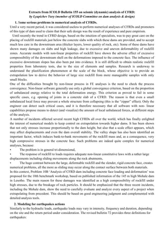
- 3. Topic 3: Movements of rockfill in CFRD during their first impounding. The recent trend in CFRD design, based on the intuition of specialists, was till recently to pay great care on the placing of rockfill materials just below the concrete slabs with which these dams are provided, and to accept much less care in the downstream area (thicker layers, lower quality of rock, etc). Some of these dams have shown many damages on slabs and high leakage, due to excessive and uneven compaction of rockfill zones. Accurate models with non-linear properties of rockfill have shown the adverse effect of excessive compressibility of the downstream shell on the deformations imposed to the concrete face. The influence of excessive downstream slopes has also been put into evidence. It is still difficult to obtain realistic rockfill properties from laboratory testing, due to the size of elements and samples. Research is underway to understand the plastification phenomenon at the scale of the block, whose objective is to provide an extrapolation law to derive the behaviour of large size rockfill from more manageable samples with only small blocks. 4. Rockfill dams with an upstream concrete face (CFRD) Until a very recent period, it was considered useless, if not harmful, to perform numerical analyses of concrete faced rockfill dams, and promoters of this type of dam used to claim that their safe design was the result of experience and pure empirism. Problem 6B proposed in 2001 was indeed attracted only 2 solutions, from France and Japan. Both contributions carried out the analysis in 2 dimensions only (the dam prototype was the 125 m high Ita CFRD in Brazil, a dam in a quite wide valley), and both made use of several constitutive laws for rockfill, which reproduced rather well the displacements during the first impounding. The concrete face was represented in both models, which detected the presence of high stresses. Fig. 11 gives an example of model mesh for a CFR dam, where the rockfill mass as well as the concrete face are presented with volumetric finite elements. When the foundation is made of rock it can be omitted from the model due to its very low compressibility, compared to the rest of the model. Fig. 11 Finite element model for a rockfill dam 1 - Left dam end; 2 - Crest; 3 - Right crest end; 4 - Upstream concrete dam face; 5 - Rock foundation shape A number of incidents affected several recent high CFRDs all over the world, which has finally enlighted the interest of numerical models to keep control on extrapolation towards higher dams. It has been shown that not only stresses increase proportionally to the dam height, but also that a scale effect appears, which may affect displacements and even the dam overall stability. The valley shape has also been identified an important factor, which induces bank-to-bank movements of the rockfill mass and, as a consequence, very high compressive stresses in the concrete face. Such problems are indeed quite complex for numerical analyses, because • The problem is in general tri-dimensional, • The response of rockfill to loads requires adequate non-linear constitutive laws with a rather large displacements including sliding movements along the rock abutments,
- 4. • The huge contrast between the large, deformable rockfill and the slender, rigid concrete face, creates numerical problems, all the more as sliding may occur along the contact surface between both materials. In this context, Problem 10B ‘Analysis of a concrete faced rockfill dam including concrete face loading and deformation’ was proposed for the 10th benchmark workshop, based on published information of the 145 m high Mohale dam in Lesotho. Four solutions were presented, with results under the form of displacements and stresses in the fill during construction, stresses and joint openings in the concrete face. Stresses consistent with the damages observed on the prototype were given by at least 2 solutions. The main reason for these damages was identified as a high compressibility of rockfill under high stresses, due to the breakage of rock particles. The conclusion of the formulator of this theme deserves being quoted: “It should be emphasized that the three recent incidents, including the Mohale dam, show the need to carefully evaluate and analyze every aspect of a project when extrapolating from precedent. This should be based on good engineering judgment and complemented with detailed analysis tools. This applies not only to CFRDs but to any engineering structure”. 5. Behavior of concrete face of CFRD during their first impounding Until recently the trend in CFRD design, based on the intuition of specialists, was to pay great care on the placing of rockfill materials just below the concrete slabs with which these dams are provided, and to accept much less care in the downstream area (thicker layers, lower quality of rock, etc). Some of these dams have shown many damages on slabs and high leakage, due to excessive and uneven deformability of rockfill zones. Accurate models with non-linear properties of rockfill have shown the adverse effect of excessive compressibility of the downstream shell on the deformations imposed to the concrete face (Anthiniac & al., 2002). The influence of excessive downstream slopes has also been put into evidence. It is still difficult to obtain realistic rockfill properties from laboratory tests, due to the size of elements and samples. Research is underway to understand the plastification phenomenon at the scale of the block, whose objective is to provide an extrapolation law to derive the behavior of large size rockfill from more manageable samples with only small blocks. 6. Classification of numerical models in relation to the reliability of their results when applied to real-world problems The role of mathematical models in this complex framework is to include not only advanced tools, like Finite Element analyses, but also more modest ones, such as empirical rules. Those are considered as reliable on the strength of a long practice and frequent, successful applications. Each of them allows to form qualitative judgements of a partial aspect of the dam behaviour. The qualitative judgement can be accompanied, in some cases, by quantitative indices expressing the greater or smaller distance from a dangerous situation. The models should be utilized with a clear perception of their nature of simulation tools. They are only able to compute what would happen if the dam should obey to certain physical laws of behaviour and if the actions were of a certain type and intensity. The accuracy of the answer entails verifications internal to the models and related software validation; instead, the relevance of these answers to the physical world entails a judgement which includes considerations external to the model. The results of the models and the resulting indices should allow the dam engineer to document that the dam complies with codes of practice and official regulations. The application of numerical models to real world problems for a long time suffered from the gap between the specialists of mathematical modeling and planners and managers of dams. The first group includes usually also information system specialists, thanks to which they are able to develop the models to their full potential. The professionals belonging to the second group often prefer to revert to traditional methods of calculation and empirical methods based on their proven experience. Thanks to initiated Benchmark-Workshops, dam engineers now should no longer be dependant on specialists in informatics for
- 5. the mathematical modelling of their problems but they should be able to work with them without language barriers or gaps in knowledge. The available computational tools and the existing numerical methods make nowadays possible to approach mathematically the most typical problems of structure mechanics. On the other hand, limitations of the reliability of the mathematical modelling often occurs because of lack of data on material properties and observations of the structual behaviour. 7. Control of the non-linear analysis processes One of the difficulties brought by non-linear process in finite element analyses is the need to check the process convergence. Non-linear software generally use only a global convergence criterion, based on the proportion of unbalanced energy relative to the total deformation energy. This may be adequate and sufficient with simple models made with approximately homogeneous materials, however this criterion as proved to fail in some specific cases, e.g. opening of joints in a concrete slab of a CFRD. The reason is that even a small unbalanced local force may prevent a whole structure from collapsing (this is the “zipper” effect). Only the engineer can detect such critical cases, and it is therefore necessary that all software with non- linear capabilities propose means to detect (and visualize) the amount of local unbalanced forces, at different steps of the analysis. 8. RELIABILITY OF NUMERICAL MODELS IN REAL-WORLD PROBLEMS The above said reliability is synthesized in six tables of the Bulletin (Tables 1÷6), with reference to dam typologies and to different periods of the dam life. In the tables, Reliability Indices were proposed ranging from 1 to 4 according to the reliability of numerical models to analyze the phenomena related to dam safety (R.I.=1 when the phenomena can be confidently investigated by means of numerical models; R.I.=4 when the phenomena could not be numerically analyzed). The reader can still confidently make reference to the tables of the Bulletin 122 and, in particular, to the extensive comments which give explanations about the choice of the different scores assigned to the models’ performance. Making reference to the content of the six tables, and in particular at R.I.=3 and R.I.=4, the areas where numerical approaches are still considered unsuitable appear quite evident. In those areas researchers and dam experts should concentrate and integrate their efforts in order to allow tomorrow’s dam engineers to have access to dependable numerical tools and to promote the implementation of new, adequate tools where needed for the advancement of the state-of-the-art in the field of dam engineering. The following 6 tables show, with reference to dam typology and to different periods of dam life, the capability of numerical modelling to analyse phenomena related to dam safety. In the tables Reliability Indices (R.I.) are adopted whose meaning is as follows: R.I. 1 - the phenomena related to dam safety can be confidently analysed by means of numerical models; R.I. 2 - the phenomena related to dam safety can be analysed by means of numerical models but with some limitations and/or difficulties; R.I. 3 - the phenomena related to dam safety can be analysed by means of numerical models whose results can give only qualitative or comparative indications, e.g. because of the strong simplifications needed, etc; R.I. 4 - the phenomena related to dam safety cannot at present be analysed by means of numerical models. When no indices are used in the tables, this means that the relevant phenomenon is not meaningful for the assessment of the dam safety.
- 6. Table 6: Reliability of mathematical models for safety assessment: Embankment dams - Static behaviour Problems related to safety and quantities to be computed Elements of the dam- foundation-reservoir system involved in dam safety Reliability Indices R.I. Construction First fillings Operation Dam type: a,b,c,d,e Dam type: a,b,c,d,e Dam type: a,b,c,d,e Stress-strain state (displacements, deformations, stresses, joint movements, etc.) Dam body 2 a,b,c,d = 2; e = 1 1 Foundation 2 2 2 Global stability (factor of safety) Dam body 1 1 1 Abutments, Slopes 2 2 2 Seepage (hydraulic heads, hydraulic gradients, velocities, discharge rates) Dam body 2 1 Foundation 2 2 2 Internal erosion (removed solid material, variation of hydraulic gradients, velocities) Dam body 4 4 Foundation 4 4 4 Hydraulic fracturing/splitting (total stresses, pore pressures) Dam body a,b,d = 3 a,b,d = 3 Foundation 3 3 3 Static liquefaction (total stresses, pore pressures) Foundation 2 2 2 Dissolution due to seepage (rate of dissolution, variations of hydraulic gradients, settlements) Foundation 4 4 4 Physical-chemical deterioration of the materials Dam body and foundation 4 4 4 Dispersive clays Foundation 4 4 4 Table 7: Reliability of mathematical models for safety assessment: Embankment dams – Dynamic behaviour Problems related to safety and quantities to be computed Elements of the dam- foundation-reservoir system involved in dam safety Reliability Indices R.I. Construction First fillings Operation Dam type: a,b,c,d,e Dam type: a,b,c,d,e Dam type: a,b,c,d,e Stress-strain state (displacements, deformations, stresses, joint movements, etc.) Dam body and foundation 3 3 3 Global stability (factor of safety) Dam body 2 2 2 Abutments,Slopes 3 3 3 Liquefaction (total stresses, pore pressures) Dam body 2 2 Foundation 3 3 3 Post-seismic seepage (hydraulic heads, hydraulic gradients, discharge rates) Dam body 3 3 Foundation 3 3 3 Post-seismic internal erosion (removed solid materials, variation of hydraulic gradients) Corps du barrage 4 4 Foundation 4 4 4 Post-seismic hydraulic fracturing/spitting Corps du barrage a,b,d = 3 a,b,d = 3 Foundation 3 3 3 Dam typology: a = homogeneous earthfill, b = zoned earthfill, c = earthfill with facing or diaphragm, d = zoned rockfill, e = rockfill with facing or diaphragm From tables 1-6 one can deduce the area where numerical approach is still considered unsuitable (R.I. 3 and 4), where therefore researchers must concentrate their efforts in oder to allow tomorrow’s dam engineers to have access to dependable numerical tools and to promote the implementation of adequate tools for the advancement of the state-of-the-art in the field of dam engineering. A reliable evaluation of safety levels, in particular for structures like dams which have a strong impact on the environment, is a need of the utmost importance not only for professionals but also for Administrations and Authorities.