Những ứng dụng của PLC dành cho những ai muốn theo đổi ngành tự động hóa.
Mọi thông tin chi tiết và cấu trúc của các dòng máy bế hộp, máy cán màng nhiệt, máy xén giấy,...
các bạn truy cập vào website: http://sieuthimaynganhin.com/
Những ứng dụng của PLC dành cho những ai muốn theo đổi ngành tự động hóa.
Mọi thông tin chi tiết và cấu trúc của các dòng máy bế hộp, máy cán màng nhiệt, máy xén giấy,...
các bạn truy cập vào website: http://sieuthimaynganhin.com/
Lý thuyết Bộ điều khiển lập trình PLC dành cho những ai muốn theo đổi ngành tự động hóa.
Mọi thông tin chi tiết và cấu trúc của các dòng máy bế hộp, máy cán màng nhiệt, máy xén giấy,...
các bạn truy cập vào website: http://sieuthimaynganhin.com/
The document discusses the development of control systems from manual to PLC control. It provides details on traditional control devices like relays, contactors, and motor starters. It then describes the different types of control systems including PLC, DCS, and PC-based controls. The remainder of the document focuses on PLC systems, their components, functions, advantages, disadvantages and applications in industries like food processing. It also discusses the history and development of PLCs and lists some major PLC brands.
This document is the beginner's manual for MELSOFT GX IEC Developer version 7.01. It provides an introduction to programming and documentation using the GX IEC Developer IEC 61131-3 programming software. The manual explains basic terms used in IEC 61131-3 such as projects, program organisation units, variables, and programming languages. It also covers installation of the software and describes the user interface. The document concludes with steps for getting started with programming using GX IEC Developer.
Programmable logic controllers (PLCs) are digital electronic devices used to automate industrial processes. A PLC consists of a central processing unit, input/output modules, and a programming device. PLCs scan their program continuously and cyclically to monitor inputs and control outputs. They are programmed using ladder logic to perform functions like timing, counting, and controlling relays. PLCs are used widely in applications like process control, machinery control, and some CNC machine functions. Factors like the number of I/O points, memory, and scan time are considered when selecting a suitable PLC for an application.
This document discusses various methods for tuning PID loops, including:
- Ziegler-Nichols classical rules for determining tuning parameters from open loop test data
- Closed and open loop tuning strategies like reaction curve analysis and continuous/damped cycling tests
- Considerations for cascade loops and processes with long dead times
- How to select tuning parameters based on the control objectives and process characteristics.
PRINCIPLE OF VARIABLE SPEED DRIVE AND SCHEMATIC DIAGRAMSusanti Arianto
Dokumen ini membahas prinsip kerja drive kecepatan variabel dan diagram skematiknya. Drive kecepatan variabel atau VSD dapat mengatur kecepatan motor dengan mengubah frekuensi dan tegangan masukan ke motor. Cara kerjanya adalah dengan mengubah tegangan AC menjadi DC lalu DC menjadi AC kembali dengan frekuensi yang diinginkan menggunakan inverter. Beberapa parameter umum pada VSD dijelaskan seperti display, kontrol,
The document discusses basics of motor drives including variable frequency drives (VFDs). It explains that VFDs control AC motor speed by varying the frequency of the AC voltage supplied to the motor using electronic devices. The speed of an AC induction motor depends on the electrical frequency and number of poles. VFDs allow motors to operate at variable speeds by adjusting the frequency while maintaining constant voltage-to-frequency ratio to ensure full torque at all speeds.
This document provides an overview of PID control basics and tuning. It begins with explaining why understanding PID is important and then covers common control techniques like manual, on/off, and closed loop control. It defines PID terms like proportional, integral, and derivative control and how they work together. The document discusses process dynamics around dead time and lag. It then provides guidance on manually tuning PID loops and using auto-tune functions. It concludes by listing some Yokogawa products that incorporate PID control capabilities.
This document discusses dead time, process variables, and P&I diagrams. It defines dead time as the delay between a process change and the system response. The document compares variables in electrical, liquid, and thermal systems. It provides an example where moving a temperature sensor farther downstream increases dead time. It also defines block flow diagrams and process flow diagrams, and explains that P&I diagrams provide more detailed information about piping, instrumentation, pressures, temperatures, and flow directions.
Practical Variable Speed Drives for Instrumentation and Control SystemsLiving Online
It is estimated that electrical drives and other rotating equipment consume about 50% of the total electrical energy generated in the world today. Other estimates are that pumps, fans, blowers and compressors consume as much as 65% of this total, a large proportion of these applications are powered by fixed or constant speed drivers whose load demands often fluctuate. This poor match of speed and demand results in considerable wasted energy and significantly increased wear of system components.
Variable speed drive technology is a cost effective method to match driver speed to load demands and is an excellent opportunity to reduce operating costs and improve overall efficiencies in your application.
This workshop gives you a fundamental understanding of the installation, operation and troubleshooting of variable speed drives. Typical practical applications of VSDs in process control and materials handling, such as those for pumping, ventilation, conveyers, compressors and hoists are covered in detail. You will learn the basic setup of parameters, control wiring and safety precautions in installing a VSD. The various drive features such as operating modes, braking types, automatic restart and many others will be discussed in detail. You will learn the four basic requirements for a VSD to function properly with emphasis on typical controller faults, their causes and how they can be repaired.
The concluding section of the workshop gives you the fundamental tools in troubleshooting VSDs confidently and effectively.
Even though the focus of the workshop is on the direct application of this technology, you will also gain a thorough understanding of the problems that can be introduced by VSDs such as harmonics, electrostatic discharge and EMC/EMI problems.
MORE INFORMATION: http://www.idc-online.com/content/practical-variable-speed-drives-instrumentation-and-control-systems-38
This document provides an overview of the hardware components used in programmable logic controllers (PLCs). It describes the basic PLC components such as the CPU module, power supply module, and input/output modules. It also covers number addressing schemes for inputs and outputs. Specialized modules are discussed, including analog, temperature control, counter, positioning, and communication modules. An overview of programming software is also provided.
This document discusses equipment and line designation systems used on piping and instrumentation diagrams (P&I diagrams). Equipment is identified by type letter and unique number. Line designation includes size, process, system code, sequence number, and insulation details. The document also outlines standard symbols used on P&I diagrams to represent instruments, control valves, actuators, and other devices.
Instrumentation deals with measuring process variables like flow, pressure, temperature and level during operations. An instrument is a device that measures these variables. Common primary elements for flow measurement include orifice plates, venturi tubes and pitot tubes. Orifice plates come in different types like concentric, eccentric and segmental for different applications. Differential pressure transmitters are calibrated and their impulse lines are checked for proper filling and venting of air.
This document discusses different types of control systems and controllers, specifically focusing on PID controllers. It defines key terms like systems, processes, open-loop and closed-loop control. It then describes the different types of controllers - proportional (P), proportional-derivative (PD), proportional-integral (PI), and proportional-integral-derivative (PID). For each controller type, it provides the mathematical equation and discusses the properties and advantages, such as how adding integral control can eliminate steady-state error in PI controllers. Finally, it concludes with tips for designing PID controllers and the effects of increasing individual gains.
Practical Troubleshooting and Problem Solving of Modbus ProtocolsLiving Online
Three experienced engineers have developed practical sessions for a workshop on troubleshooting and problem solving Modbus protocols. The workshop will be held in Glasgow on June 4-5, 2015 and will provide hands-on exercises to help participants identify, prevent, and fix common industrial communications issues involving Modbus. The workshop aims to give attendees practical skills for working with Modbus over various industrial communications standards and networks.
The document discusses electrical drives and converters used in electric drive systems. It describes controlled rectifiers, switched-mode converters, and various types of converters including two-quadrant and four-quadrant converters. It also discusses DC motor drives, induction motor drives, and field-oriented control of induction motors. Simulation examples using Simulink are provided for different drive systems.
The document contains a Piping and Instrumentation diagram (P&I diagram) for a reaction system. The P&I diagram shows the piping connections and instrumentation for equipment like tanks, reactors, and instruments. It includes identification codes for equipment, piping, instruments and details like dimensions, slopes and notes. The P&I diagram provides essential information for understanding the flow of materials and instrumentation in the reaction process.
This document discusses basic instrumentation concepts and components. It defines instrumentation and process control, and describes their functions. It also covers common process measurements like temperature, pressure, flow, and level. For each it discusses units of measurement, measurement elements and principles, and examples of measurement devices. Finally, it briefly introduces how instrumentation signals are transmitted from field devices to control systems.
This document appears to be a piping and instrumentation diagram (P&I diagram) for material storage and transfer. It shows a storage tank (T-201), two transfer pumps (P-201A/B), associated piping, and instrumentation. Liquid is transferred from the storage tank to another location (T-301) via the pumps and piping. The diagram labels piping sizes and materials, and instrumentation includes flow transmitters, control valves and indicators.
Bộ điều khiển PLC SIMATIC S7-1200 của Siemens là một sự lựa chọn thông minh cho các giải pháp tự động hóa nhỏ gọn với các tùy chọn mở rộng truyền thông và các chức năng tương thích khác.
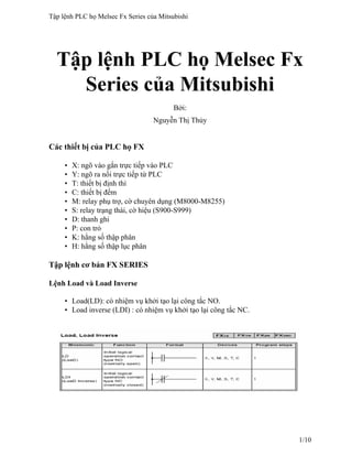
1. Tập lệnh PLC họ Melsec Fx
Series của Mitsubishi
Bởi:
Nguyễn Thị Thủy
Các thiết bị của PLC họ FX
• X: ngõ vào gắn trực tiếp vào PLC
• Y: ngõ ra nối trực tiếp từ PLC
• T: thiết bị định thì
• C: thiết bị đếm
• M: relay phụ trợ, cờ chuyên dụng (M8000-M8255)
• S: relay trạng thái, cờ hiệu (S900-S999)
• D: thanh ghi
• P: con trỏ
• K: hằng số thập phân
• H: hằng số thập lục phân
Tập lệnh cơ bản FX SERIES
Lệnh Load và Load Inverse
• Load(LD): có nhiệm vụ khởi tạo lại công tắc NO.
• Load inverse (LDI) : có nhiệm vụ khởi tạo lại công tắc NC.
Tập lệnh PLC họ Melsec Fx Series của Mitsubishi
1/10
2. Lệnh OUT
• Điều khiển cuộn dây.
• Nhiều lệnh OUT có thể được nối song song.
Lệnh AND và AND INVERSE
• AND: Nối tiếp nhiều công tắc NO, có thể nối tiếp nhiều công tắc cùng một lúc.
• ANI (AND INVERSE): Nối tiếp nhiều công tắc NC, có thể nối tiếp nhiều công
tắc cùng một lúc.
Lệnh OR, OR INVERSE
• OR: Nối song song các công tắc NO, tối đa là 10 nhánh nối song song cho một
cuộn dây.
• ORI (OR INVERSE): OR : Nối song song các công tắc NC, tối đa là 10 nhánh
nối song song cho một cuộn dây.
Tập lệnh PLC họ Melsec Fx Series của Mitsubishi
2/10
3. Lệnh Load Pulse and Load Trailing pulse
• LDP (Load Pulse): hoạt động khi có xung chuyển từ OFF sang ON
• LDF ( Load Falling Pulse): hoạt động khi có xung chuyển từ ON sang OFF
Lệnh And Pulse, And Trailing Pulse
• Lệnh ANDP (And Pulse) hoạt dộng khi có xung chuyển từ trạng thái OFF sang
ON.
• Lệnh ANDF (And Falling Pulse) hoạt động khi có xung chuyển từ trạng thái
ON sang OFF.
• Lệnh ANDP và ANDF sử dùng tương tự lệnh AND và ADNI.
Tập lệnh PLC họ Melsec Fx Series của Mitsubishi
3/10
4. Lệnh OR Pulse ,OR Trailling Pulse
• Lệnh ORP( OR Pulse) hoạt dộng khi có xung chuyển từ trạng thái OFF sang
ON.
• Lệnh ORF (OR Falling Pulse) hoạt độnh khi có xung chuyển từ trạng thái ON
sang OFF.
• Lệnh ORP và ORF sử dùng tương tự lệnh AND và ADNI.
Lệnh Set và Reset
Đặc điểm: SET và RESET có thể dùng cho cùng một thiết bị bao nhiêu lần tùy ý. Tuy
nhiên trạng thái cuối cùng mới là trạng thái tác động.
Tập lệnh PLC họ Melsec Fx Series của Mitsubishi
4/10
5. Nhận xét:
●Khi X0 đã bật ON thì Y0 hoạt động và duy trì trạng thái ON ngay cả khi X0 đã tắt
OFF.
●Khi X1 bật ON thì Y0 sẽ OFF và duy trì trạng thái OFF ngay cả sau khi X1 tự nó
chuyển thành OFF.
●Quá trình xảy ra tương tự cho các M0, D0, S0.
Lệnh Timer, Counter (Out and Reset)
Dạng chung OUT và RESET của timer và Counter :
• OUT: Điều khiển cuộn dây bộ định thời hoặc bộ đếm
• RST(Reset): Đặt lại giá trí tác động cho bộ định thời hoặc bộ đếm.
Hoạt động của bộ định thì và bộ đếm :
Tập lệnh PLC họ Melsec Fx Series của Mitsubishi
5/10
6. Bộ định thì (Timer)
• Các bộ định thì hoạt động bằng cách đếm các xung clock. Ngõ ra của Timer
được kích hoạt khi giá trị đếm được đạt đến giá trị hằng số K. Khoảng thời gian
trôi qua được tính bằng cách lấy giá trị đếm được nhân với độ phân giải của
Timer.
Timer 10 ms đếm giá trị 100 khi đó khoảng thời gian trôi qua được tính như sau:
100*10ms= 100*0.01s= 1s
• Khoảng thời gian định thì được đặt trực tiếp thông qua hằng số K, hoặc gián
tiếp qua thanh ghi dữ liệu D. Thường dùng thanh ghi dữ liệu được chốt để đảm
bảo không bị mất dữ liệu khi mất điện. Tuy nhiên nếu điện áp của nguồn Pin
giảm quá mức thì thời gian định thì có thể bị sai.
Bộ đếm (Counter)
●Khi dùng Counter hằng số K xác định số cần đếm.
Counter với hằng số K10 sẽ phải được kích 10 lần trước khi cuộn dây Counter có điện.
Lệnh END
• Khi đặt tên END trong chương trình có tác dụng buộc kết thúc quá trình quét
chương trình hiện hành và tiến hành cập nhật các ngõ vào/ra, các bộ định thời.
Tập lệnh PLC họ Melsec Fx Series của Mitsubishi
6/10
7. Thực hiện cập nhật các ngõ vào ở đầu chu kỳ quét và cập nhật các ngõ ra ở cuối
chu kỳ quét.
• Việc quét chương trình là quá trình xử lý từng lệnh trong chương trình từ đầu
đến cuối. Khoảng thời gian này gọi là thời gian quét, phụ thuộc vào độ dài và
sự phức tạp của chương trình. Ngay khi dòng quét hiện hành được hoàn tất thì
dòng quét tiếp theo sẽ bắt đầu ngay. Toàn bộ quá trình là một chu kỳ liên tục.
Tập lệnh nâng cao của FX SERIES
Nhóm lệnh điều khiển lưu trình
Lệnh CJ :
Cấu trúc lệnh:
• Chức năng: nhảy tới một vị trí con trỏ đích đã định trước.
• Hoạt động : khi lệnh CJ được thực thi thì nó buộc chương trình nhảy đến vị trí
đã xác định bởi con trỏ đích, có nghĩa là chương trình sẽ bỏ qua các lệnh từ sau
lệnh CJ đến vị trí con trỏ đích.
• Nhiều lệnh CJ có thể dùng cùng một con trỏ đích.
• Bất kỳ đoạn chương trình nào bị bỏ qua thì trạng thái ngõ ra sẽ không được cập
nhật ngay cả khi ngõ vào thay đổi trạng thái.
• Các bộ định thì và bộ đếm sẽ được cố định giá trị hiện hành nếu chúng bị bỏ
qua bởi lệnh CJ.
• Các bộ đếm tốc độ cao là ngoại lệ vì chúng hoạt động độc lập với chương trình
chính.
• Lệnh CJ có thể nhảy đến bất kỳ vị trí nào trong chương trình chính hoặc sau
lệnh FEND.
• Lệnh FEND dùng để chỉ ra điểm kết thúc đầu tiên của chương trình chính để sử
dụng cho chương trình con.
Lệnh CALL:
Tập lệnh PLC họ Melsec Fx Series của Mitsubishi
7/10
8. Cấu trúc lệnh :
• Chức năng: gọi chương trình con hoạt động.
• Hoạt động: khi lệnh CALL được thực thi nó sẽ buộc chương trình chạy chương
trình con được xác định bởi con trỏ đích.
• Lệnh CALL phải được dùng với lệnh FEND và SRET.
• Lệnh SRET có chức năng kết thúc chương trình con hiện hành, trở về bước
ngay sau lệnh CALL vừa được thực thi .
• Nhiều lệnh CALL có thể cùng truy xuất đến một chương trình con.
• Các chương trình con có thể có 5 mức lồng nhau (kể cả mức đầu tiên).
Nhóm lệnh So sánh
Lệnh compare :
Hoạt động: dữ liệu của S1 được so sánh với dữ liệu của S2, kết quả được trả về trong 3
bit có địa chỉ đầu là D.
• Nếu S2 nhỏ hơn S1 thì D = On
• Nếu S2 bằng S1 thì D+1 = On
• Nếu S2 lớn hơn S1 thì D+2 = On
Tập lệnh PLC họ Melsec Fx Series của Mitsubishi
8/10
9. Lệnh zone compare :
Hoạt động: dữ liệu của S3 được so sánh với dãy dữ liệu (S1, S2).
• Nếu S3 nhỏ hơn (S1, S2) thì D = On
• Nếu S3 thuộc (S1, S2) thì D+1 = On
• Nếu S3 lớn hơn (S1, S2) thì D+2 = On
Lệnh MOV
Hoạt động: dữ liệu của thiết bị nguồn S được sao chép đến thiết bị đích D.
Lệnh XCH
Hoạt động: dữ liệu của hai thiết bị đích D1 và D2 được hoán đổi cho nhau.
Lệnh BCD
Hoạt động: dữ liệu nhị phân trong thiết bị nguồn S được chuyển đổi sang số BCD tương
ứng và lưu trong thiết bị đích D.
Tập lệnh PLC họ Melsec Fx Series của Mitsubishi
9/10
10. Lệnh BIN
Hoạt động: dữ liệu nhị phân trong thiết bị nguồn S được chuyển đổi sang số BCD tương
ứng và lưu trong thiết bị đích D.
Tập lệnh PLC họ Melsec Fx Series của Mitsubishi
10/10