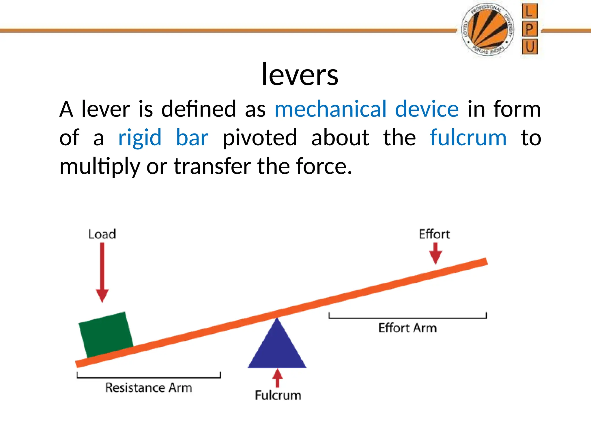
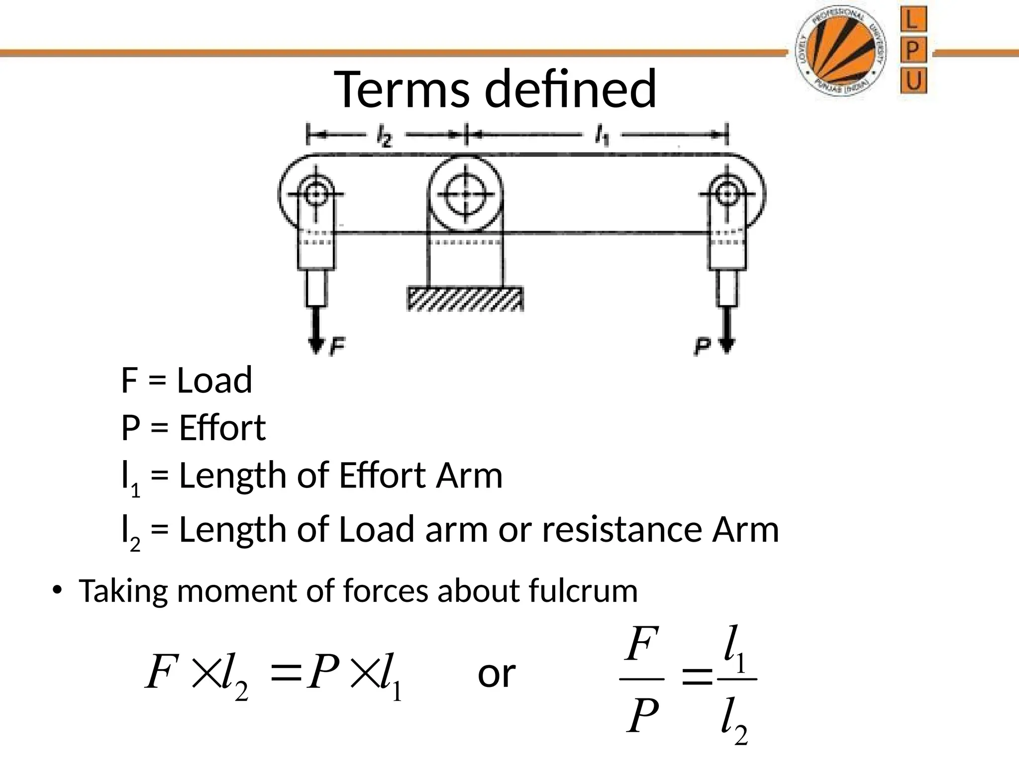
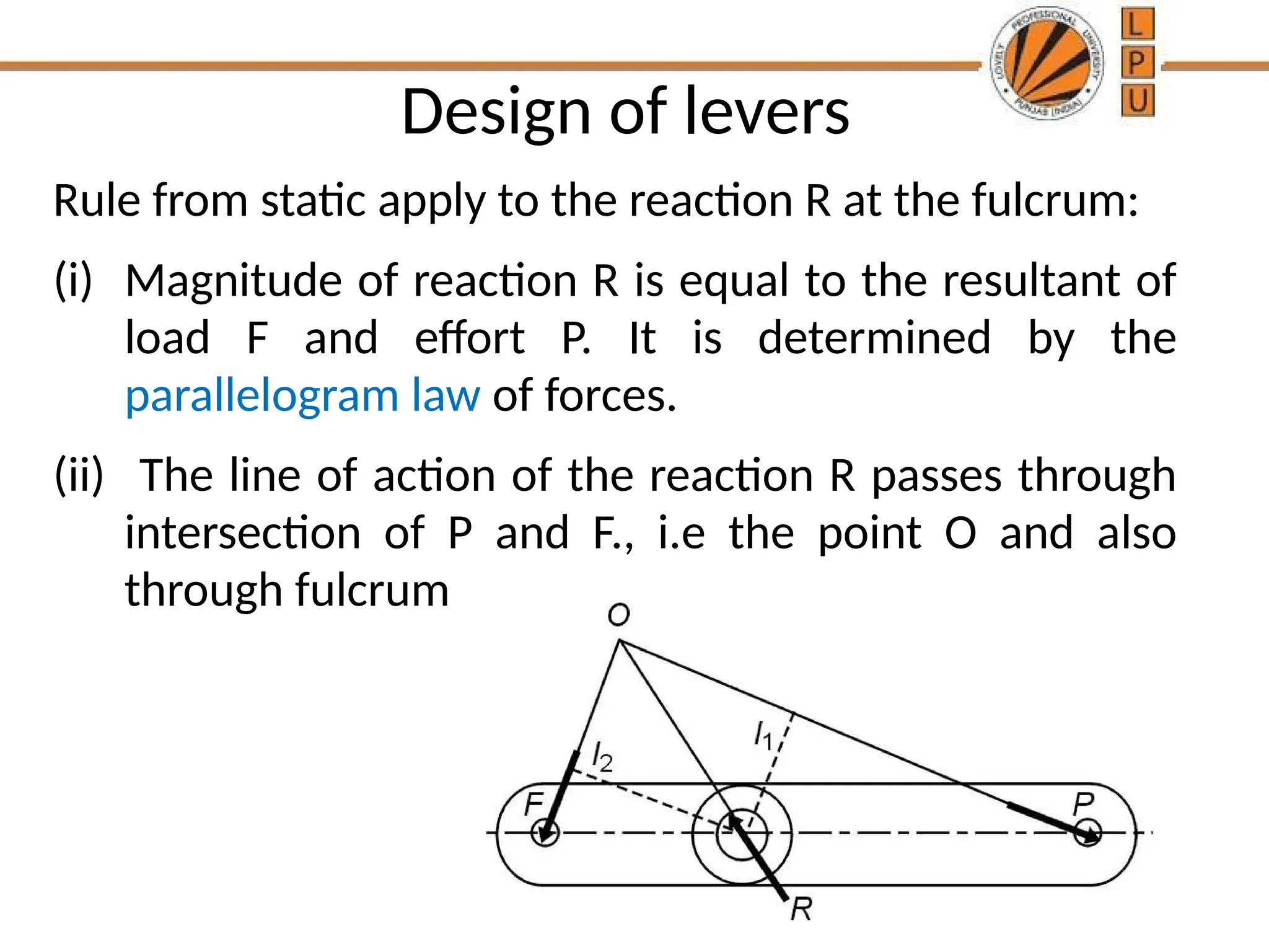
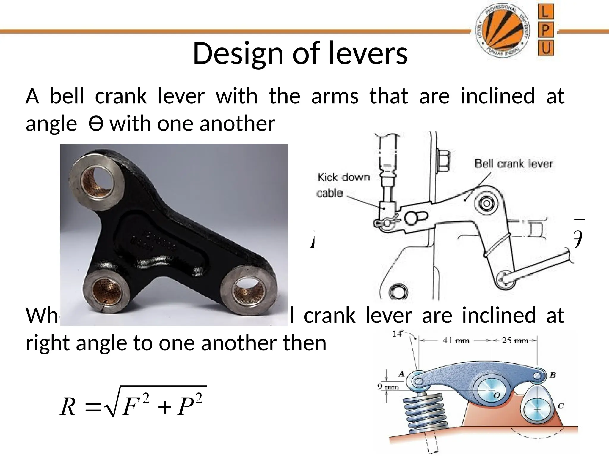
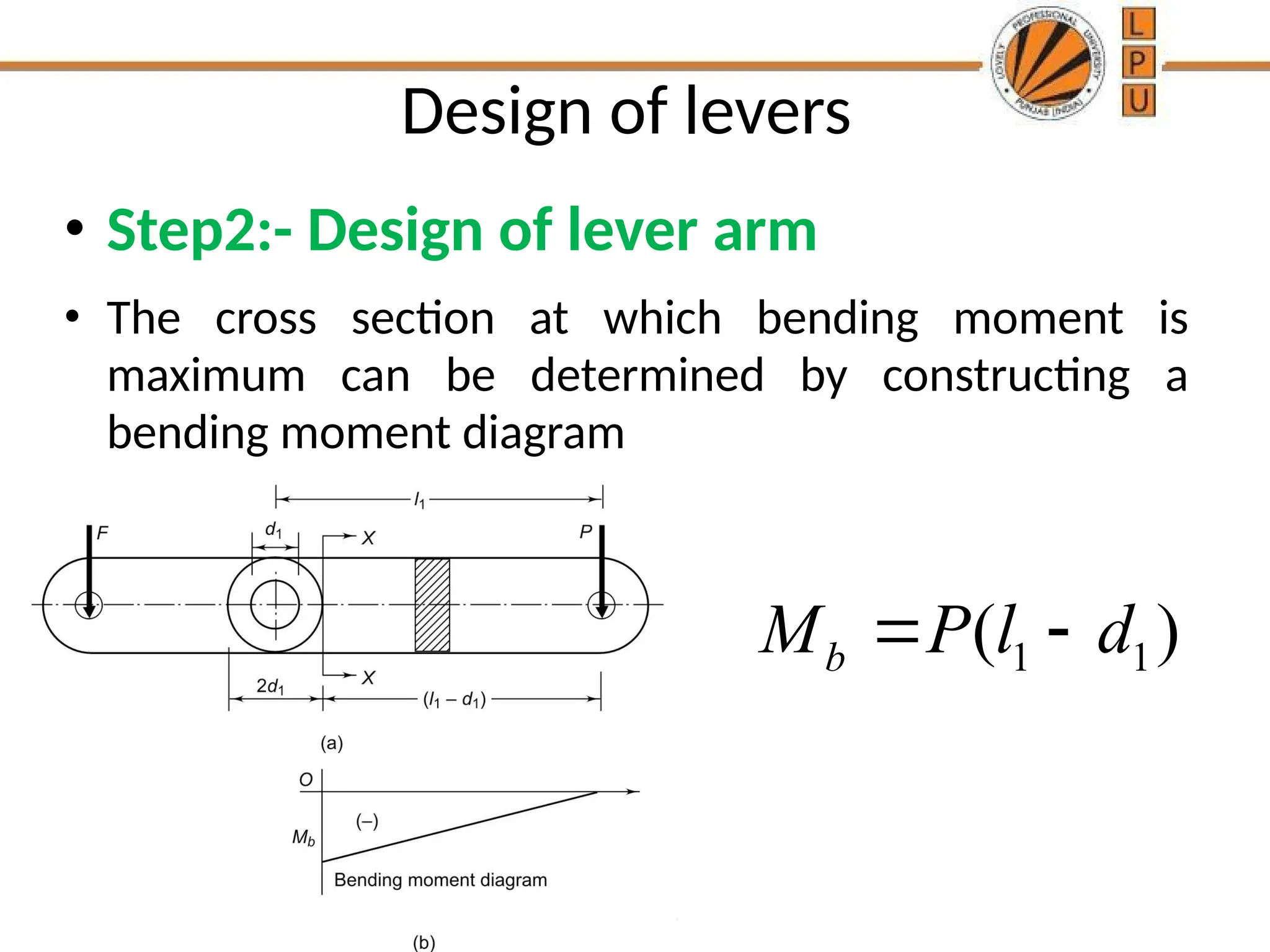
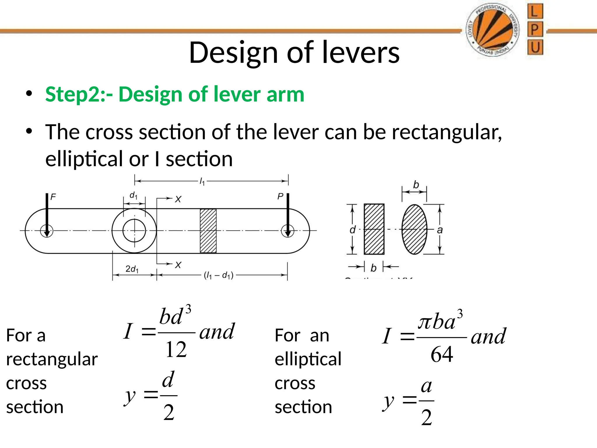
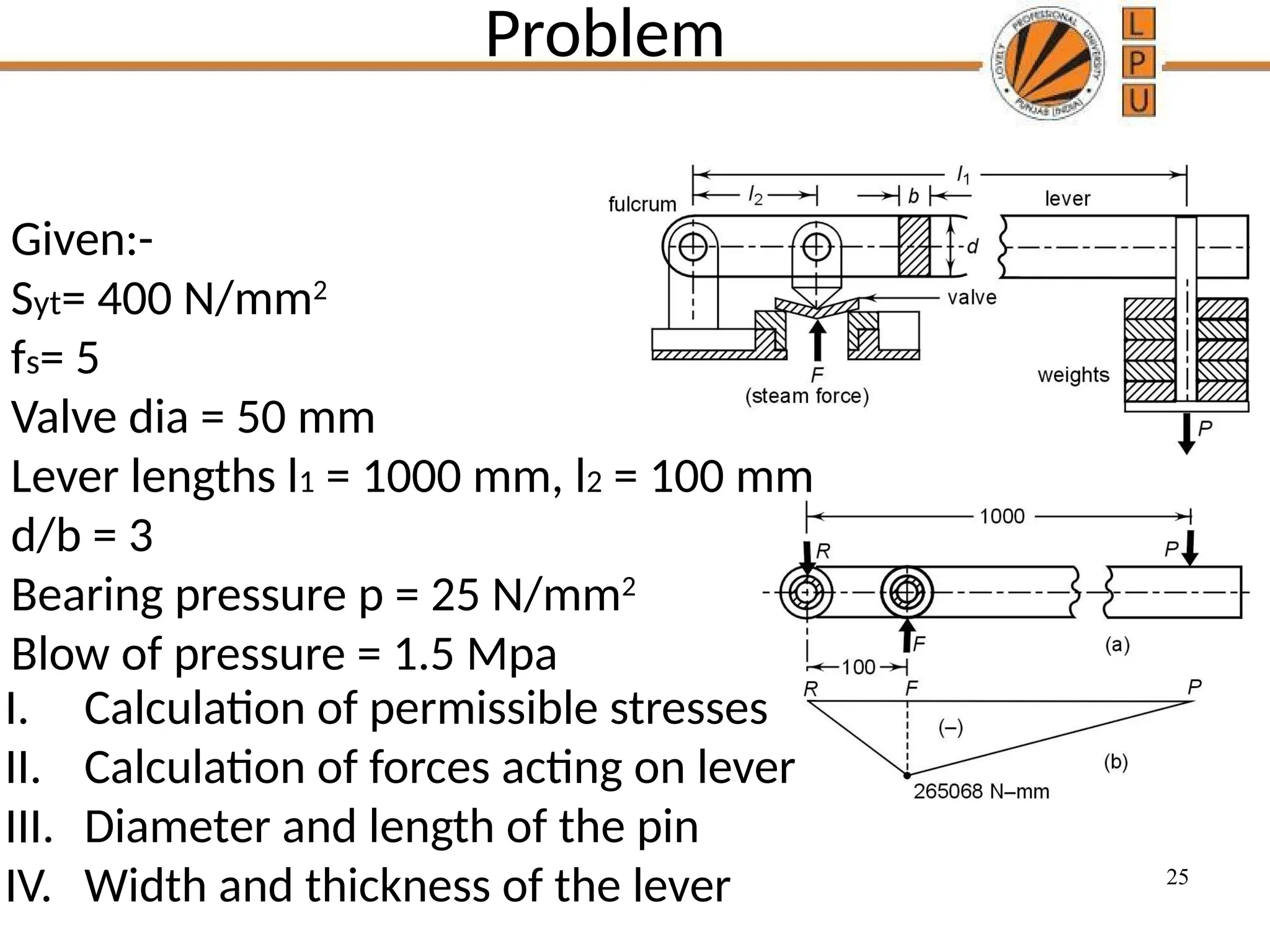
MEC223
Design of Machine Element -I
2
• GIVE ME A PLACE TO STAND AND I
WILL MOVE THE EARTH
3
“Give me a lever long enough and a
fulcrum on which to place it, and I shall
move the world.”
levers
A lever is defined as mechanical device in form
of a rigid bar pivoted about the fulcrum to
multiply or transfer the force.
Terms defined
• Taking moment of forces about fulcrum
F = Load
P = Effort
l1 = Length of Effort Arm
l2 = Length of Load arm or resistance Arm
2 1
F l P l
   1
2
l
F
P l

or
6
Mechanical Advantage and Leverage
• The Ratio F/P is called the ‘mechanical advantage’
• The Ratio l1/l2 is called the ‘leverage’
Types of levers
8
2ND
CLASS LEVER
9
3RD
CLASS LEVER
10
Types of levers
When l1<l2 (mechanical advantage<1)
When l1=l2 ( mechanical advantage=1)
When l1>l2 ( mechanical advantage>1)
The Ratio l1/l2 is called the ‘leverage’
Design of levers
• Lever is easy compared with the design of other
machine elements.
• The length of the lever is decided on the basis of
leverage required to exert a given load F by means of
an effort P.
• The cross section of lever is designed on the basis of
bending stress.
Design of levers
• Step 1: Force analysis:- The effort required to
produce the force is calculated by taking moments
about the fulcrum
• R is the reaction at the fulcrum pin. Since the sum of vertical
forces acting on the lever must be equal to zero
R=F+P
Design of levers
Second type:-In this type of lever force F(Load) and
P(Effort) act in opposite direction.
F R P
or
R F P
 
 
Design of levers
• If forces F and P act along lines that are inclined to
one another.
• In such cases, l1 is the perpendicular distance from
the fulcrum to line of action of the force P.
• Similarly, l2 is the perpendicular distance from fulcrum
to the line of action of force F.
Design of levers
Rule from static apply to the reaction R at the fulcrum:
(i) Magnitude of reaction R is equal to the resultant of
load F and effort P. It is determined by the
parallelogram law of forces.
(ii) The line of action of the reaction R passes through
intersection of P and F., i.e the point O and also
through fulcrum
Design of levers
A bell crank lever with the arms that are inclined at
angle Ө with one another
When the arms of the bell crank lever are inclined at
right angle to one another then
2 2
R F P
 
2 2
2 cos
R F P FP 
  
Design of levers
• Step2:- Design of lever arm
• The cross section at which bending moment is
maximum can be determined by constructing a
bending moment diagram
1 1
( )
b
M P l d
 
Design of levers
• Step2:- Design of lever arm
• The cross section of the lever can be rectangular,
elliptical or I section
3
12
2
bd
I and
d
y


For a
rectangular
cross
section
For an
elliptical
cross
section
3
64
2
ba
I and
a
y



Design of levers
• Step2:- Design of lever arm
• Usually
• d = 2b for rectangular cross section and
• a = 2b for elliptical cross section
• Using the above mentioned proportions, the
dimensions of the cross section of the lever can be
determined by
b
b
M y
I
 
Design of fulcrum Pin
• The fulcrum pin is subjected to
reaction R as shown
• The dimensions of the pin are
determined by bearing
consideration and then checked for
shear consideration.
• Where p is the permissible
bearing pressure
• The ratio l/d1 is usually taken
from 1 to 2
P (l X d1)
Design of fulcrum Pin
• A phosphor bronze bush, usually 3 mm thick, is
fitted inside the boss to reduce the friction.
• The permissible bearing pressure for a phosphor
bronze bush is 5 to 10 N/mm2
.
• Expression for bearing pressure
•
p
23
Problem
A lever loaded safety valve is mounted on the boiler
to blow off at a pressure of 1.5 MPa gauge. The
effective diameter of the opening of the valve is 50
mm. The distance between the fulcrum and the dead
weights on the lever is 1000mm. The distance
between the fulcrum and the pin connecting the valve
spindle to the lever is 100 mm. The lever and the pin
are made of plain carbon steel 30C8 (Syt = 400
N/mm2
) and factor of safety is 5 the permissible
bearing pressure at the pins in the lever is 25 N/mm2
.
The lever has a rectangular cross section and the ratio
of width to thickness is 3:1. Design a suitable lever for
the safety valve.
24
Problem
25
Problem
Given:-
Syt= 400 N/mm2
fs= 5
Valve dia = 50 mm
Lever lengths l1 = 1000 mm, l2 = 100 mm
d/b = 3
Bearing pressure p = 25 N/mm2
Blow of pressure = 1.5 Mpa
I. Calculation of permissible stresses
II. Calculation of forces acting on lever
III. Diameter and length of the pin
IV. Width and thickness of the lever
26
27
28
29
30
31

Lecture13-14-MEC223 - Copy.pptxgffffffffffff

  • 1.
  • 2.
    2 • GIVE MEA PLACE TO STAND AND I WILL MOVE THE EARTH
  • 3.
    3 “Give me alever long enough and a fulcrum on which to place it, and I shall move the world.”
  • 4.
    levers A lever isdefined as mechanical device in form of a rigid bar pivoted about the fulcrum to multiply or transfer the force.
  • 5.
    Terms defined • Takingmoment of forces about fulcrum F = Load P = Effort l1 = Length of Effort Arm l2 = Length of Load arm or resistance Arm 2 1 F l P l    1 2 l F P l  or
  • 6.
    6 Mechanical Advantage andLeverage • The Ratio F/P is called the ‘mechanical advantage’ • The Ratio l1/l2 is called the ‘leverage’
  • 7.
  • 8.
  • 9.
  • 10.
  • 11.
    Types of levers Whenl1<l2 (mechanical advantage<1) When l1=l2 ( mechanical advantage=1) When l1>l2 ( mechanical advantage>1) The Ratio l1/l2 is called the ‘leverage’
  • 12.
    Design of levers •Lever is easy compared with the design of other machine elements. • The length of the lever is decided on the basis of leverage required to exert a given load F by means of an effort P. • The cross section of lever is designed on the basis of bending stress.
  • 13.
    Design of levers •Step 1: Force analysis:- The effort required to produce the force is calculated by taking moments about the fulcrum • R is the reaction at the fulcrum pin. Since the sum of vertical forces acting on the lever must be equal to zero R=F+P
  • 14.
    Design of levers Secondtype:-In this type of lever force F(Load) and P(Effort) act in opposite direction. F R P or R F P    
  • 15.
    Design of levers •If forces F and P act along lines that are inclined to one another. • In such cases, l1 is the perpendicular distance from the fulcrum to line of action of the force P. • Similarly, l2 is the perpendicular distance from fulcrum to the line of action of force F.
  • 16.
    Design of levers Rulefrom static apply to the reaction R at the fulcrum: (i) Magnitude of reaction R is equal to the resultant of load F and effort P. It is determined by the parallelogram law of forces. (ii) The line of action of the reaction R passes through intersection of P and F., i.e the point O and also through fulcrum
  • 17.
    Design of levers Abell crank lever with the arms that are inclined at angle Ө with one another When the arms of the bell crank lever are inclined at right angle to one another then 2 2 R F P   2 2 2 cos R F P FP    
  • 18.
    Design of levers •Step2:- Design of lever arm • The cross section at which bending moment is maximum can be determined by constructing a bending moment diagram 1 1 ( ) b M P l d  
  • 19.
    Design of levers •Step2:- Design of lever arm • The cross section of the lever can be rectangular, elliptical or I section 3 12 2 bd I and d y   For a rectangular cross section For an elliptical cross section 3 64 2 ba I and a y   
  • 20.
    Design of levers •Step2:- Design of lever arm • Usually • d = 2b for rectangular cross section and • a = 2b for elliptical cross section • Using the above mentioned proportions, the dimensions of the cross section of the lever can be determined by b b M y I  
  • 21.
    Design of fulcrumPin • The fulcrum pin is subjected to reaction R as shown • The dimensions of the pin are determined by bearing consideration and then checked for shear consideration. • Where p is the permissible bearing pressure • The ratio l/d1 is usually taken from 1 to 2 P (l X d1)
  • 22.
    Design of fulcrumPin • A phosphor bronze bush, usually 3 mm thick, is fitted inside the boss to reduce the friction. • The permissible bearing pressure for a phosphor bronze bush is 5 to 10 N/mm2 . • Expression for bearing pressure • p
  • 23.
    23 Problem A lever loadedsafety valve is mounted on the boiler to blow off at a pressure of 1.5 MPa gauge. The effective diameter of the opening of the valve is 50 mm. The distance between the fulcrum and the dead weights on the lever is 1000mm. The distance between the fulcrum and the pin connecting the valve spindle to the lever is 100 mm. The lever and the pin are made of plain carbon steel 30C8 (Syt = 400 N/mm2 ) and factor of safety is 5 the permissible bearing pressure at the pins in the lever is 25 N/mm2 . The lever has a rectangular cross section and the ratio of width to thickness is 3:1. Design a suitable lever for the safety valve.
  • 24.
  • 25.
    25 Problem Given:- Syt= 400 N/mm2 fs=5 Valve dia = 50 mm Lever lengths l1 = 1000 mm, l2 = 100 mm d/b = 3 Bearing pressure p = 25 N/mm2 Blow of pressure = 1.5 Mpa I. Calculation of permissible stresses II. Calculation of forces acting on lever III. Diameter and length of the pin IV. Width and thickness of the lever
  • 26.
  • 27.
  • 28.
  • 29.
  • 30.
  • 31.