This document discusses T flip-flops and JK flip-flops in the context of a digital logic class at Iowa State University. T flip-flops toggle their state based on their input, while JK flip-flops can function as both SR and T flip-flops depending on their inputs. The document includes circuit diagrams, truth tables, and a brief explanation of how each flip-flop operates.


![[ Figure 5.15a from the textbook ]
T Flip-Flop](https://image.slidesharecdn.com/27tandjkflip-flops-250207203947-55a5b4a8/85/Lecture-digital-27_T_and_JK_Flip-Flops-ppt-6-320.jpg)
![[ Figure 5.15a from the textbook ]
T Flip-Flop
Positive-edge-triggered
D Flip-Flop](https://image.slidesharecdn.com/27tandjkflip-flops-250207203947-55a5b4a8/85/Lecture-digital-27_T_and_JK_Flip-Flops-ppt-7-320.jpg)
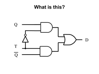
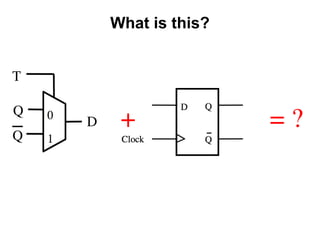
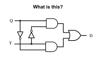
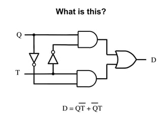
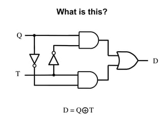
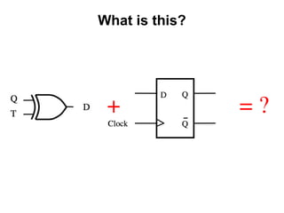
![[ Figure 5.15a from the textbook ]
T Flip-Flop
What is this?](https://image.slidesharecdn.com/27tandjkflip-flops-250207203947-55a5b4a8/85/Lecture-digital-27_T_and_JK_Flip-Flops-ppt-8-320.jpg)


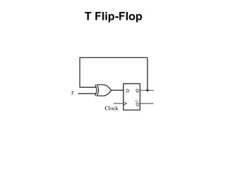

![[ Figure 5.15a,b from the textbook ]
T Flip-Flop
(circuit and truth table)](https://image.slidesharecdn.com/27tandjkflip-flops-250207203947-55a5b4a8/85/Lecture-digital-27_T_and_JK_Flip-Flops-ppt-19-320.jpg)
![[ Figure 5.15a,c from the textbook ]
T Flip-Flop
(circuit and graphical symbol)](https://image.slidesharecdn.com/27tandjkflip-flops-250207203947-55a5b4a8/85/Lecture-digital-27_T_and_JK_Flip-Flops-ppt-20-320.jpg)
![[ Figure 5.15d from the textbook ]
T Flip-Flop (Timing Diagram)](https://image.slidesharecdn.com/27tandjkflip-flops-250207203947-55a5b4a8/85/Lecture-digital-27_T_and_JK_Flip-Flops-ppt-21-320.jpg)

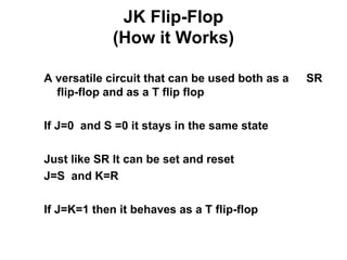
![[ Figure 5.16a from the textbook ]
JK Flip-Flop
D = JQ + KQ](https://image.slidesharecdn.com/27tandjkflip-flops-250207203947-55a5b4a8/85/Lecture-digital-27_T_and_JK_Flip-Flops-ppt-23-320.jpg)
![[ Figure 5.16 from the textbook ]
JK Flip-Flop
J Q
Q
K
0
1
Q t 1
+
Q t
0
(b) Truth table (c) Graphical symbol
J
0
0
0 1
1
1 Q t
1
K
D Q
Q
Q
Q
J
Clock
(a) Circuit
K](https://image.slidesharecdn.com/27tandjkflip-flops-250207203947-55a5b4a8/85/Lecture-digital-27_T_and_JK_Flip-Flops-ppt-24-320.jpg)