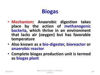
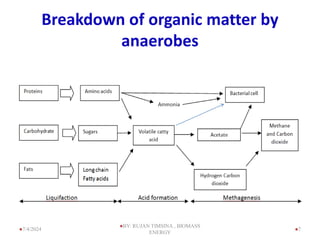
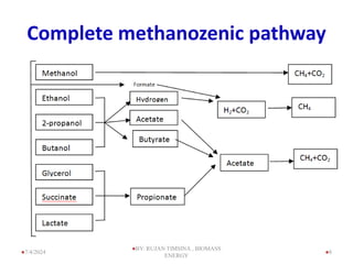
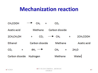
Rujan Timsina
Biogas
Bio energy
2
• The word 'Biomass' is a very comprehensive term
comprising of all forms of matter derived from
biological activities and are present either on the
surface of the soil or at different depths of vast body
of water, lakes, streams, river, seas, ocean etc.
7/4/2024
BY: RUJAN TIMSINA , BIOMASS
ENERGY
Bio energy
• Biomass production varies with local conditions,
and is about twice as greater per unit surface
area on land than at sea.
• 43% of the energy used by the third world
country is derived from biomass.
• 2.4 billion people are totally reliant on biomass
fuels for their energy needs.
• Yet only 14% of the world's energy comes from
biomass.
• If biomass is to be considered renewable, growth
must at least keep pace with use.
Forms of bioenergy
• Gaseous ( methane, bio hydrogen)
• Liquid ( Ethanol, butanol, Bioethanol,
Biodiesel , Biobutanol, Biohydro carbon oil,
Algae biofuel )
• Solid (Wood, briquette, pellate )
4
7/4/2024
BY: RUJAN TIMSINA , BIOMASS
ENERGY
Biogas
5
7/4/2024
BY: RUJAN TIMSINA , BIOMASS
ENERGY
Biogas
• Mechanism: Anaerobic digestion takes
place by the action of methanogenic
bacteria, which thrive in an environment
that lacks air (oxygen) but has favorable
temperature
• Also known as a bio-digester, bioreactor or
anaerobic reactor
• Complete biogas production unit is termed
as biogas plant
6
7/4/2024
BY: RUJAN TIMSINA , BIOMASS
ENERGY
Breakdown of organic matter by
anaerobes
7
7/4/2024
BY: RUJAN TIMSINA , BIOMASS
ENERGY
Complete methanozenic pathway
8
7/4/2024
BY: RUJAN TIMSINA , BIOMASS
ENERGY
Mechanization reaction
9
7/4/2024
BY: RUJAN TIMSINA , BIOMASS
ENERGY
Component of biogas plant
• Digestion Chamber: Chamber where
anaerobic condition is ensured and organic
matter is digested by methanogenic bacteria
should be air tight
• Inlet: to feed organic matter into digestion
chamber
• Outlet: to remove digested matter, i.e., slurry
10
7/4/2024
BY: RUJAN TIMSINA , BIOMASS
ENERGY
jfof]UofF;
11
7/4/2024
BY: RUJAN TIMSINA , BIOMASS
ENERGY
Biogas - Methane
Burns with a clean blue flame
similar to LPG
By product: water & CO2
Chemical Equation
CH4 + 2O22H2O + CO2
CDM – Carbon credit:
CH4 is 20 times more harmful
than CO2 in terms of
greenhouse gas effects
12
7/4/2024
BY: RUJAN TIMSINA , BIOMASS
ENERGY
LPG & Biogas
Biogas
LPG
 LPG: can be compressed, Methane: non compressible gas
 Thus, storage of biogas is not feasible
 Energy content: LPG = 44 MJ/kg, Biogas = 20 MJ/m3
- Stove efficiency: LPG = 53%, Biogas = 44%
13
7/4/2024
BY: RUJAN TIMSINA , BIOMASS
ENERGY
Factors affecting for the biogas
production
14
7/4/2024
BY: RUJAN TIMSINA , BIOMASS
ENERGY
C/N Ratio
• C/N Ratio: Ratio of carbon to nitrogen present
in the organic matter.
• Gas production optimum @ C/N ratio 20 - 30.
C/N ratio of cow/buffalo dung ~ 25 and hence
ideal for biogas production.
• C/N ratio can be brought within the optimum
range by mixing different inputs (in certain
ratios).
15
7/4/2024
BY: RUJAN TIMSINA , BIOMASS
ENERGY
C/N Ratio
• C/N Ratio of some organic matter
S. N. Raw Materials C/N Ratio
1. Chicken dung 10
2. Human excreta 8
3. Goat dung 12
4. Pig dung 18
5. Sheep dung 19
6. Cow/ buffalo dung 24
7. Elephant dung 43
8. Water hyacinth 25
9. Straw (Maize, Rice, wheat) 60, 70, 90
10. Saw dust Above 200
16
7/4/2024
BY: RUJAN TIMSINA , BIOMASS
ENERGY
pH
• Optimum gas production occurs when the pH
value of the input is 6 – 7.
Volatile acids
• Avetic acids, propionic aics etc. give actual
situation inside the plant
17
7/4/2024
BY: RUJAN TIMSINA , BIOMASS
ENERGY
Digestion temperature
• Optimum gas production: 35oC. Below 20oC gas
production is significantly reduced
• If the ambient temperature is 10oC or lower, gas
production stops. Even a sudden fall of temperature
by 2 to 3oC significantly reduces gas production.
• increase gas production in the cold climates by
– Insulation
– External heating
18
7/4/2024
BY: RUJAN TIMSINA , BIOMASS
ENERGY
Retention time
• Is a function of the type of input and the ambient
temperature. For cow/buffalo dung input BSP recommends a
retention time of 70 days in the hills and 55 days in the Terai
(warmer climate).
• Loading rates: 7.5 kg of cow dung per m3 plant size per day in
Terai and 6 kg in the hills. E.g. 4 m3 plant  loading rate = 24
kg/day dung input in hills & 30 kg/day in Terai
• Since human excreta contain more pathogens (disease
vectors) than most animal dung, 90 – 100 days retention time
is recommended
19
7/4/2024
BY: RUJAN TIMSINA , BIOMASS
ENERGY
Consistency
• Consistency: dung-water ratio
- If too thick, it will settle at the bottom of digester
and be pushed out by gas pressure before being
completely digested.
- If is too thin, additional dead space in the
digester chamber is occupied by water.
• In case of cow/buffalo dung for a given volume of
fresh input an equal volume of water is added and
the slurry is well mixed i.e., 1:1 Ratio.
20
7/4/2024
BY: RUJAN TIMSINA , BIOMASS
ENERGY
Gas production potential of
various types of dung
S.N. Types of Dung Gas production per kg dung
(m3)
1. Cattle (Cows and
buffaloes)
0.023 - 0.040
2. Pig 0.040 - 0.059
3. Poultry (Chickens) 0.065-0.116
4. Human 0.020- 0.028
Updated Guidebook on Biogas Development, 1984
21
7/4/2024
BY: RUJAN TIMSINA , BIOMASS
ENERGY
Main Sources of biogas production
• Landfill sites
• Wastewater treatment
• Co-digestion of manure
• Other sources
22
7/4/2024
BY: RUJAN TIMSINA , BIOMASS
ENERGY
Different Sizes of Plant
23
7/4/2024
BY: RUJAN TIMSINA , BIOMASS
ENERGY
24
7/4/2024
BY: RUJAN TIMSINA , BIOMASS
ENERGY
Biogas plant
• The success or failure of any biogas plant mainly
depends upon the quality of construction works.
• The mason should be with respect to the
dimensions as indicated on the drawing
• Follow the correct construction method
25
7/4/2024
BY: RUJAN TIMSINA , BIOMASS
ENERGY
Construction Materials
• Cement
• Sand
• Gravel
• Water
• Bricks
• Stones
26
7/4/2024
BY: RUJAN TIMSINA , BIOMASS
ENERGY
Construction Site Selection
• Sun site
• The plant must be as close as possible to cattle shed and water
source
• For water source is at a distance of more than 20 minutes walk, no
plant should be installed in such places.
• Longer gas-pipe increase cost and risk of gas leakage due to more
joints in it.
• The main valve has to be opened and closed before and after use
so the plant should be as close as possible
• The edge of the foundation of the plant should be at least two
meters away from the house
• The plant should be at least 10 metres away from the well or any
other under ground water sources to protect water from pollution
• Safe from roots of trees & bamboo
. 27
7/4/2024
BY: RUJAN TIMSINA , BIOMASS
ENERGY
Digging and Pit Depth
28
7/4/2024
BY: RUJAN TIMSINA , BIOMASS
ENERGY
Construction of Biogas Plant GGC 2047
29
7/4/2024
BY: RUJAN TIMSINA , BIOMASS
ENERGY
Construction of round wall
8fOh]:6/ / kvf{nsf]
9nfg sfd
30
7/4/2024
BY: RUJAN TIMSINA , BIOMASS
ENERGY
Construction of Biogas Plant
8fO{h]:6/sf] 8f]dsf] lgdf{0f
31
7/4/2024
BY: RUJAN TIMSINA , BIOMASS
ENERGY
Construction Outlet Chamber
• To construct the outlet tank, excavation has to be
done just behind the manhole.
• The outlet tank should be on a slightly higher
elevation than the surrounding so that there are no
chances of water running into the outlet during the
rainy season.
• Concrete slabs for the
outlet should be constructed
32
7/4/2024
BY: RUJAN TIMSINA , BIOMASS
ENERGY
Construction of Inlet Pit
• Constructed to mix dung and water.
• Constructed with or without a mixing device
• The top of the structure should not be more than one meter
high from the ground level and both inside and outside of
the pit has to be covered with a smooth layer of plaster (Mix:
1 cement-3 sand).
• The bottom of the tank must be at least 5 cm above the
outlet overflow level.
33
7/4/2024
BY: RUJAN TIMSINA , BIOMASS
ENERGY
Construction of Inlet Pit
• Toilet attachment to the plant it is better to construct
without siphon or trap as the pan with siphon needs more
water which may result excess water inside the digester.
• The toilet should not be farther than 45 degrees from the
hart line.
• Toilet pan level should be at
least 25 cm above the
outlet overflow level
34
7/4/2024
BY: RUJAN TIMSINA , BIOMASS
ENERGY
Lay-out of Pipeline
• buried 1 foot below ground level.
• reduce the risk of leakage,
• The biogas coming from the digester is saturated with
water vapor. This water vapor will condense at the walls of
the pipeline, a water drain has to be placed in the pipeline.
• The position of the water drain should be vertically below
the lowest point of the pipeline so that water will flow by
gravity to the trap.
35
7/4/2024
BY: RUJAN TIMSINA , BIOMASS
ENERGY
Lay-out of Pipeline
• For connecting burners with gas pipelines, use of
transparent polyethylene hose must be avoided. Only
neoprene rubber hose of the best quality should be used.
• As soon as there is gas production, all joints and taps must
be checked for leakage by applying a thick soap solution. If
there is leakage the foam will either move or break
36
7/4/2024
BY: RUJAN TIMSINA , BIOMASS
ENERGY
Compost Pits
• A minimum of 2 compost pits must be dug near to the
outlet overflow in such a way that the slurry can run
freely into the pits.
• For proper insulation during the cold season and as
counter weight against the gas pressure inside, a
minimum top filling of 40 cm compacted earth is required
on the dome.
37
7/4/2024
BY: RUJAN TIMSINA , BIOMASS
ENERGY
38
7/4/2024
BY: RUJAN TIMSINA , BIOMASS
ENERGY
Type of digesters
Floating Drum Digester
- Experiments in India began in 1930’s
- In 1956 J.S. Patel developed the model
- Also known as KVIC mode
• Digester made of brick masonry
• Mild steel drum placed on top for gas
collection which moves up & down
• drum level indicates volume of gas in
the plant
• Problem: Corrosion of MS drum
39
7/4/2024
BY: RUJAN TIMSINA , BIOMASS
ENERGY
Fixed Dome Digester
• GGC model:
- Similar to the Chinese fixed dome
model but simpler to construct
e.g., flat bottom, less curves
• Eliminates need for costlier MS
gasholder which corrodes with
time
• Useful Life: 20 – 50 years
• no corrosion problem GGC Model
40
7/4/2024
BY: RUJAN TIMSINA , BIOMASS
ENERGY
Puxin biogas Technology
outlet
inlet
Gas holder
Gas digester
cover
neck
41
7/4/2024
BY: RUJAN TIMSINA , BIOMASS
ENERGY
Introduction
• To renovate the traditional biogas plant Shenzhen
Puxin Science & Technology Co. through many
year’s study has developed a new generational
hydraulic biogas Plant called Puxin Biogas Plant.
• This biogas plant can be taken as daily feeding, semi-
batch and batch feeding plant (the three types of biogas
plants practiced around the world).
• The Puxin Biogas Plant is composed of a concrete
based digester and the fiber glass reinforced gas holder
with high efficient biogas appliances
42
7/4/2024
BY: RUJAN TIMSINA , BIOMASS
ENERGY
1. Concrete Digester
• The stomach (digester) of the plant is made with the help
of scaffolding (steel mould) by casting the concrete 1:3:3(
cement, smashed stone, sand).
• The volume of digester varies according to frame . The
basic sizes Puxin biogas plants are of 6 cu.m. and 10 cu.m.
2. Neck
• The round part above the Digester is known as
neck.
• This is also made with the help of steel frame.
• The neck is essential for fixing the gas holder.
• The water level above the gas holder in the neck
determines the pressure of gas.
43
7/4/2024
BY: RUJAN TIMSINA , BIOMASS
ENERGY
CASTING OF CONCRETE DIGESTER WITH THE HELP OF STEEL MOULD
(SCAFFOLDING)
44
7/4/2024
BY: RUJAN TIMSINA , BIOMASS
ENERGY
CASTING OF CONCRETE DIGESTER WITH THE HELP OF STEEL MOULD
(SCAFFOLDING)
45
7/4/2024
BY: RUJAN TIMSINA , BIOMASS
ENERGY
3. Gas Holder:
– The gas holder is made up of reinforced glass fiber, which
is 100% air and water tight.
– The gas holder always remains below the water level and is
fixed in the neck part of the plant.
– On the top of the gasholder there is a valve. When needed,
the valve can be opened to relieve the atmospheric pressure
– The gas pipe outlet is from the middle part of the gas
holder.
46
7/4/2024
BY: RUJAN TIMSINA , BIOMASS
ENERGY
4. Inlet and outlet:
• The inlet is for feeding materials into the plant and
the outlet is to help to flow out slurry to drainage
5. Covers:
• The neck is covered
with five concrete
covers (slabs)
• The inlet and outlet
is also covered with
slab of suitable sizes.
47
7/4/2024
BY: RUJAN TIMSINA , BIOMASS
ENERGY
48
7/4/2024
BY: RUJAN TIMSINA , BIOMASS
ENERGY
Function and Operation
49
When biogas
produces, it will
displace the
water from gas
collector and
water level
rises at inlet ,
outlet and
above the gas
holder.
7/4/2024
BY: RUJAN TIMSINA , BIOMASS
ENERGY
50
• When holder completely
fill by gas then gas will
escape through the lower
part of the gas holder
• When gas level decrease,
than water will enter into
the gas holder and water
level also decrease on
inlet, outlet and above the
gas holder
7/4/2024
BY: RUJAN TIMSINA , BIOMASS
ENERGY
Thank you
51
7/4/2024
BY: RUJAN TIMSINA , BIOMASS
ENERGY

Lecture 3 Biomass energy...............ppt

  • 1.
  • 2.
    Bio energy 2 • Theword 'Biomass' is a very comprehensive term comprising of all forms of matter derived from biological activities and are present either on the surface of the soil or at different depths of vast body of water, lakes, streams, river, seas, ocean etc. 7/4/2024 BY: RUJAN TIMSINA , BIOMASS ENERGY
  • 3.
    Bio energy • Biomassproduction varies with local conditions, and is about twice as greater per unit surface area on land than at sea. • 43% of the energy used by the third world country is derived from biomass. • 2.4 billion people are totally reliant on biomass fuels for their energy needs. • Yet only 14% of the world's energy comes from biomass. • If biomass is to be considered renewable, growth must at least keep pace with use.
  • 4.
    Forms of bioenergy •Gaseous ( methane, bio hydrogen) • Liquid ( Ethanol, butanol, Bioethanol, Biodiesel , Biobutanol, Biohydro carbon oil, Algae biofuel ) • Solid (Wood, briquette, pellate ) 4 7/4/2024 BY: RUJAN TIMSINA , BIOMASS ENERGY
  • 5.
  • 6.
    Biogas • Mechanism: Anaerobicdigestion takes place by the action of methanogenic bacteria, which thrive in an environment that lacks air (oxygen) but has favorable temperature • Also known as a bio-digester, bioreactor or anaerobic reactor • Complete biogas production unit is termed as biogas plant 6 7/4/2024 BY: RUJAN TIMSINA , BIOMASS ENERGY
  • 7.
    Breakdown of organicmatter by anaerobes 7 7/4/2024 BY: RUJAN TIMSINA , BIOMASS ENERGY
  • 8.
  • 9.
  • 10.
    Component of biogasplant • Digestion Chamber: Chamber where anaerobic condition is ensured and organic matter is digested by methanogenic bacteria should be air tight • Inlet: to feed organic matter into digestion chamber • Outlet: to remove digested matter, i.e., slurry 10 7/4/2024 BY: RUJAN TIMSINA , BIOMASS ENERGY
  • 11.
  • 12.
    Biogas - Methane Burnswith a clean blue flame similar to LPG By product: water & CO2 Chemical Equation CH4 + 2O22H2O + CO2 CDM – Carbon credit: CH4 is 20 times more harmful than CO2 in terms of greenhouse gas effects 12 7/4/2024 BY: RUJAN TIMSINA , BIOMASS ENERGY
  • 13.
    LPG & Biogas Biogas LPG LPG: can be compressed, Methane: non compressible gas  Thus, storage of biogas is not feasible  Energy content: LPG = 44 MJ/kg, Biogas = 20 MJ/m3 - Stove efficiency: LPG = 53%, Biogas = 44% 13 7/4/2024 BY: RUJAN TIMSINA , BIOMASS ENERGY
  • 14.
    Factors affecting forthe biogas production 14 7/4/2024 BY: RUJAN TIMSINA , BIOMASS ENERGY
  • 15.
    C/N Ratio • C/NRatio: Ratio of carbon to nitrogen present in the organic matter. • Gas production optimum @ C/N ratio 20 - 30. C/N ratio of cow/buffalo dung ~ 25 and hence ideal for biogas production. • C/N ratio can be brought within the optimum range by mixing different inputs (in certain ratios). 15 7/4/2024 BY: RUJAN TIMSINA , BIOMASS ENERGY
  • 16.
    C/N Ratio • C/NRatio of some organic matter S. N. Raw Materials C/N Ratio 1. Chicken dung 10 2. Human excreta 8 3. Goat dung 12 4. Pig dung 18 5. Sheep dung 19 6. Cow/ buffalo dung 24 7. Elephant dung 43 8. Water hyacinth 25 9. Straw (Maize, Rice, wheat) 60, 70, 90 10. Saw dust Above 200 16 7/4/2024 BY: RUJAN TIMSINA , BIOMASS ENERGY
  • 17.
    pH • Optimum gasproduction occurs when the pH value of the input is 6 – 7. Volatile acids • Avetic acids, propionic aics etc. give actual situation inside the plant 17 7/4/2024 BY: RUJAN TIMSINA , BIOMASS ENERGY
  • 18.
    Digestion temperature • Optimumgas production: 35oC. Below 20oC gas production is significantly reduced • If the ambient temperature is 10oC or lower, gas production stops. Even a sudden fall of temperature by 2 to 3oC significantly reduces gas production. • increase gas production in the cold climates by – Insulation – External heating 18 7/4/2024 BY: RUJAN TIMSINA , BIOMASS ENERGY
  • 19.
    Retention time • Isa function of the type of input and the ambient temperature. For cow/buffalo dung input BSP recommends a retention time of 70 days in the hills and 55 days in the Terai (warmer climate). • Loading rates: 7.5 kg of cow dung per m3 plant size per day in Terai and 6 kg in the hills. E.g. 4 m3 plant  loading rate = 24 kg/day dung input in hills & 30 kg/day in Terai • Since human excreta contain more pathogens (disease vectors) than most animal dung, 90 – 100 days retention time is recommended 19 7/4/2024 BY: RUJAN TIMSINA , BIOMASS ENERGY
  • 20.
    Consistency • Consistency: dung-waterratio - If too thick, it will settle at the bottom of digester and be pushed out by gas pressure before being completely digested. - If is too thin, additional dead space in the digester chamber is occupied by water. • In case of cow/buffalo dung for a given volume of fresh input an equal volume of water is added and the slurry is well mixed i.e., 1:1 Ratio. 20 7/4/2024 BY: RUJAN TIMSINA , BIOMASS ENERGY
  • 21.
    Gas production potentialof various types of dung S.N. Types of Dung Gas production per kg dung (m3) 1. Cattle (Cows and buffaloes) 0.023 - 0.040 2. Pig 0.040 - 0.059 3. Poultry (Chickens) 0.065-0.116 4. Human 0.020- 0.028 Updated Guidebook on Biogas Development, 1984 21 7/4/2024 BY: RUJAN TIMSINA , BIOMASS ENERGY
  • 22.
    Main Sources ofbiogas production • Landfill sites • Wastewater treatment • Co-digestion of manure • Other sources 22 7/4/2024 BY: RUJAN TIMSINA , BIOMASS ENERGY
  • 23.
    Different Sizes ofPlant 23 7/4/2024 BY: RUJAN TIMSINA , BIOMASS ENERGY
  • 24.
  • 25.
    Biogas plant • Thesuccess or failure of any biogas plant mainly depends upon the quality of construction works. • The mason should be with respect to the dimensions as indicated on the drawing • Follow the correct construction method 25 7/4/2024 BY: RUJAN TIMSINA , BIOMASS ENERGY
  • 26.
    Construction Materials • Cement •Sand • Gravel • Water • Bricks • Stones 26 7/4/2024 BY: RUJAN TIMSINA , BIOMASS ENERGY
  • 27.
    Construction Site Selection •Sun site • The plant must be as close as possible to cattle shed and water source • For water source is at a distance of more than 20 minutes walk, no plant should be installed in such places. • Longer gas-pipe increase cost and risk of gas leakage due to more joints in it. • The main valve has to be opened and closed before and after use so the plant should be as close as possible • The edge of the foundation of the plant should be at least two meters away from the house • The plant should be at least 10 metres away from the well or any other under ground water sources to protect water from pollution • Safe from roots of trees & bamboo . 27 7/4/2024 BY: RUJAN TIMSINA , BIOMASS ENERGY
  • 28.
    Digging and PitDepth 28 7/4/2024 BY: RUJAN TIMSINA , BIOMASS ENERGY
  • 29.
    Construction of BiogasPlant GGC 2047 29 7/4/2024 BY: RUJAN TIMSINA , BIOMASS ENERGY
  • 30.
    Construction of roundwall 8fOh]:6/ / kvf{nsf] 9nfg sfd 30 7/4/2024 BY: RUJAN TIMSINA , BIOMASS ENERGY
  • 31.
    Construction of BiogasPlant 8fO{h]:6/sf] 8f]dsf] lgdf{0f 31 7/4/2024 BY: RUJAN TIMSINA , BIOMASS ENERGY
  • 32.
    Construction Outlet Chamber •To construct the outlet tank, excavation has to be done just behind the manhole. • The outlet tank should be on a slightly higher elevation than the surrounding so that there are no chances of water running into the outlet during the rainy season. • Concrete slabs for the outlet should be constructed 32 7/4/2024 BY: RUJAN TIMSINA , BIOMASS ENERGY
  • 33.
    Construction of InletPit • Constructed to mix dung and water. • Constructed with or without a mixing device • The top of the structure should not be more than one meter high from the ground level and both inside and outside of the pit has to be covered with a smooth layer of plaster (Mix: 1 cement-3 sand). • The bottom of the tank must be at least 5 cm above the outlet overflow level. 33 7/4/2024 BY: RUJAN TIMSINA , BIOMASS ENERGY
  • 34.
    Construction of InletPit • Toilet attachment to the plant it is better to construct without siphon or trap as the pan with siphon needs more water which may result excess water inside the digester. • The toilet should not be farther than 45 degrees from the hart line. • Toilet pan level should be at least 25 cm above the outlet overflow level 34 7/4/2024 BY: RUJAN TIMSINA , BIOMASS ENERGY
  • 35.
    Lay-out of Pipeline •buried 1 foot below ground level. • reduce the risk of leakage, • The biogas coming from the digester is saturated with water vapor. This water vapor will condense at the walls of the pipeline, a water drain has to be placed in the pipeline. • The position of the water drain should be vertically below the lowest point of the pipeline so that water will flow by gravity to the trap. 35 7/4/2024 BY: RUJAN TIMSINA , BIOMASS ENERGY
  • 36.
    Lay-out of Pipeline •For connecting burners with gas pipelines, use of transparent polyethylene hose must be avoided. Only neoprene rubber hose of the best quality should be used. • As soon as there is gas production, all joints and taps must be checked for leakage by applying a thick soap solution. If there is leakage the foam will either move or break 36 7/4/2024 BY: RUJAN TIMSINA , BIOMASS ENERGY
  • 37.
    Compost Pits • Aminimum of 2 compost pits must be dug near to the outlet overflow in such a way that the slurry can run freely into the pits. • For proper insulation during the cold season and as counter weight against the gas pressure inside, a minimum top filling of 40 cm compacted earth is required on the dome. 37 7/4/2024 BY: RUJAN TIMSINA , BIOMASS ENERGY
  • 38.
  • 39.
    Type of digesters FloatingDrum Digester - Experiments in India began in 1930’s - In 1956 J.S. Patel developed the model - Also known as KVIC mode • Digester made of brick masonry • Mild steel drum placed on top for gas collection which moves up & down • drum level indicates volume of gas in the plant • Problem: Corrosion of MS drum 39 7/4/2024 BY: RUJAN TIMSINA , BIOMASS ENERGY
  • 40.
    Fixed Dome Digester •GGC model: - Similar to the Chinese fixed dome model but simpler to construct e.g., flat bottom, less curves • Eliminates need for costlier MS gasholder which corrodes with time • Useful Life: 20 – 50 years • no corrosion problem GGC Model 40 7/4/2024 BY: RUJAN TIMSINA , BIOMASS ENERGY
  • 41.
    Puxin biogas Technology outlet inlet Gasholder Gas digester cover neck 41 7/4/2024 BY: RUJAN TIMSINA , BIOMASS ENERGY
  • 42.
    Introduction • To renovatethe traditional biogas plant Shenzhen Puxin Science & Technology Co. through many year’s study has developed a new generational hydraulic biogas Plant called Puxin Biogas Plant. • This biogas plant can be taken as daily feeding, semi- batch and batch feeding plant (the three types of biogas plants practiced around the world). • The Puxin Biogas Plant is composed of a concrete based digester and the fiber glass reinforced gas holder with high efficient biogas appliances 42 7/4/2024 BY: RUJAN TIMSINA , BIOMASS ENERGY
  • 43.
    1. Concrete Digester •The stomach (digester) of the plant is made with the help of scaffolding (steel mould) by casting the concrete 1:3:3( cement, smashed stone, sand). • The volume of digester varies according to frame . The basic sizes Puxin biogas plants are of 6 cu.m. and 10 cu.m. 2. Neck • The round part above the Digester is known as neck. • This is also made with the help of steel frame. • The neck is essential for fixing the gas holder. • The water level above the gas holder in the neck determines the pressure of gas. 43 7/4/2024 BY: RUJAN TIMSINA , BIOMASS ENERGY
  • 44.
    CASTING OF CONCRETEDIGESTER WITH THE HELP OF STEEL MOULD (SCAFFOLDING) 44 7/4/2024 BY: RUJAN TIMSINA , BIOMASS ENERGY
  • 45.
    CASTING OF CONCRETEDIGESTER WITH THE HELP OF STEEL MOULD (SCAFFOLDING) 45 7/4/2024 BY: RUJAN TIMSINA , BIOMASS ENERGY
  • 46.
    3. Gas Holder: –The gas holder is made up of reinforced glass fiber, which is 100% air and water tight. – The gas holder always remains below the water level and is fixed in the neck part of the plant. – On the top of the gasholder there is a valve. When needed, the valve can be opened to relieve the atmospheric pressure – The gas pipe outlet is from the middle part of the gas holder. 46 7/4/2024 BY: RUJAN TIMSINA , BIOMASS ENERGY
  • 47.
    4. Inlet andoutlet: • The inlet is for feeding materials into the plant and the outlet is to help to flow out slurry to drainage 5. Covers: • The neck is covered with five concrete covers (slabs) • The inlet and outlet is also covered with slab of suitable sizes. 47 7/4/2024 BY: RUJAN TIMSINA , BIOMASS ENERGY
  • 48.
  • 49.
    Function and Operation 49 Whenbiogas produces, it will displace the water from gas collector and water level rises at inlet , outlet and above the gas holder. 7/4/2024 BY: RUJAN TIMSINA , BIOMASS ENERGY
  • 50.
    50 • When holdercompletely fill by gas then gas will escape through the lower part of the gas holder • When gas level decrease, than water will enter into the gas holder and water level also decrease on inlet, outlet and above the gas holder 7/4/2024 BY: RUJAN TIMSINA , BIOMASS ENERGY
  • 51.