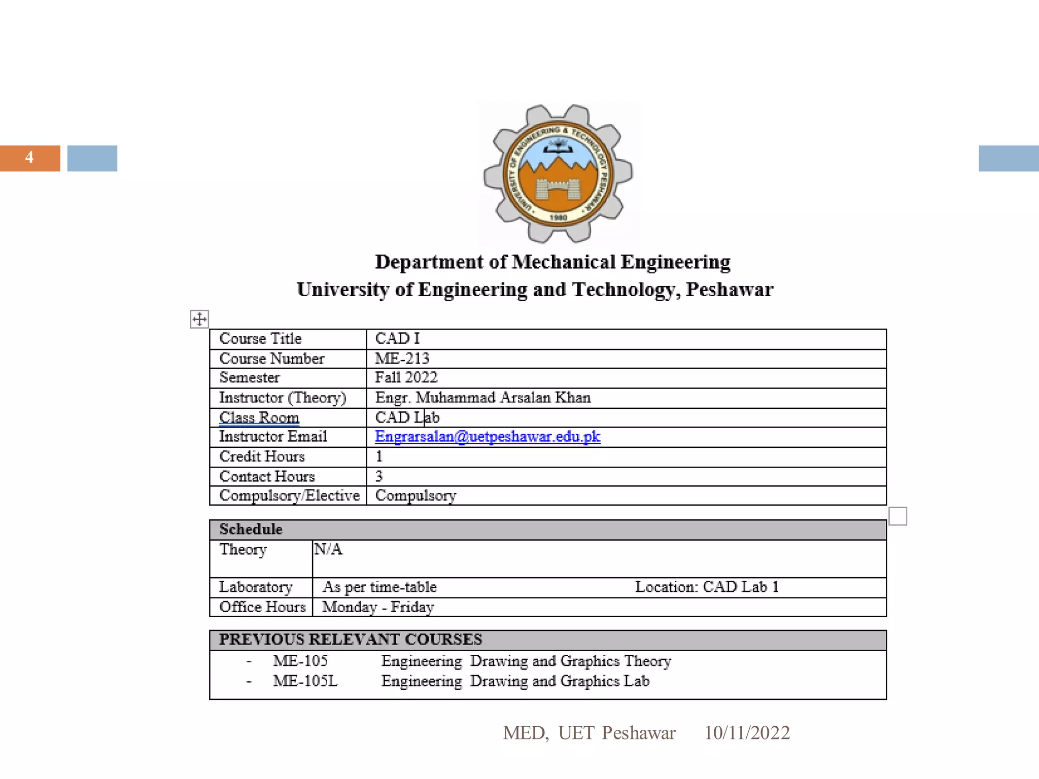
MED, UET Peshawar
10/11/2022
1
Course Name: ME-213 CAD-I Lab
Instructor: Engr. Muhammad Arsalan Khan
Email: engrarsalan@uetpeshawar.edu.pk
10/11/2022
MED, UET Peshawar
2
10/11/2022 3
About Me
Engr. Muhammad Arsalan Khan
• Lecturer, MED UET Peshawar
(Office at MED )
• PhD (I.P) –Mechanical Engineering ( Energy )
(University of Engineering & Technology Peshawar , Pakistan-2019)
• MSc –Mechanical Engineering ( Material Engg. )
(University of Engineering & Technology Peshawar , Pakistan-2018)
• BSc -Mechanical Engineering
(University of Engineering & Technology Peshawar , Pakistan -2013)
engrarsalan@uetpeshawar.edu.pk
10/11/2022
MED, UET Peshawar
4
CAD (Computer aided Designing)
5
 CAD (Computer Aided Design) is the use of computer
software to design and document a product’s design
process.
 Originally CAD includes any technique that use
computers in the design process including drawing,
drafting, and analysis, etc.
 But over the last Four decades, CAD has come to refer
more specifically to Computer Aided Design and
Drafting.
 CAD program/software is an electronic tool that enables
you to make quick and accurate drawings with the use of
a computer.
CAD (Computer aided Designing)
6
 CAD is used to accomplish preliminary design and layouts,
design details and calculations, creating 3-D models, creating
drawings, as well as interfacing with analysis, marketing,
manufacturing.
 CAD is currently widely used for industrial products, animated
movies and other applications. A special printer or plotter is
usually required for printing professional design renderings.
 CAD software enables
1. Efficiency in the quality of design
2. Increase in the Designer’s productivity
3. Improve record keeping through better documentation and
communication
Types of CAD Software
7
Since its introduction in late 1960’s, CAD software has improved by leaps and
bounds. A broad classification of CAD is:
 2D CAD
2D CAD is the pioneer of CAD software,and was developed in the early 70s. At that
time, major automobile, aerospace and other engineering companies developed in-
house tools to automate repetitive drafting requirements. 2D CAD relies on basic
geometric shapes like lines, rectangles, circles, etc. to produceflat drawings. These
types of software havebeen first developed way back in 1970’s. AutoDesk is one of the
pioneering companies that has played a significant role in developing CAD software.
 3D CAD
As the processing power of computersincreased and the graphic display capabilities
improved,3D CAD has becomean increasingly popular design tool. 3D CAD allows
creation of 3D images that are realistic. These images are called 3D models as they can
be viewed and rotated in any direction – X, Y or Z. You can also display views from a 3D
model, such as isometrics or perspectives,fromany angle using 3D CAD.
Types of CAD Software
8
3D CAD can be further classified as:
 Wire-frame models – they create skeleton like models with lines and arcs. Since
they appear to be made of wires, and everythingin the background is visible, they
are called wire-frame models. They are not very popular anymore.
 Surface models – unlike wire frames, these models are created by joining 3D
surfaces. Since nothing in the background is visible, the surface models are quite
realistic.
 Solid models – they are considered to be the most useful CAD models. Although
they appear to be the same as surface models, they also haveadditional properties
like weight, volume and density, just like actual physical objects. These models are
commonly used as prototypesto study engineering designs.
10/11/2022
MED, UET Peshawar
9
Introduction to AutoCAD & History
10
 AutoCAD is a commercial computer-aided design and drafting software
application which is an interactivedrawing system designed to permit a
user to construct or edit a drawing on a graphics display screen.
 It was initially developed in the early 1980's by Autodesk Inc., California.
 It is, by many estimations, the largest program in terms of computer code
ever written for a personal computer.
 AutoCAD is a relativelyeasy program to use after you understand a few
basics.
 AutoCAD providesa set of entities for constructing your drawing. An entity
is a drawing element such as a line, circle, or text string.
 AutoCAD is used across a wide range of industries, by architects, project
managers, engineers,graphic designers, and many other professionals.It
was supported by 750 training centersworldwide in 1994.
 From 1982 to 2022= 37 Versions of AutoCAD has been released world wide.
The AutoCAD Interface
10/11/2022
MED, UET Peshawar
11
 Menu bar Contains the menus
 Toolbars Contain tools, represented by icons, that start commands
 Cursor menu Display a menu at cursor location.
 Crosshairs Controlled by pointing device (a mouse)
 Drawing window Where AutoCAD displays your drawing and where you work on
your drawing
 Command window Where commands are entered from keyboard and AutoCAD
displays prompts and messages.
 Text window Displays a history of the commands and options you have entered.
 Status bar Displays the coordinate location of your crosshairs and the current
setting of grid, snap, and other drawing aids.
Drawing Basics
13
• Up until Release 10, AutoCAD was essentially a two-dimensional
(2D) drawing system.
• Following that release, it now supports a full three-dimensional
(3D) database.
• This has had the effect that the features of AutoCAD that support
two-dimensional drawing are fully self-contained and can still be
used as a 2D systemwithout being concerned with its 3D features.
• From release 11 onwards, AutoCAD has provided an extension
package called AME (Advanced Modeling Extension) which
provides 3D solid modeling capabilities - these allow you to form
complex solid objects by adding, subtracting and intersecting a set
of simple solid primitives (such as, boxes, cone, cylinders, spheres,
etc.).
Drawing Basics
14
 The most important difference between CAD drawings and other
computer graphics is the way the drawing is saved and used.
 Computer images (non CAD images) are bitmaps. Bitmaps are a grid
made up of thousands of dots. Bitmap images lend themselves to
computers because the monitor screens and printers already talk the
language of bitmaps, a map made up of tiny bits.
 The CAD drawing, however, is like a pencil drawing made up of lots of
lines. This is a vector image. Each line in the vector drawing is a
mathematical curve.
 When you click the mouse to start and finish a line, the resulting line
becomes a mathematical formula with a point of beginning, an end
point, a thickness, a color, and a style (dashed, solid, dotted etc).
What's in an AutoCAD drawing
15
• An AutoCAD drawing is made up of entities.
• These can be either simple graphic primitives (such as lines, arcs,
circles, text, and so on) or blocks (which are groups of entities).
• The graphic primitives are defined geometrically in terms of the
normal Cartesian coordinate system (right-handed system with
positive X-axis to the right, positive Y-axis up the screen and
positive Z-axis coming out of the screen towards the user).
• For example, lines are defined by their end point coordinates (x, y
and z), while circles are defined by their centre coordinates and
radius.
• Each entity also has certain attributes associated with it, such as
line style, text font or color.
Entities (Objects)
16
• Every object within an AutoCAD drawing is composed of one or more drawing
entities.
• Entities are the basic parts from which all complex objects within a drawing are
created.
• Each AutoCAD drawing command creates a specific entity type.
• The modifying/editing commands simply manipulate the entities that you have
previously placed in the drawing, scaling them, copying them, or combining
them to create a finished drawing.
• The AutoCAD program works with 17 different entity types.
• All objects in a drawing consist of combinations of one or more of the following
entities:
  Arcs  Points  Lines
  Circles  Blocks  Polylines
  Text  Attributes  3D etc
AutoCAD Commands
17
 Drawing Commands: Creates a specific entity type.
 Point, Line, Circle, Arc, Polyline, Donut, Ellipse, Polygon,
Rectangle, Text etc.
 Modifying Commands: Manipulatesthe entities.
 Select, Erase, Copy, Move, Undo, Rotate, Change, Scale,
Break, Trim, Fillet, Chamfer, Offset etc.
 System Commands:
 New, Open, Save, Save as, Plot, Config, About, Quit, Help,
Shell, List, Status, Area, Cal, etc.
Command Entry
18
• You can entera command in any of the following ways:
◼ 1. Menu bar
◼ 2. Toolbars
◼ 3. Keyboard
• To enter a command from the keyboard, simply type the command
name and press either spacebar, Enter, Tab or the enter key on
mouse.
• The important thing to remember is that AutoCAD will expect you
give it information in a very particularorder.
• The command line tells you what information AutoCAD requires to
continue.
How to download & install AutoCAD 2007
https://www.youtube.com/watch?v=TWDsVtEfBWs
https://www.pirate-bay.net/search?q=autocad+2007?q=autocad+2007#
https://piratebay.party/search/autocad%202007/1/99/0

Lecture 1a.pdf

  • 1.
    MED, UET Peshawar 10/11/2022 1 CourseName: ME-213 CAD-I Lab Instructor: Engr. Muhammad Arsalan Khan Email: engrarsalan@uetpeshawar.edu.pk
  • 2.
  • 3.
    10/11/2022 3 About Me Engr.Muhammad Arsalan Khan • Lecturer, MED UET Peshawar (Office at MED ) • PhD (I.P) –Mechanical Engineering ( Energy ) (University of Engineering & Technology Peshawar , Pakistan-2019) • MSc –Mechanical Engineering ( Material Engg. ) (University of Engineering & Technology Peshawar , Pakistan-2018) • BSc -Mechanical Engineering (University of Engineering & Technology Peshawar , Pakistan -2013) engrarsalan@uetpeshawar.edu.pk
  • 4.
  • 5.
    CAD (Computer aidedDesigning) 5  CAD (Computer Aided Design) is the use of computer software to design and document a product’s design process.  Originally CAD includes any technique that use computers in the design process including drawing, drafting, and analysis, etc.  But over the last Four decades, CAD has come to refer more specifically to Computer Aided Design and Drafting.  CAD program/software is an electronic tool that enables you to make quick and accurate drawings with the use of a computer.
  • 6.
    CAD (Computer aidedDesigning) 6  CAD is used to accomplish preliminary design and layouts, design details and calculations, creating 3-D models, creating drawings, as well as interfacing with analysis, marketing, manufacturing.  CAD is currently widely used for industrial products, animated movies and other applications. A special printer or plotter is usually required for printing professional design renderings.  CAD software enables 1. Efficiency in the quality of design 2. Increase in the Designer’s productivity 3. Improve record keeping through better documentation and communication
  • 7.
    Types of CADSoftware 7 Since its introduction in late 1960’s, CAD software has improved by leaps and bounds. A broad classification of CAD is:  2D CAD 2D CAD is the pioneer of CAD software,and was developed in the early 70s. At that time, major automobile, aerospace and other engineering companies developed in- house tools to automate repetitive drafting requirements. 2D CAD relies on basic geometric shapes like lines, rectangles, circles, etc. to produceflat drawings. These types of software havebeen first developed way back in 1970’s. AutoDesk is one of the pioneering companies that has played a significant role in developing CAD software.  3D CAD As the processing power of computersincreased and the graphic display capabilities improved,3D CAD has becomean increasingly popular design tool. 3D CAD allows creation of 3D images that are realistic. These images are called 3D models as they can be viewed and rotated in any direction – X, Y or Z. You can also display views from a 3D model, such as isometrics or perspectives,fromany angle using 3D CAD.
  • 8.
    Types of CADSoftware 8 3D CAD can be further classified as:  Wire-frame models – they create skeleton like models with lines and arcs. Since they appear to be made of wires, and everythingin the background is visible, they are called wire-frame models. They are not very popular anymore.  Surface models – unlike wire frames, these models are created by joining 3D surfaces. Since nothing in the background is visible, the surface models are quite realistic.  Solid models – they are considered to be the most useful CAD models. Although they appear to be the same as surface models, they also haveadditional properties like weight, volume and density, just like actual physical objects. These models are commonly used as prototypesto study engineering designs.
  • 9.
  • 10.
    Introduction to AutoCAD& History 10  AutoCAD is a commercial computer-aided design and drafting software application which is an interactivedrawing system designed to permit a user to construct or edit a drawing on a graphics display screen.  It was initially developed in the early 1980's by Autodesk Inc., California.  It is, by many estimations, the largest program in terms of computer code ever written for a personal computer.  AutoCAD is a relativelyeasy program to use after you understand a few basics.  AutoCAD providesa set of entities for constructing your drawing. An entity is a drawing element such as a line, circle, or text string.  AutoCAD is used across a wide range of industries, by architects, project managers, engineers,graphic designers, and many other professionals.It was supported by 750 training centersworldwide in 1994.  From 1982 to 2022= 37 Versions of AutoCAD has been released world wide.
  • 11.
    The AutoCAD Interface 10/11/2022 MED,UET Peshawar 11  Menu bar Contains the menus  Toolbars Contain tools, represented by icons, that start commands  Cursor menu Display a menu at cursor location.  Crosshairs Controlled by pointing device (a mouse)  Drawing window Where AutoCAD displays your drawing and where you work on your drawing  Command window Where commands are entered from keyboard and AutoCAD displays prompts and messages.  Text window Displays a history of the commands and options you have entered.  Status bar Displays the coordinate location of your crosshairs and the current setting of grid, snap, and other drawing aids.
  • 13.
    Drawing Basics 13 • Upuntil Release 10, AutoCAD was essentially a two-dimensional (2D) drawing system. • Following that release, it now supports a full three-dimensional (3D) database. • This has had the effect that the features of AutoCAD that support two-dimensional drawing are fully self-contained and can still be used as a 2D systemwithout being concerned with its 3D features. • From release 11 onwards, AutoCAD has provided an extension package called AME (Advanced Modeling Extension) which provides 3D solid modeling capabilities - these allow you to form complex solid objects by adding, subtracting and intersecting a set of simple solid primitives (such as, boxes, cone, cylinders, spheres, etc.).
  • 14.
    Drawing Basics 14  Themost important difference between CAD drawings and other computer graphics is the way the drawing is saved and used.  Computer images (non CAD images) are bitmaps. Bitmaps are a grid made up of thousands of dots. Bitmap images lend themselves to computers because the monitor screens and printers already talk the language of bitmaps, a map made up of tiny bits.  The CAD drawing, however, is like a pencil drawing made up of lots of lines. This is a vector image. Each line in the vector drawing is a mathematical curve.  When you click the mouse to start and finish a line, the resulting line becomes a mathematical formula with a point of beginning, an end point, a thickness, a color, and a style (dashed, solid, dotted etc).
  • 15.
    What's in anAutoCAD drawing 15 • An AutoCAD drawing is made up of entities. • These can be either simple graphic primitives (such as lines, arcs, circles, text, and so on) or blocks (which are groups of entities). • The graphic primitives are defined geometrically in terms of the normal Cartesian coordinate system (right-handed system with positive X-axis to the right, positive Y-axis up the screen and positive Z-axis coming out of the screen towards the user). • For example, lines are defined by their end point coordinates (x, y and z), while circles are defined by their centre coordinates and radius. • Each entity also has certain attributes associated with it, such as line style, text font or color.
  • 16.
    Entities (Objects) 16 • Everyobject within an AutoCAD drawing is composed of one or more drawing entities. • Entities are the basic parts from which all complex objects within a drawing are created. • Each AutoCAD drawing command creates a specific entity type. • The modifying/editing commands simply manipulate the entities that you have previously placed in the drawing, scaling them, copying them, or combining them to create a finished drawing. • The AutoCAD program works with 17 different entity types. • All objects in a drawing consist of combinations of one or more of the following entities:   Arcs  Points  Lines   Circles  Blocks  Polylines   Text  Attributes  3D etc
  • 17.
    AutoCAD Commands 17  DrawingCommands: Creates a specific entity type.  Point, Line, Circle, Arc, Polyline, Donut, Ellipse, Polygon, Rectangle, Text etc.  Modifying Commands: Manipulatesthe entities.  Select, Erase, Copy, Move, Undo, Rotate, Change, Scale, Break, Trim, Fillet, Chamfer, Offset etc.  System Commands:  New, Open, Save, Save as, Plot, Config, About, Quit, Help, Shell, List, Status, Area, Cal, etc.
  • 18.
    Command Entry 18 • Youcan entera command in any of the following ways: ◼ 1. Menu bar ◼ 2. Toolbars ◼ 3. Keyboard • To enter a command from the keyboard, simply type the command name and press either spacebar, Enter, Tab or the enter key on mouse. • The important thing to remember is that AutoCAD will expect you give it information in a very particularorder. • The command line tells you what information AutoCAD requires to continue.
  • 19.
    How to download& install AutoCAD 2007 https://www.youtube.com/watch?v=TWDsVtEfBWs https://www.pirate-bay.net/search?q=autocad+2007?q=autocad+2007# https://piratebay.party/search/autocad%202007/1/99/0