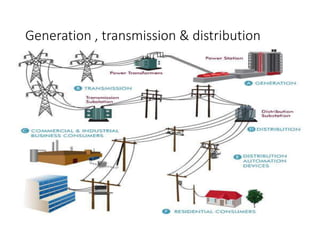
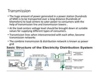
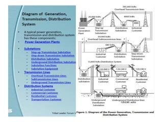
SlideShare a Scribd company logo
Electric power system
Generation, transmission & Distribution
Lecture 1,2
Generation , transmission & distribution
History
• Prior to the discovery of Faraday’s Laws of electromagnetic discussion
Electrical power was available from batteries with limited voltage
and current levels.
 It was not economical to transmit large amount of power over a long
distance.
For a given amount of power, the current magnitude (I = P/V), hence
section of the copper conductor will be large
Thus generation, transmission and distribution of d.c power were
restricted to area of few kilometer radius with no interconnections
between generating plants.
 Therefore, area specific generating stations along with its
distribution networks had to be used.
Changeover from D.C to A.C
• In nineteenth century, it was proposed to have a power system
with 3-phase, 50 Hz A.C generation, transmission and distribution
networks.
• Once AC system was adopted, transmission of large power (MW)
at higher transmission voltage become a reality by using
transformers.
• Nicola Tesla suggested that construction ally simpler electrical
motors (induction motors, without the complexity of commutator
segments of D.C motors) operating from 3-phase AC supply could
be manufactured.
A.C Generator
• Works on Faraday’s law of electromagnetic induction
• A.C power can be generated as a single phase or as a
balanced poly-phase system.
• However, it was found that 3-phase power generation at 50
Hz will be economical and most suitable.
• Present day three phase generators, used to generate 3-
phase power are called alternators (synchronous
generators).
Frequency, voltage & interconnected system
• The frequency of the generated emf for a p polar generator
is given by
f=(P/2)n rps or f=(P/120)n rpm
where n is speed of the generator .
• Frequency of the generated voltage is standardized to 50 Hz
in our country and several European countries.
• In USA and Canada it is 60 Hz.
Frequency, voltage & interconnected system
• The following table gives the rpm at which the generators
with different number of poles are to be driven in order to
generate 50 Hz voltage.
Parallel Generating Stations
• A modern power station has more than one generator and
these generators are connected in parallel.
• Also there exist a large number of power stations spread
over a region or a country.
• A regional power grid is created by interconnecting these
stations through transmission lines.
• In other words, all the generators of different power
stations, in a grid are in effect connected in parallel.
Advantages of Interconnection
• Suppose due to technical problem the generation of a plant becomes nil
or less then, a portion of the demand of power in that area still can be
made from the other power stations connected to the grid.
• One can thus avoid complete shut down of power in an area in case of
technical problem in a particular station.
• It can be shown that in an interconnected system, with more number of
generators connected in parallel, the system voltage and frequency tend
to fixed values irrespective of degree of loading present in the system.
• The Inter connected system however, is to be controlled and monitored
carefully as they may give rise to instability leading to collapse of the
system.
Parallel Generating Stations
• All electrical appliances (fans, refrigerator, TV etc.) to be connected to
A.C supply are therefore designed for a supply frequency of 50 Hz.
• Frequency is one of the parameters which decides the quality of the
supply.
• It is the responsibility of electric supply company to see that frequency is
maintained close to 50 Hz at the consumer premises.
GENERATION
GENERATING STATIONS
• Electric energy is considered superior to all other forms of energy
• Cheaper, economical for all purpose of uses
• Generating station generates electricity
• A generating station essentially employs a prime mover coupled to
an alternator.
• Prime mover converts some form of energy into mechanical energy.
• Alternator converts mechanical energy to electrical energy
GENERATING STATIONS
• Generating stations are classified as mainly,
• Hydro-electric power stations
• Thermal stations
• Nuclear power stations
• Diesel power stations
Sources of energy
• Conventional sources of energy
 hydroelectric
 Thermal
 Nuclear
 Diesel
• Non conventional sources
 Solar
 Wind
 Geothermal
 Tidal
Hydro electricity
• A generating station which utilises the potential energy of water at a high level
for the generation of electrical energy is known as a hydro-electric power
station.
• Hydro electric power is the power from the energy of falling water.
• Most widely used form of renewable energy and is produced in 150 countries.
• The total power that can be generated from hydro electric plant electricity is
Where w=specific wt of water in kg/m^(3),
Q=rate of flow of water in m^(3)/s, H= height of fall in meters, ῃ = overall
efficiency
P = wQhῃ x 9.81 x 10^(-3) kW
Hydro electricity
• Water head is used to drive water turbine coupled to the generator.
• Water head may be available in hilly region naturally in the form of
water reservoir (lakes etc.) at the hill tops.
• The potential energy of water can be used to drive the turbo
generator set installed at the base of the hills through piping called
pen stock.
• Water head may also be created artificially by constructing dams on a
suitable river.
• Water turbines generally operate at low rpm, so number of poles of
the alternator are high.
• For example a 20-pole alternator the rpm of the turbine is only 300
rpm.
Advantage of Hydro-electric power
stations
• No fuel is required by such plants as water is the source of energy.
Hence operating costs are low.
• The plant is highly reliable and it is cheapest in operations and
maintenance.
• It is very neat and clean plant because no smoke or ash is produced
• Such plant are robust and have got longer life.
• Highly skilled engineers are required only at the time of construction
but later on only a few experienced person will be required.
• Such plants in addition to generation of electric power also serve
other purpose such as irrigation and flood control
Disadvantages
• It requires large area
• Its construction cost is very high and takes long time for erection.
• Long transmission lines are required as the plants are located in hilly
areas which are quite away from the load centre.
• There is uncertainty about the availability of huge amount of water
due to dependence of weather conditions.
Thermal stations( steam power plants)
• A thermal power plant is a power plant in which the prime mover is
steam driven
• Water is heated, turns into steam and turns a steam turbine which
drives an electrical generator.
• After it passes through the steam turbine, steam is condensed in a
condenser and recycled to where it was heated; this is known as
Rankin cycle.
• Almost all coal, nuclear, geo thermal ,solar thermal electric etc. are
thermal
Thermal Stations
Schematic diagram of thermal plant
Advantages of steam power plant
• Fuel used is cheaper
• Less space is required in comparison with that of hydroelectric plants
• Cheaper in initial cost in comparison with other types of power
plants of same capacity
• Cheaper in production cost in comparison with that of diesel power
plant
• Such plants can be installed at any place irrespective of the existence
of fuels, while hydro-electric plants can be developed only at the
source of water power
Disadvantages
• High maintenance and operating costs
• Pollution of atmosphere due to fumes and residues from pulverized
fuels
• Requirement of water in large quantity
• Handling of coal and disposal of ash is quite difficult
Nuclear power plants
• Power plants need a source of heat to boil the water which becomes
steam and turbine turns an electrical generator.
• In a nuclear plant the source of heat is a nuclear reactor.
• Fuel for any nuclear reactor is uranium, but not just any uranium.
• Most uranium atoms(99.3% ) consist of a nucleus with 146 uncharged
neutrons and 92 positively charged protons.
• Adding the number of neutrons & protons, these atoms have a total
of 238 neutrons & protons
• However, not all uranium atoms have 146 neutrons; 0.7% have 143 &
this is called as U-235.
• The most important difference is that u-235 spontaneously splits,
producing two smaller nuclei plus 2 to 5 neutrons .
• These neutrons cause further fissions so a chain reaction develops
Nuclear power plants
• To have U-235 fission efficiently, the uranium fuel is enriched.
• Uranium go through a process to increase the content of U-235 from
0.7% to 3 to 4%.
• Process :
Energy is released from uranium
Uranium is atom is split into two
Energy released in the form of radiation & heat.
Uranium is first formed into pallets & then into long rods
The uranium rods are kept cool by submerging them in water.
Moderators are used to reduce the speed of fast neutrons produced
due to nuclear fission process.
Control rods are part of control system of reactor which directly
affects the rate of reaction taking place in the reactor.
Nuclear power plants
• The process is regulated by neutron absorbers in control rods.
• The level of insertion of control rods in the reactor can be adjusted
• The most nuclear fuels are 235U and 239Pu.
Nuclear power generation
Advantages of nuclear power plants
• The amount of fuel required is very small, therefore , there is no
problem of transportation, storage etc.
• These plants require less area as compared to any other type
• These can be located near the load centers, therefore primary
distribution cost is reduced
• These plants are most economical in large capacity
• There are large deposits of nuclear fuels available all over the world.
Therefore such plants can ensure continued supply of electrical
energy for thousands of years
Disadvantages
• The initial capital cost is very high as compared to other types of
power plants
• The erection and commissioning of the plant requires greater
technical knowledge
• The fission by products are generally radio-active and may cause a
dangerous amount of radio active pollution
• Fuel is expensive
• The disposal of products, which are radio-active, is a big problem.
They have either to be disposed off in a deep trench or in a sea away
from sea-shore
POWER GENERATION PLANTS
Power Production In Pakistan
• WAPDA was established in 1958 and having a massive agenda,
which included generation, transmission and distribution of
power along with irrigation, drainage and flood control etc.
• There are four major power producers in country:
1. WAPDA (Water & Power Development Authority),
2. KESCO (Karachi Electric Supply Company),
3. IPPs (Independent Power Producers)
4. PAEC (Pakistan Atomic Energy Commission).
TRANSMISSION
Transmission
• The huge amount of power generated in a power station (hundreds
of MW) is to be transported over a long distance (hundreds of
kilometers) to load centers to cater power to consumers with the
help of transmission line and transmission towers .
• At the load centers voltage level should be brought down at suitable
values for supplying different types of consumers.
• Transmission lines when interconnected with each other, become
transmission networks
• The combine transmission & distribution network is known as power
grid
Consumers
Consumers may be
i. big industries, such as steel plants,
ii. medium and small industries and
iii. offices and domestic consumers.
• Electricity is purchased by different consumers at different voltage
level.
• For example big industries may purchase power at 132 kV, medium
and big industries purchase power at 33 kV or 11 kV and domestic
consumers at rather low voltage of 230V, single phase.
• Thus we see that 400 kV transmission voltage is to be brought down
to different voltage levels before finally delivering power to different
consumers.
• To do this we require obviously step down transformers.
TRANSMISSION
• Electrical energy can be transmitted either by
 Overhead lines or
Underground cables.
• Mostly overhead lines are used for transmission.
• Transmission lines use ACSR (aluminum cable, steel reinforced)
• An ACSR conductor is a stranded cable made of an aluminum alloy
with low resistance and high mechanical strength.
Overhead Transmission lines
• The main advantage of overhead power cables is that they are easy to repair
if damaged.
• They are not restricted by the landscape
• High voltage overhead conductors are not covered by insulation. The
conductor material is nearly always an Aluminium alloy.
• Overhead transmission wires depend on air for insulation
• The design of these lines requires minimum clearances to be observed to
maintain safety.
• An overhead line mainly comprises of the following:
Conductor
Supports or poles
Insulators
Pole fittings
Stays or Guy wire
Lighting arrestors, jumpers, earthing etc.
Underground Transmission lines
• Underground cables take up less right-of-way than overhead lines,
lower visibility , less affected by bad weather.
• However costs of insulated cable and excavation are much higher
then overhead transmission.
• Underground lines are strictly limited by their thermal capacity,
which permits less overload or rerating than overhead lines.
• Long underground AC cables have significant capacitance, which may
reduce their ability to provide useful power to the loads beyond 50
miles.
• Long underground DC cables have no such issue and can run for
thousands of miles
TRANSMISSION LEVELS
• Primary transmission:
• The electric power at 132 kV is transmitted by 3-phase, 3-wire overhead
system to the outskirts of the city. This forms the primary transmission.
• Main voltage levels are 66, 110, 132, 220, 400kV at this stage
• Secondary transmission:
• The primary transmission line terminates at the receiving station (RS)
which usually lies at the outskirts of the city.
• At the receiving station, the voltage is reduced to 33kV by step-down
transformers.
• From this station, electric power is transmitted at 33kV by 3-phase, 3-
wire overhead system to various sub-stations (SS) located at the
strategic points in the city.
• Voltage levels 66, 33kV at this point.
• This forms the secondary transmission.
SUBSTATION (Grid Stations)
• Substation is an intermediate switching, transforming or converting
station between the generating station and the low tension
distribution network situated generally the consumer’s load centre.
• The sub-station receives power from the generating station by a
single or more feeders at a high voltage, transform the same to the
different distribution voltages and sends to different consumers
through distribution network.
Classification of substation
• Substations are classified by two broad categories:-
• According to the service requirement:
• Transformer substation
• Switch substation
• Power factor correction substation
• Frequency change substation
• Converting substation
• Industrial substation
• Collector Substation
• Convertor Substation
• Switching Substation
2. According to the constructional features:
• Indoor substation
• Outdoor substation
• Underground substation
• Pole mounted substation
Substation equipments
• 1. Bus bars
• 2. Insulators
• 3. Isolators
• 4. Circuit breaker
• 5. Power transformer
• 6. Current transformer
• 7. Potential transformer
• 8. Protective relays
• 9. Lightning arresters
• 10.Carrier current equipment
Grid stations in Pakistan
• The three-phase system has three sets of phase conductors.
• LIST OF 500 KV GRID STATIONS
• 1 Grid Station Sheikh Muhammadi Peshawar
• 2 Grid Station Rewat
• 3 Grid Station Sheikhupura
• 4 Grid Station Gatti Faisalabad
• 5 Grid Station Nokhar
• 6 Grid Station New Multan
• 7 Grid Station Muzafargarh
• 8 Grid Station Sahiwal (Yousafwala)
• 9 Grid Station Guddu
• 10 Grid Station Dadu
• 11 Grid Station Jamshoro
• 12 Grid Station Nki
Single line representation of power system
• To represent a practical power system where a lot of
interconnections between several generating stations involving a
large number of transformers using three lines corresponding to R, Y
and B phase will become unnecessary clumsy and complicated.
• To avoid this, a single line along with some symbolical
representations for generator, transformers substation buses are
used to represent a power system rather neatly.
Single line representation
Distribution
Distribution
• Till now we have learnt how power at somewhat high voltage (say 33
kV) is received in a substation situated near load center (a big city).
• The loads of a big city are primarily residential complexes, offices,
schools, hotels, street lighting etc. These types of consumers are
called LT (low tension) consumers.
• Apart from this there may be medium and small scale industries
located in the outskirts of the city.
• LT consumers are to be supplied with single phase, 220 V, 50 Hz.
Distribution
• Step down transformers are used to step down the voltage to 400 V.
• These transformers are called distribution transformers with 400 V, star
connected secondary.
• Such transformers are mounted on poles in cities beside the roads. These
are called pole mounted substations.
• From the secondary of these transformers 4 terminals (R, Y, B and N) come
out.
• N is called the neutral and taken out from the common point of star
connected secondary.
• Voltage between any two phases (i.e., R-Y, Y-B and B-R) is 400 V and
between any phase and neutral is
• 230 V
• Residential buildings are supplied with single phase 230V, 50Hz.
• Primary distribution:
• The secondary transmission line terminates at the sub-station (SS)
where voltage is reduced from 33 kV to 11kV, 3-phase, 3-wire. The 11
kV lines run along the important road sides of the city. This forms the
primary distribution. It may be noted that big consumers (having
demand more than 50 kW) are generally supplied power at 11 kV for
further handling with their own sub-stations.
PRIMARY DISTRIBUTION
• Secondary distribution :
• The electric power from primary distribution line (11 kV) is delivered
to distribution sub-stations (DS).
• These sub-stations are located near the consumers’ localities and
step down the voltage to 400 V, 3-phase, 4-wire for secondary
distribution.
• The voltage between any two phases is 400 V and between any
phase and neutral is 230 V.
SECONDARY DISTRIBUTION
DISTRIBUTORS IN PAKISTAN
• After the transmission , Power is handed over to Distribution
Companies to transfer this power to the consumers of Pakistan.
• 1. PESCO: Peshawar Electric Supply Company, Peshawar, NWFP;
• 2. IESCO: Islamabad Electric Supply Company, Islamabad;
• 3. GEPCO: Gujranwala Electric Power Company, Gujranwala, Punjab;
• 4. LESCO: Lahore Electric Supply Company, Lahore, Punjab;
• 5. FESCO: Faisalabad Electric Supply Company, Faisalabad, Punjab;
• 6. MEPCO: Multan Electric Power Company, Multan, Punjab;
• 7. QESCO: Quetta Electric Supply Company, Quetta, Baluchistan;
• 8. HESCO: Hyderabad Electric Supply Company, Hyderabad, Sindh
IMPORTANT POINTS
• Generation, transmission and distribution of electric power in our
country is carried out as 3-phase system at 50 Hz.
• Three most important conventional methods of power generation in
out country are: coal based thermal plants, Hydel plants and nuclear
plants.
• Load centers (where the power will be actually consumed) are in
general situated far away from the generating station. So to transmit
the large amount of power (hundreds of MW) efficiently and
economically over long distance, high transmission voltage (such as
400 kV, 220 kV) is used.
• Level of current decides the section of the line conductor and the
level of voltage decides the amount of insulation required.

More Related Content

Similar to lecture 1 & 2.pdf electric power system

Hydro power plant
Hydro power plantHydro power plant
Hydro power plant
Naveed Ahmed
 
Small Hydro Power System_Tidal_Ocean Energy.pptx
Small Hydro Power System_Tidal_Ocean Energy.pptxSmall Hydro Power System_Tidal_Ocean Energy.pptx
Small Hydro Power System_Tidal_Ocean Energy.pptx
AmanGanesh1
 
Hdro power plant
Hdro power plantHdro power plant
Hdro power plant
Anshul Kumar Gaur
 
Nuclear
NuclearNuclear
Nuclear
ArjelEscarez
 
Unit-IV.pptx
Unit-IV.pptxUnit-IV.pptx
Unit-IV.pptx
arivazhaganrajangam
 
Unit 5 Energy engg.ppsx
Unit 5 Energy engg.ppsxUnit 5 Energy engg.ppsx
Unit 5 Energy engg.ppsx
MohsinAnsari73
 
Unit-4-POWER FROM RENEWABLE ENERGY.ppt
Unit-4-POWER FROM RENEWABLE ENERGY.pptUnit-4-POWER FROM RENEWABLE ENERGY.ppt
Unit-4-POWER FROM RENEWABLE ENERGY.ppt
dharma raja`
 
Power station or power plant and classification
Power station or power plant and classificationPower station or power plant and classification
Power station or power plant and classificationRajneesh Budania
 
Presentazione_energia_rinnovabile.ppt
Presentazione_energia_rinnovabile.pptPresentazione_energia_rinnovabile.ppt
Presentazione_energia_rinnovabile.ppt
TohidGanjiwale
 
Et wind
Et windEt wind
POWER PLANT.pptx
POWER PLANT.pptxPOWER PLANT.pptx
POWER PLANT.pptx
ssuser140b1b
 
Hydro Energy or Hydro power conversion Technology
Hydro Energy or Hydro power conversion TechnologyHydro Energy or Hydro power conversion Technology
Hydro Energy or Hydro power conversion Technology
Tesfaye Birara
 
Lecture 1 power systems overview
Lecture 1 power systems overviewLecture 1 power systems overview
Lecture 1 power systems overview
syedmunawarabbas
 
BPS-UNIT -I (TPS).pptx
BPS-UNIT -I (TPS).pptxBPS-UNIT -I (TPS).pptx
BPS-UNIT -I (TPS).pptx
aravind649229
 
POWER PLANT ENGINEERING-Unit 4
POWER PLANT ENGINEERING-Unit 4POWER PLANT ENGINEERING-Unit 4
POWER PLANT ENGINEERING-Unit 4
prakash0712
 
Renewable Energy
Renewable EnergyRenewable Energy
Renewable Energy
venkateshR117
 
Unit iv
Unit ivUnit iv
Vocational training at mejia thermal power plant
Vocational training at mejia thermal power plantVocational training at mejia thermal power plant
Vocational training at mejia thermal power plant
Nipak Banerjee
 
TRACTION INVETERS LOCOMOTIVES 10.pptx
TRACTION  INVETERS LOCOMOTIVES 10.pptxTRACTION  INVETERS LOCOMOTIVES 10.pptx
TRACTION INVETERS LOCOMOTIVES 10.pptx
SohailKhan490408
 
Heavy water plant and there electrical systam
Heavy water plant and there electrical systam Heavy water plant and there electrical systam
Heavy water plant and there electrical systam
mohit Navriya
 

Similar to lecture 1 & 2.pdf electric power system (20)

Hydro power plant
Hydro power plantHydro power plant
Hydro power plant
 
Small Hydro Power System_Tidal_Ocean Energy.pptx
Small Hydro Power System_Tidal_Ocean Energy.pptxSmall Hydro Power System_Tidal_Ocean Energy.pptx
Small Hydro Power System_Tidal_Ocean Energy.pptx
 
Hdro power plant
Hdro power plantHdro power plant
Hdro power plant
 
Nuclear
NuclearNuclear
Nuclear
 
Unit-IV.pptx
Unit-IV.pptxUnit-IV.pptx
Unit-IV.pptx
 
Unit 5 Energy engg.ppsx
Unit 5 Energy engg.ppsxUnit 5 Energy engg.ppsx
Unit 5 Energy engg.ppsx
 
Unit-4-POWER FROM RENEWABLE ENERGY.ppt
Unit-4-POWER FROM RENEWABLE ENERGY.pptUnit-4-POWER FROM RENEWABLE ENERGY.ppt
Unit-4-POWER FROM RENEWABLE ENERGY.ppt
 
Power station or power plant and classification
Power station or power plant and classificationPower station or power plant and classification
Power station or power plant and classification
 
Presentazione_energia_rinnovabile.ppt
Presentazione_energia_rinnovabile.pptPresentazione_energia_rinnovabile.ppt
Presentazione_energia_rinnovabile.ppt
 
Et wind
Et windEt wind
Et wind
 
POWER PLANT.pptx
POWER PLANT.pptxPOWER PLANT.pptx
POWER PLANT.pptx
 
Hydro Energy or Hydro power conversion Technology
Hydro Energy or Hydro power conversion TechnologyHydro Energy or Hydro power conversion Technology
Hydro Energy or Hydro power conversion Technology
 
Lecture 1 power systems overview
Lecture 1 power systems overviewLecture 1 power systems overview
Lecture 1 power systems overview
 
BPS-UNIT -I (TPS).pptx
BPS-UNIT -I (TPS).pptxBPS-UNIT -I (TPS).pptx
BPS-UNIT -I (TPS).pptx
 
POWER PLANT ENGINEERING-Unit 4
POWER PLANT ENGINEERING-Unit 4POWER PLANT ENGINEERING-Unit 4
POWER PLANT ENGINEERING-Unit 4
 
Renewable Energy
Renewable EnergyRenewable Energy
Renewable Energy
 
Unit iv
Unit ivUnit iv
Unit iv
 
Vocational training at mejia thermal power plant
Vocational training at mejia thermal power plantVocational training at mejia thermal power plant
Vocational training at mejia thermal power plant
 
TRACTION INVETERS LOCOMOTIVES 10.pptx
TRACTION  INVETERS LOCOMOTIVES 10.pptxTRACTION  INVETERS LOCOMOTIVES 10.pptx
TRACTION INVETERS LOCOMOTIVES 10.pptx
 
Heavy water plant and there electrical systam
Heavy water plant and there electrical systam Heavy water plant and there electrical systam
Heavy water plant and there electrical systam
 

Recently uploaded

一比一原版(UofT毕业证)多伦多大学毕业证成绩单如何办理
一比一原版(UofT毕业证)多伦多大学毕业证成绩单如何办理一比一原版(UofT毕业证)多伦多大学毕业证成绩单如何办理
一比一原版(UofT毕业证)多伦多大学毕业证成绩单如何办理
ydteq
 
Building Electrical System Design & Installation
Building Electrical System Design & InstallationBuilding Electrical System Design & Installation
Building Electrical System Design & Installation
symbo111
 
Nuclear Power Economics and Structuring 2024
Nuclear Power Economics and Structuring 2024Nuclear Power Economics and Structuring 2024
Nuclear Power Economics and Structuring 2024
Massimo Talia
 
Sachpazis:Terzaghi Bearing Capacity Estimation in simple terms with Calculati...
Sachpazis:Terzaghi Bearing Capacity Estimation in simple terms with Calculati...Sachpazis:Terzaghi Bearing Capacity Estimation in simple terms with Calculati...
Sachpazis:Terzaghi Bearing Capacity Estimation in simple terms with Calculati...
Dr.Costas Sachpazis
 
MCQ Soil mechanics questions (Soil shear strength).pdf
MCQ Soil mechanics questions (Soil shear strength).pdfMCQ Soil mechanics questions (Soil shear strength).pdf
MCQ Soil mechanics questions (Soil shear strength).pdf
Osamah Alsalih
 
Water Industry Process Automation and Control Monthly - May 2024.pdf
Water Industry Process Automation and Control Monthly - May 2024.pdfWater Industry Process Automation and Control Monthly - May 2024.pdf
Water Industry Process Automation and Control Monthly - May 2024.pdf
Water Industry Process Automation & Control
 
Industrial Training at Shahjalal Fertilizer Company Limited (SFCL)
Industrial Training at Shahjalal Fertilizer Company Limited (SFCL)Industrial Training at Shahjalal Fertilizer Company Limited (SFCL)
Industrial Training at Shahjalal Fertilizer Company Limited (SFCL)
MdTanvirMahtab2
 
Cosmetic shop management system project report.pdf
Cosmetic shop management system project report.pdfCosmetic shop management system project report.pdf
Cosmetic shop management system project report.pdf
Kamal Acharya
 
Governing Equations for Fundamental Aerodynamics_Anderson2010.pdf
Governing Equations for Fundamental Aerodynamics_Anderson2010.pdfGoverning Equations for Fundamental Aerodynamics_Anderson2010.pdf
Governing Equations for Fundamental Aerodynamics_Anderson2010.pdf
WENKENLI1
 
Unbalanced Three Phase Systems and circuits.pptx
Unbalanced Three Phase Systems and circuits.pptxUnbalanced Three Phase Systems and circuits.pptx
Unbalanced Three Phase Systems and circuits.pptx
ChristineTorrepenida1
 
PPT on GRP pipes manufacturing and testing
PPT on GRP pipes manufacturing and testingPPT on GRP pipes manufacturing and testing
PPT on GRP pipes manufacturing and testing
anoopmanoharan2
 
Planning Of Procurement o different goods and services
Planning Of Procurement o different goods and servicesPlanning Of Procurement o different goods and services
Planning Of Procurement o different goods and services
JoytuBarua2
 
Tutorial for 16S rRNA Gene Analysis with QIIME2.pdf
Tutorial for 16S rRNA Gene Analysis with QIIME2.pdfTutorial for 16S rRNA Gene Analysis with QIIME2.pdf
Tutorial for 16S rRNA Gene Analysis with QIIME2.pdf
aqil azizi
 
NUMERICAL SIMULATIONS OF HEAT AND MASS TRANSFER IN CONDENSING HEAT EXCHANGERS...
NUMERICAL SIMULATIONS OF HEAT AND MASS TRANSFER IN CONDENSING HEAT EXCHANGERS...NUMERICAL SIMULATIONS OF HEAT AND MASS TRANSFER IN CONDENSING HEAT EXCHANGERS...
NUMERICAL SIMULATIONS OF HEAT AND MASS TRANSFER IN CONDENSING HEAT EXCHANGERS...
ssuser7dcef0
 
Steel & Timber Design according to British Standard
Steel & Timber Design according to British StandardSteel & Timber Design according to British Standard
Steel & Timber Design according to British Standard
AkolbilaEmmanuel1
 
Hierarchical Digital Twin of a Naval Power System
Hierarchical Digital Twin of a Naval Power SystemHierarchical Digital Twin of a Naval Power System
Hierarchical Digital Twin of a Naval Power System
Kerry Sado
 
14 Template Contractual Notice - EOT Application
14 Template Contractual Notice - EOT Application14 Template Contractual Notice - EOT Application
14 Template Contractual Notice - EOT Application
SyedAbiiAzazi1
 
Design and Analysis of Algorithms-DP,Backtracking,Graphs,B&B
Design and Analysis of Algorithms-DP,Backtracking,Graphs,B&BDesign and Analysis of Algorithms-DP,Backtracking,Graphs,B&B
Design and Analysis of Algorithms-DP,Backtracking,Graphs,B&B
Sreedhar Chowdam
 
在线办理(ANU毕业证书)澳洲国立大学毕业证录取通知书一模一样
在线办理(ANU毕业证书)澳洲国立大学毕业证录取通知书一模一样在线办理(ANU毕业证书)澳洲国立大学毕业证录取通知书一模一样
在线办理(ANU毕业证书)澳洲国立大学毕业证录取通知书一模一样
obonagu
 
Railway Signalling Principles Edition 3.pdf
Railway Signalling Principles Edition 3.pdfRailway Signalling Principles Edition 3.pdf
Railway Signalling Principles Edition 3.pdf
TeeVichai
 

Recently uploaded (20)

一比一原版(UofT毕业证)多伦多大学毕业证成绩单如何办理
一比一原版(UofT毕业证)多伦多大学毕业证成绩单如何办理一比一原版(UofT毕业证)多伦多大学毕业证成绩单如何办理
一比一原版(UofT毕业证)多伦多大学毕业证成绩单如何办理
 
Building Electrical System Design & Installation
Building Electrical System Design & InstallationBuilding Electrical System Design & Installation
Building Electrical System Design & Installation
 
Nuclear Power Economics and Structuring 2024
Nuclear Power Economics and Structuring 2024Nuclear Power Economics and Structuring 2024
Nuclear Power Economics and Structuring 2024
 
Sachpazis:Terzaghi Bearing Capacity Estimation in simple terms with Calculati...
Sachpazis:Terzaghi Bearing Capacity Estimation in simple terms with Calculati...Sachpazis:Terzaghi Bearing Capacity Estimation in simple terms with Calculati...
Sachpazis:Terzaghi Bearing Capacity Estimation in simple terms with Calculati...
 
MCQ Soil mechanics questions (Soil shear strength).pdf
MCQ Soil mechanics questions (Soil shear strength).pdfMCQ Soil mechanics questions (Soil shear strength).pdf
MCQ Soil mechanics questions (Soil shear strength).pdf
 
Water Industry Process Automation and Control Monthly - May 2024.pdf
Water Industry Process Automation and Control Monthly - May 2024.pdfWater Industry Process Automation and Control Monthly - May 2024.pdf
Water Industry Process Automation and Control Monthly - May 2024.pdf
 
Industrial Training at Shahjalal Fertilizer Company Limited (SFCL)
Industrial Training at Shahjalal Fertilizer Company Limited (SFCL)Industrial Training at Shahjalal Fertilizer Company Limited (SFCL)
Industrial Training at Shahjalal Fertilizer Company Limited (SFCL)
 
Cosmetic shop management system project report.pdf
Cosmetic shop management system project report.pdfCosmetic shop management system project report.pdf
Cosmetic shop management system project report.pdf
 
Governing Equations for Fundamental Aerodynamics_Anderson2010.pdf
Governing Equations for Fundamental Aerodynamics_Anderson2010.pdfGoverning Equations for Fundamental Aerodynamics_Anderson2010.pdf
Governing Equations for Fundamental Aerodynamics_Anderson2010.pdf
 
Unbalanced Three Phase Systems and circuits.pptx
Unbalanced Three Phase Systems and circuits.pptxUnbalanced Three Phase Systems and circuits.pptx
Unbalanced Three Phase Systems and circuits.pptx
 
PPT on GRP pipes manufacturing and testing
PPT on GRP pipes manufacturing and testingPPT on GRP pipes manufacturing and testing
PPT on GRP pipes manufacturing and testing
 
Planning Of Procurement o different goods and services
Planning Of Procurement o different goods and servicesPlanning Of Procurement o different goods and services
Planning Of Procurement o different goods and services
 
Tutorial for 16S rRNA Gene Analysis with QIIME2.pdf
Tutorial for 16S rRNA Gene Analysis with QIIME2.pdfTutorial for 16S rRNA Gene Analysis with QIIME2.pdf
Tutorial for 16S rRNA Gene Analysis with QIIME2.pdf
 
NUMERICAL SIMULATIONS OF HEAT AND MASS TRANSFER IN CONDENSING HEAT EXCHANGERS...
NUMERICAL SIMULATIONS OF HEAT AND MASS TRANSFER IN CONDENSING HEAT EXCHANGERS...NUMERICAL SIMULATIONS OF HEAT AND MASS TRANSFER IN CONDENSING HEAT EXCHANGERS...
NUMERICAL SIMULATIONS OF HEAT AND MASS TRANSFER IN CONDENSING HEAT EXCHANGERS...
 
Steel & Timber Design according to British Standard
Steel & Timber Design according to British StandardSteel & Timber Design according to British Standard
Steel & Timber Design according to British Standard
 
Hierarchical Digital Twin of a Naval Power System
Hierarchical Digital Twin of a Naval Power SystemHierarchical Digital Twin of a Naval Power System
Hierarchical Digital Twin of a Naval Power System
 
14 Template Contractual Notice - EOT Application
14 Template Contractual Notice - EOT Application14 Template Contractual Notice - EOT Application
14 Template Contractual Notice - EOT Application
 
Design and Analysis of Algorithms-DP,Backtracking,Graphs,B&B
Design and Analysis of Algorithms-DP,Backtracking,Graphs,B&BDesign and Analysis of Algorithms-DP,Backtracking,Graphs,B&B
Design and Analysis of Algorithms-DP,Backtracking,Graphs,B&B
 
在线办理(ANU毕业证书)澳洲国立大学毕业证录取通知书一模一样
在线办理(ANU毕业证书)澳洲国立大学毕业证录取通知书一模一样在线办理(ANU毕业证书)澳洲国立大学毕业证录取通知书一模一样
在线办理(ANU毕业证书)澳洲国立大学毕业证录取通知书一模一样
 
Railway Signalling Principles Edition 3.pdf
Railway Signalling Principles Edition 3.pdfRailway Signalling Principles Edition 3.pdf
Railway Signalling Principles Edition 3.pdf
 

lecture 1 & 2.pdf electric power system

  • 1. Electric power system Generation, transmission & Distribution Lecture 1,2
  • 2. Generation , transmission & distribution
  • 3. History • Prior to the discovery of Faraday’s Laws of electromagnetic discussion Electrical power was available from batteries with limited voltage and current levels.  It was not economical to transmit large amount of power over a long distance. For a given amount of power, the current magnitude (I = P/V), hence section of the copper conductor will be large Thus generation, transmission and distribution of d.c power were restricted to area of few kilometer radius with no interconnections between generating plants.  Therefore, area specific generating stations along with its distribution networks had to be used.
  • 4. Changeover from D.C to A.C • In nineteenth century, it was proposed to have a power system with 3-phase, 50 Hz A.C generation, transmission and distribution networks. • Once AC system was adopted, transmission of large power (MW) at higher transmission voltage become a reality by using transformers. • Nicola Tesla suggested that construction ally simpler electrical motors (induction motors, without the complexity of commutator segments of D.C motors) operating from 3-phase AC supply could be manufactured.
  • 5. A.C Generator • Works on Faraday’s law of electromagnetic induction • A.C power can be generated as a single phase or as a balanced poly-phase system. • However, it was found that 3-phase power generation at 50 Hz will be economical and most suitable. • Present day three phase generators, used to generate 3- phase power are called alternators (synchronous generators).
  • 6. Frequency, voltage & interconnected system • The frequency of the generated emf for a p polar generator is given by f=(P/2)n rps or f=(P/120)n rpm where n is speed of the generator . • Frequency of the generated voltage is standardized to 50 Hz in our country and several European countries. • In USA and Canada it is 60 Hz.
  • 7. Frequency, voltage & interconnected system • The following table gives the rpm at which the generators with different number of poles are to be driven in order to generate 50 Hz voltage.
  • 8. Parallel Generating Stations • A modern power station has more than one generator and these generators are connected in parallel. • Also there exist a large number of power stations spread over a region or a country. • A regional power grid is created by interconnecting these stations through transmission lines. • In other words, all the generators of different power stations, in a grid are in effect connected in parallel.
  • 9. Advantages of Interconnection • Suppose due to technical problem the generation of a plant becomes nil or less then, a portion of the demand of power in that area still can be made from the other power stations connected to the grid. • One can thus avoid complete shut down of power in an area in case of technical problem in a particular station. • It can be shown that in an interconnected system, with more number of generators connected in parallel, the system voltage and frequency tend to fixed values irrespective of degree of loading present in the system. • The Inter connected system however, is to be controlled and monitored carefully as they may give rise to instability leading to collapse of the system.
  • 10. Parallel Generating Stations • All electrical appliances (fans, refrigerator, TV etc.) to be connected to A.C supply are therefore designed for a supply frequency of 50 Hz. • Frequency is one of the parameters which decides the quality of the supply. • It is the responsibility of electric supply company to see that frequency is maintained close to 50 Hz at the consumer premises.
  • 12. GENERATING STATIONS • Electric energy is considered superior to all other forms of energy • Cheaper, economical for all purpose of uses • Generating station generates electricity • A generating station essentially employs a prime mover coupled to an alternator. • Prime mover converts some form of energy into mechanical energy. • Alternator converts mechanical energy to electrical energy
  • 13. GENERATING STATIONS • Generating stations are classified as mainly, • Hydro-electric power stations • Thermal stations • Nuclear power stations • Diesel power stations
  • 14. Sources of energy • Conventional sources of energy  hydroelectric  Thermal  Nuclear  Diesel • Non conventional sources  Solar  Wind  Geothermal  Tidal
  • 15. Hydro electricity • A generating station which utilises the potential energy of water at a high level for the generation of electrical energy is known as a hydro-electric power station. • Hydro electric power is the power from the energy of falling water. • Most widely used form of renewable energy and is produced in 150 countries. • The total power that can be generated from hydro electric plant electricity is Where w=specific wt of water in kg/m^(3), Q=rate of flow of water in m^(3)/s, H= height of fall in meters, ῃ = overall efficiency P = wQhῃ x 9.81 x 10^(-3) kW
  • 16.
  • 17. Hydro electricity • Water head is used to drive water turbine coupled to the generator. • Water head may be available in hilly region naturally in the form of water reservoir (lakes etc.) at the hill tops. • The potential energy of water can be used to drive the turbo generator set installed at the base of the hills through piping called pen stock. • Water head may also be created artificially by constructing dams on a suitable river. • Water turbines generally operate at low rpm, so number of poles of the alternator are high. • For example a 20-pole alternator the rpm of the turbine is only 300 rpm.
  • 18. Advantage of Hydro-electric power stations • No fuel is required by such plants as water is the source of energy. Hence operating costs are low. • The plant is highly reliable and it is cheapest in operations and maintenance. • It is very neat and clean plant because no smoke or ash is produced • Such plant are robust and have got longer life. • Highly skilled engineers are required only at the time of construction but later on only a few experienced person will be required. • Such plants in addition to generation of electric power also serve other purpose such as irrigation and flood control
  • 19. Disadvantages • It requires large area • Its construction cost is very high and takes long time for erection. • Long transmission lines are required as the plants are located in hilly areas which are quite away from the load centre. • There is uncertainty about the availability of huge amount of water due to dependence of weather conditions.
  • 20. Thermal stations( steam power plants) • A thermal power plant is a power plant in which the prime mover is steam driven • Water is heated, turns into steam and turns a steam turbine which drives an electrical generator. • After it passes through the steam turbine, steam is condensed in a condenser and recycled to where it was heated; this is known as Rankin cycle. • Almost all coal, nuclear, geo thermal ,solar thermal electric etc. are thermal
  • 22. Schematic diagram of thermal plant
  • 23. Advantages of steam power plant • Fuel used is cheaper • Less space is required in comparison with that of hydroelectric plants • Cheaper in initial cost in comparison with other types of power plants of same capacity • Cheaper in production cost in comparison with that of diesel power plant • Such plants can be installed at any place irrespective of the existence of fuels, while hydro-electric plants can be developed only at the source of water power
  • 24. Disadvantages • High maintenance and operating costs • Pollution of atmosphere due to fumes and residues from pulverized fuels • Requirement of water in large quantity • Handling of coal and disposal of ash is quite difficult
  • 25. Nuclear power plants • Power plants need a source of heat to boil the water which becomes steam and turbine turns an electrical generator. • In a nuclear plant the source of heat is a nuclear reactor. • Fuel for any nuclear reactor is uranium, but not just any uranium. • Most uranium atoms(99.3% ) consist of a nucleus with 146 uncharged neutrons and 92 positively charged protons. • Adding the number of neutrons & protons, these atoms have a total of 238 neutrons & protons • However, not all uranium atoms have 146 neutrons; 0.7% have 143 & this is called as U-235. • The most important difference is that u-235 spontaneously splits, producing two smaller nuclei plus 2 to 5 neutrons . • These neutrons cause further fissions so a chain reaction develops
  • 26. Nuclear power plants • To have U-235 fission efficiently, the uranium fuel is enriched. • Uranium go through a process to increase the content of U-235 from 0.7% to 3 to 4%. • Process : Energy is released from uranium Uranium is atom is split into two Energy released in the form of radiation & heat. Uranium is first formed into pallets & then into long rods The uranium rods are kept cool by submerging them in water. Moderators are used to reduce the speed of fast neutrons produced due to nuclear fission process. Control rods are part of control system of reactor which directly affects the rate of reaction taking place in the reactor.
  • 27. Nuclear power plants • The process is regulated by neutron absorbers in control rods. • The level of insertion of control rods in the reactor can be adjusted • The most nuclear fuels are 235U and 239Pu.
  • 29. Advantages of nuclear power plants • The amount of fuel required is very small, therefore , there is no problem of transportation, storage etc. • These plants require less area as compared to any other type • These can be located near the load centers, therefore primary distribution cost is reduced • These plants are most economical in large capacity • There are large deposits of nuclear fuels available all over the world. Therefore such plants can ensure continued supply of electrical energy for thousands of years
  • 30. Disadvantages • The initial capital cost is very high as compared to other types of power plants • The erection and commissioning of the plant requires greater technical knowledge • The fission by products are generally radio-active and may cause a dangerous amount of radio active pollution • Fuel is expensive • The disposal of products, which are radio-active, is a big problem. They have either to be disposed off in a deep trench or in a sea away from sea-shore
  • 32. Power Production In Pakistan • WAPDA was established in 1958 and having a massive agenda, which included generation, transmission and distribution of power along with irrigation, drainage and flood control etc. • There are four major power producers in country: 1. WAPDA (Water & Power Development Authority), 2. KESCO (Karachi Electric Supply Company), 3. IPPs (Independent Power Producers) 4. PAEC (Pakistan Atomic Energy Commission).
  • 33.
  • 35. Transmission • The huge amount of power generated in a power station (hundreds of MW) is to be transported over a long distance (hundreds of kilometers) to load centers to cater power to consumers with the help of transmission line and transmission towers . • At the load centers voltage level should be brought down at suitable values for supplying different types of consumers. • Transmission lines when interconnected with each other, become transmission networks • The combine transmission & distribution network is known as power grid
  • 36. Consumers Consumers may be i. big industries, such as steel plants, ii. medium and small industries and iii. offices and domestic consumers. • Electricity is purchased by different consumers at different voltage level. • For example big industries may purchase power at 132 kV, medium and big industries purchase power at 33 kV or 11 kV and domestic consumers at rather low voltage of 230V, single phase. • Thus we see that 400 kV transmission voltage is to be brought down to different voltage levels before finally delivering power to different consumers. • To do this we require obviously step down transformers.
  • 37.
  • 38. TRANSMISSION • Electrical energy can be transmitted either by  Overhead lines or Underground cables. • Mostly overhead lines are used for transmission. • Transmission lines use ACSR (aluminum cable, steel reinforced) • An ACSR conductor is a stranded cable made of an aluminum alloy with low resistance and high mechanical strength.
  • 39. Overhead Transmission lines • The main advantage of overhead power cables is that they are easy to repair if damaged. • They are not restricted by the landscape • High voltage overhead conductors are not covered by insulation. The conductor material is nearly always an Aluminium alloy. • Overhead transmission wires depend on air for insulation • The design of these lines requires minimum clearances to be observed to maintain safety. • An overhead line mainly comprises of the following: Conductor Supports or poles Insulators Pole fittings Stays or Guy wire Lighting arrestors, jumpers, earthing etc.
  • 40.
  • 41. Underground Transmission lines • Underground cables take up less right-of-way than overhead lines, lower visibility , less affected by bad weather. • However costs of insulated cable and excavation are much higher then overhead transmission. • Underground lines are strictly limited by their thermal capacity, which permits less overload or rerating than overhead lines. • Long underground AC cables have significant capacitance, which may reduce their ability to provide useful power to the loads beyond 50 miles. • Long underground DC cables have no such issue and can run for thousands of miles
  • 42.
  • 43. TRANSMISSION LEVELS • Primary transmission: • The electric power at 132 kV is transmitted by 3-phase, 3-wire overhead system to the outskirts of the city. This forms the primary transmission. • Main voltage levels are 66, 110, 132, 220, 400kV at this stage • Secondary transmission: • The primary transmission line terminates at the receiving station (RS) which usually lies at the outskirts of the city. • At the receiving station, the voltage is reduced to 33kV by step-down transformers. • From this station, electric power is transmitted at 33kV by 3-phase, 3- wire overhead system to various sub-stations (SS) located at the strategic points in the city. • Voltage levels 66, 33kV at this point. • This forms the secondary transmission.
  • 44.
  • 45. SUBSTATION (Grid Stations) • Substation is an intermediate switching, transforming or converting station between the generating station and the low tension distribution network situated generally the consumer’s load centre. • The sub-station receives power from the generating station by a single or more feeders at a high voltage, transform the same to the different distribution voltages and sends to different consumers through distribution network.
  • 46. Classification of substation • Substations are classified by two broad categories:- • According to the service requirement: • Transformer substation • Switch substation • Power factor correction substation • Frequency change substation • Converting substation • Industrial substation • Collector Substation • Convertor Substation • Switching Substation 2. According to the constructional features: • Indoor substation • Outdoor substation • Underground substation • Pole mounted substation
  • 47. Substation equipments • 1. Bus bars • 2. Insulators • 3. Isolators • 4. Circuit breaker • 5. Power transformer • 6. Current transformer • 7. Potential transformer • 8. Protective relays • 9. Lightning arresters • 10.Carrier current equipment
  • 48.
  • 49.
  • 50.
  • 51.
  • 52. Grid stations in Pakistan • The three-phase system has three sets of phase conductors. • LIST OF 500 KV GRID STATIONS • 1 Grid Station Sheikh Muhammadi Peshawar • 2 Grid Station Rewat • 3 Grid Station Sheikhupura • 4 Grid Station Gatti Faisalabad • 5 Grid Station Nokhar • 6 Grid Station New Multan • 7 Grid Station Muzafargarh • 8 Grid Station Sahiwal (Yousafwala) • 9 Grid Station Guddu • 10 Grid Station Dadu • 11 Grid Station Jamshoro • 12 Grid Station Nki
  • 53. Single line representation of power system • To represent a practical power system where a lot of interconnections between several generating stations involving a large number of transformers using three lines corresponding to R, Y and B phase will become unnecessary clumsy and complicated. • To avoid this, a single line along with some symbolical representations for generator, transformers substation buses are used to represent a power system rather neatly.
  • 57. Distribution • Till now we have learnt how power at somewhat high voltage (say 33 kV) is received in a substation situated near load center (a big city). • The loads of a big city are primarily residential complexes, offices, schools, hotels, street lighting etc. These types of consumers are called LT (low tension) consumers. • Apart from this there may be medium and small scale industries located in the outskirts of the city. • LT consumers are to be supplied with single phase, 220 V, 50 Hz.
  • 58. Distribution • Step down transformers are used to step down the voltage to 400 V. • These transformers are called distribution transformers with 400 V, star connected secondary. • Such transformers are mounted on poles in cities beside the roads. These are called pole mounted substations. • From the secondary of these transformers 4 terminals (R, Y, B and N) come out. • N is called the neutral and taken out from the common point of star connected secondary. • Voltage between any two phases (i.e., R-Y, Y-B and B-R) is 400 V and between any phase and neutral is • 230 V • Residential buildings are supplied with single phase 230V, 50Hz.
  • 59. • Primary distribution: • The secondary transmission line terminates at the sub-station (SS) where voltage is reduced from 33 kV to 11kV, 3-phase, 3-wire. The 11 kV lines run along the important road sides of the city. This forms the primary distribution. It may be noted that big consumers (having demand more than 50 kW) are generally supplied power at 11 kV for further handling with their own sub-stations.
  • 61. • Secondary distribution : • The electric power from primary distribution line (11 kV) is delivered to distribution sub-stations (DS). • These sub-stations are located near the consumers’ localities and step down the voltage to 400 V, 3-phase, 4-wire for secondary distribution. • The voltage between any two phases is 400 V and between any phase and neutral is 230 V.
  • 63. DISTRIBUTORS IN PAKISTAN • After the transmission , Power is handed over to Distribution Companies to transfer this power to the consumers of Pakistan. • 1. PESCO: Peshawar Electric Supply Company, Peshawar, NWFP; • 2. IESCO: Islamabad Electric Supply Company, Islamabad; • 3. GEPCO: Gujranwala Electric Power Company, Gujranwala, Punjab; • 4. LESCO: Lahore Electric Supply Company, Lahore, Punjab; • 5. FESCO: Faisalabad Electric Supply Company, Faisalabad, Punjab; • 6. MEPCO: Multan Electric Power Company, Multan, Punjab; • 7. QESCO: Quetta Electric Supply Company, Quetta, Baluchistan; • 8. HESCO: Hyderabad Electric Supply Company, Hyderabad, Sindh
  • 64. IMPORTANT POINTS • Generation, transmission and distribution of electric power in our country is carried out as 3-phase system at 50 Hz. • Three most important conventional methods of power generation in out country are: coal based thermal plants, Hydel plants and nuclear plants. • Load centers (where the power will be actually consumed) are in general situated far away from the generating station. So to transmit the large amount of power (hundreds of MW) efficiently and economically over long distance, high transmission voltage (such as 400 kV, 220 kV) is used. • Level of current decides the section of the line conductor and the level of voltage decides the amount of insulation required.