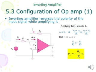
1
Alexander-Sadiku
Fundamentals of Electric
Circuits
Chapter 5
Operational Amplifier
Copyright © The McGraw-Hill Companies, Inc. Permission required for reproduction or display.
2
Operational Amplifier - Chapter 5
5.1 What is an Op Amp?
5.2 Ideal Op Amp
5.3 Configuration of Op Amp
5.4 Cascaded Op Amp
5.5 Application
– Digital-to Analog Converter
3
5.1 What is an Op Amp (1)
• It is an electronic unit that behaves
like a voltage-controlled voltage
source.
• It is an active circuit element
designed to perform mathematical
operations of addition, subtraction,
multiplication, division,
differentiation and integration.
4
5.1 What is an Op Amp (2)
A typical op amp 741: (a) pin configuration, (b) circuit symbol
5
5.1 What is an Op Amp (3)
The equivalent circuit
Of the non-ideal op amp
Op Amp output:
vo as a function of Vd
vd = v2 – v1; vo = Avd = A(v2 –v1)
6
7
Parameter Typical range Ideal values
Open-loop gain, A 105 to 108  ∞
Input resistance, Ri 105 to 1013  ∞ 
Output resistance, Ro 10 to 100  0 
Supply voltage, VCC 5 to 24 V
5.1 What is an Op Amp (4)
Typical ranges for op amp parameters
8
5.2 Ideal Op Amp (1)
An ideal op amp has the following characteristics:
1. Infinite open-loop gain, A ≈ ∞
2. Infinite input resistance, Ri ≈ ∞
3. Zero output resistance, Ro ≈ 0
9
10
11
12
5.3 Configuration of Op amp (1)
• Inverting amplifier reverses the polarity of the
input signal while amplifying it
i
f
o v
R
R
v
1


13
5.3 Configuration of Op amp (2)
Example 2
Refer to the op amp below. If vi = 0.5V, calculate:
(a) the output voltage, vo and (b) the current in
the 10k resistor.
14
15
5.3 Configuration of Op amp (3)
• Non-inverting amplifier is designed to produce
positive voltage gain
i
f
o v
R
R
v 









1
1
16
17
18
5.3 Configuration of Op amp (5)
• Summing Amplifier is an op amp circuit that
combines several inputs and produces an output
that is the weighted sum of the inputs.











 3
3
2
2
1
1
v
R
R
v
R
R
v
R
R
v
f
f
f
o
19
5.3 Configuration of Op amp (6)
Example 4
Calculate vo and io in the op amp circuit shown
below.
20
5.3 Configuration of Op amp (7)
• Difference amplifier is a device that amplifies the
difference between two inputs but rejects any
signals common to the two inputs.
1
if
,
)
/
1
(
)
/
1
(
4
3
2
1
1
2
1
1
2
2
4
3
1
2
1
2









R
R
R
R
v
v
v
v
R
R
v
R
R
R
R
R
R
v o
o
21
22
23
Integrator
The output is the
integral of the input;
i.e., proportional to the
area under the input
waveform. This circuit
is useful in low-pass
filter circuits and sensor
conditioning circuits.


 dt
t
v
RC
t
vo )
(
1
)
( 1
Differentiator
The differentiator
takes the derivative
of the input. This
circuit is useful in
high-pass filter
circuits.
dt
t
dv
RC
t
vo
)
(
)
( 1


28
5.4 Cascaded Op Amp (1)
• It is a head-to-tail arrangement of two or more
op amp circuits such that the output to one is the
input of the next.
29
5.4 Cascaded Op Amp (2)
Example 6
Find vo and io in the circuit shown below.
30
31
5.5 Application (1)
• Digital-to Analog Converter (DAC) : it is a device
which transforms digital signals into analog form.
4
4
3
3
2
2
1
1
0 V
R
R
V
R
R
V
R
R
V
R
R
V
f
f
f
f





Four-bit DCA: (a) block diagram (b) binary weighted ladder type
where
V1 – MSB, V4 – LSB
V1 to V4 are either 0 or 1 V
32
33
34
35
36
37

Lecture 1

  • 1.
    1 Alexander-Sadiku Fundamentals of Electric Circuits Chapter5 Operational Amplifier Copyright © The McGraw-Hill Companies, Inc. Permission required for reproduction or display.
  • 2.
    2 Operational Amplifier -Chapter 5 5.1 What is an Op Amp? 5.2 Ideal Op Amp 5.3 Configuration of Op Amp 5.4 Cascaded Op Amp 5.5 Application – Digital-to Analog Converter
  • 3.
    3 5.1 What isan Op Amp (1) • It is an electronic unit that behaves like a voltage-controlled voltage source. • It is an active circuit element designed to perform mathematical operations of addition, subtraction, multiplication, division, differentiation and integration.
  • 4.
    4 5.1 What isan Op Amp (2) A typical op amp 741: (a) pin configuration, (b) circuit symbol
  • 5.
    5 5.1 What isan Op Amp (3) The equivalent circuit Of the non-ideal op amp Op Amp output: vo as a function of Vd vd = v2 – v1; vo = Avd = A(v2 –v1)
  • 6.
  • 7.
    7 Parameter Typical rangeIdeal values Open-loop gain, A 105 to 108  ∞ Input resistance, Ri 105 to 1013  ∞  Output resistance, Ro 10 to 100  0  Supply voltage, VCC 5 to 24 V 5.1 What is an Op Amp (4) Typical ranges for op amp parameters
  • 8.
    8 5.2 Ideal OpAmp (1) An ideal op amp has the following characteristics: 1. Infinite open-loop gain, A ≈ ∞ 2. Infinite input resistance, Ri ≈ ∞ 3. Zero output resistance, Ro ≈ 0
  • 9.
  • 10.
  • 11.
  • 12.
    12 5.3 Configuration ofOp amp (1) • Inverting amplifier reverses the polarity of the input signal while amplifying it i f o v R R v 1  
  • 13.
    13 5.3 Configuration ofOp amp (2) Example 2 Refer to the op amp below. If vi = 0.5V, calculate: (a) the output voltage, vo and (b) the current in the 10k resistor.
  • 14.
  • 15.
    15 5.3 Configuration ofOp amp (3) • Non-inverting amplifier is designed to produce positive voltage gain i f o v R R v           1 1
  • 16.
  • 17.
  • 18.
    18 5.3 Configuration ofOp amp (5) • Summing Amplifier is an op amp circuit that combines several inputs and produces an output that is the weighted sum of the inputs.             3 3 2 2 1 1 v R R v R R v R R v f f f o
  • 19.
    19 5.3 Configuration ofOp amp (6) Example 4 Calculate vo and io in the op amp circuit shown below.
  • 20.
    20 5.3 Configuration ofOp amp (7) • Difference amplifier is a device that amplifies the difference between two inputs but rejects any signals common to the two inputs. 1 if , ) / 1 ( ) / 1 ( 4 3 2 1 1 2 1 1 2 2 4 3 1 2 1 2          R R R R v v v v R R v R R R R R R v o o
  • 21.
  • 22.
  • 23.
  • 24.
    Integrator The output isthe integral of the input; i.e., proportional to the area under the input waveform. This circuit is useful in low-pass filter circuits and sensor conditioning circuits.    dt t v RC t vo ) ( 1 ) ( 1
  • 27.
    Differentiator The differentiator takes thederivative of the input. This circuit is useful in high-pass filter circuits. dt t dv RC t vo ) ( ) ( 1  
  • 28.
    28 5.4 Cascaded OpAmp (1) • It is a head-to-tail arrangement of two or more op amp circuits such that the output to one is the input of the next.
  • 29.
    29 5.4 Cascaded OpAmp (2) Example 6 Find vo and io in the circuit shown below.
  • 30.
  • 31.
    31 5.5 Application (1) •Digital-to Analog Converter (DAC) : it is a device which transforms digital signals into analog form. 4 4 3 3 2 2 1 1 0 V R R V R R V R R V R R V f f f f      Four-bit DCA: (a) block diagram (b) binary weighted ladder type where V1 – MSB, V4 – LSB V1 to V4 are either 0 or 1 V
  • 32.
  • 33.
  • 34.
  • 35.
  • 36.
  • 37.