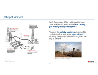
LOPA
Layer of Protection Analysis
Er. Srinivasan Premkumar
Director & Chief Process Safety Specialist
ALARP Process Safety Solutions
Layer of Protection Analysis (LOPA) – Introduction
LOPA
Disclaimer
• Though every effort has been taken to assure the accuracy and reliability of the content, no part of
the content shall constitute a standard, or an endorsement, recommendation or definitive
guidance. The content is offered as a guide for the knowledge and awareness on the
fundamentals and first principles. Nothing in the content shall be directly applied without an
independent professional advice. Neither the author nor the organization under which the author
is employed takes responsibility for any errors or omissions.
2
LOPA
Bhopal Incident
3
Source: Bhopal.org
On 3 December 1984, a Union Carbide
plant in Bhopal, India leaked the deadly
gas methyl isocyanate (MIC)
None of the safety systems designed to
contain such a leak were operational,
allowing the gas to spread throughout the
city of Bhopal
LOPA
Normal Operation
4
Atmospheric Vent
MIC Inlet
MIC Outlet
MIC Storage Tank
Refrigeration
System
Relief Vent Header
Scrubber Knockout Drum Flare Stack
Process Vent Header
NC (or Blinded)
NaOH
NaOH for Treatment
- 3 MIC storage tanks
- 2 for storage and 1 on standby
- Max operating level is 50%
LOPA
Original Design Considerations
5
Atmospheric Vent
MIC Inlet
MIC Outlet
MIC Storage Tank
Refrigeration
System
Relief Vent Header
Scrubber Knockout Drum Flare Stack
Process Vent Header
NC (or Blinded)
NaOH
NaOH for Treatment
Layer 1
(Process
Design &
Operating
Philosophy)
Layer 2
(BPCS –
Temperature
Control)
Layer 3
(Critical
Alarms &
Response)
Layer 4
(Automation
– SIS or ESD)
– None
Layer 5
(Relief
System)
Layer 6
(Flare)
Layer 7
(Emergency
Response)
LOPA
What happened?
6
Atmospheric Vent
MIC Inlet
MIC Outlet
MIC Storage Tank
Refrigeration
System
Relief Vent Header
Scrubber Knockout Drum Flare Stack
Process Vent Header
NaOH
NaOH for Treatment
LOPA
What happened?
7
Atmospheric Vent
MIC Inlet
MIC Outlet
MIC Storage Tank
Refrigeration
System
Relief Vent Header
Scrubber Knockout Drum Flare Stack
Process Vent Header
NaOH
NaOH for Treatment
Layer 1
(Process
Design &
Operating
Philosophy)
Layer 2
(BPCS –
Temperature
Control)
Layer 3
(Critical
Alarms &
Response)
Layer 4
(Automation
– SIS or ESD)
– None
Layer 5
(Relief
System)
Layer 6
(Flare)
Layer 7
(Emergency
Response)
LOPA
Layers of Protection – Process Related Hazards
8
Emergency Response
Physical Protection (post-release)
e.g. dike
Physical Protection (pre-release)
e.g. pressure relief valve
Automatic Shutdown System
e.g. SIF, ESD
Critical Alarms & Operator
Response
Basic Process Control
System
Process Design
LOPA
What is LOPA?
• LOPA is a semi-quantitative risk assessment tool for analyzing and assessing the risks of the
scenarios with higher consequence of concern (e.g. major accident scenarios)
– The risk is compared against the company’s risk tolerance criteria
– If the risk is at an unacceptable level, additional protection layers (i.e. control measures) are identified and
suggested for implementation
• Risk is a function of likelihood and severity (i.e. consequence)
• The LOPA uses order-of-magnitude estimates for determining the likelihood
• The severity is typically assessed qualitatively in reference to the company Risk Matrix definitions
– Alternatively, mathematical consequence analysis results can be used to assess the severity (if required)
• LOPA is one of the commonly applied tools for determining the required Safety Integrity Level
(SIL) in a Safety Instrumented Function (SIF)
9
LOPA
Scenario-Based Risk Assessment Tool
• LOPA is applied to the scenario-based risk assessments
• LOPA is applied to a single initiating event and a single consequence pair
• The scenario starts with an initiating event, propagates through the cascading events and other
unfavorable conditions and results in a consequence of concern
– Initiating event refers to the cause that triggers/initiates the scenario
– Cascading events refer to the coincident failures of other protection layers
– Other unfavorable conditions refer to factors/conditions that must be present for the consequence to occur
10
LOPA
Example
11
To Atmosphere
to a Safe Location
Propane From Upstream Unit
Maximum possible source pressure is 25barg
Normal operating pressure is 12barg
Set Pressure: 18barg
MAWP (Design Pressure): 20barg
LI-2
SIS
Maximum Operating
Level
Propane
To Downstream Unit
LI-1
LAH
LIC-1
LOPA
Example - Background
• Let us assume it is an intermediate pressure storage tank that continuously takes propane from
the upstream unit and feeds to the downstream unit
• From the schematic, it can be seen there is a potential for a liquid overfill to occur should there be
an equipment, instrumentation and/or human failure
• In case of a loss of containment of propane to atmosphere through the pressure relief device
(PRD), there is a potential for a vapor cloud explosion (VCE), flash fire, jet fire
– Pool fire may be credible depending upon the flash fraction
– For the discussion sake, let us assume that propane doesn’t contain any toxics
• Several causes could trigger the liquid overfill scenario
– Bottom pump failure in the pressure storage tank
– LI-1 fails to function
– The upstream unit sends flowrate in excess of the maximum normal flowrate
12
LOPA
Example LOPA Scenarios
• Scenario 1: During the normal operation, pressure storage bottom pump fails due to a power
loss, operator is unable to respond in time to the level high alarm from LI-1, liquid overfill occurs,
LI-2 and the associated Safety Instrumented Function (SIF) fails to work on high high liquid level,
the pressure storage vessel overpressures and liquid overflows through the PRD, propane
releases, ignites and results in a flash fire. There is a potential for personnel within the flash fire
zone to be fatally injured.
• Scenario 2: During the normal operation, pressure storage bottom pump fails due to a power
loss, operator is unable to respond in time to the level high alarm from LI-1, liquid overfill occurs,
LI-2 and the associated Safety Instrumented Function (SIF) fails to work on high high liquid level,
the pressure storage vessel overpressures and liquid overflows through the PRD, propane
releases, ignites and results in a VCE. There is a potential for personnel within the overpressure
impact zone (including personnel in the occupied buildings) to be fatally/seriously injured.
13
LOPA
LOPA Terminologies
• Initiating Event (IE) is a failure that starts the sequence of events that, if not interrupted by the
successful operation of a protection layer (i.e. control measure) results in a hazardous outcome
– The initiating events can be due to equipment failure, instrumentation failure, human failure and external events
– The Initiating Event Frequency (IEF) refers to the frequency of occurrence of the initiating event
• Independent Protection Layers (IPLs) are control measures that can prevent the initiating event
from propagating to a hazardous outcome without being adversely affected by either the initiating
event or by the action (or inaction) of any other IPLs
– Every IPL must be independent from the initiating event and other IPLs in the same scenario
– The IPLs must be effective to address the consequence of concern
– The IPLs must be auditable
• Probability of Failure on Demand (PFD) is defined as the failure probability of an IPL to function
and give the necessary protection when it is called upon to act
14
LOPA
LOPA Terminologies – Cont’d
• Enabling Conditions are the operating conditions that are necessary for the initiating event to
propagate into the hazardous outcome (i.e. time at risk factor)
– The enabling conditions do not cause the incident to occur but must be present or active for the initiating event to
propagate
– Care must be exercised when taking a credit on these factors
• Conditional Modifiers refer to the probabilities of conditions (e.g. probability of ignition,
probability of people presence within the harm zone) that must be present for the hazardous
outcome to occur
– Care must be exercised when taking a credit on these factors
15
LOPA
LOPA Work Process
16
Risk Tolerance
• Establish the company risk tolerance criteria
Hazard
Identification
• Identify the hazards and consequence of concern
• Establish the boundaries for the consequence of concern [e.g. safety or
(safety AND environment) or (safety AND environment AND business
impact)]
Initiating Event
Identification
• Identify the Initiating Events (IEs) and the Initiating Event Frequencies (IEF)
LOPA
LOPA Work Process – Cont’d
17
Assess Severity
• Assess the severity in reference to the company Risk Matrix definitions or
based on the consequence analysis results
Assess
Likelihood
• Identify the IPLs and their PFDs
• Ensure the IPLs are independent, effective and auditable
• Assess the likelihood by multiplying the IEF, PFDs of the IPLs, probabilities of
the enabling conditions and conditional modifiers
Assess the Risk
• Assess whether the risk meets the risk tolerance criteria
• If not, identify and suggest additional IPLs for implementation
LOPA
Limitations of LOPA
• The LOPA may appear to be simple but it requires a lot of considerations for a proper application
(e.g. when a credit can be taken)
– The analysts involved in the LOPA study must have the required knowledge, experience and the skill-set
• LOPA is for a scenario-based risk assessment and it doesn’t directly estimate the Individual Risk
(IR)
• The risk tolerance criteria and the LOPA basis could vary from organization to organization
– The results cannot be directly compared
18
LOPA
Pitfalls – Demand Mode
• A good understanding on the demand modes is essential to produce an appropriate result
– In general, there are two demand modes
– If the demand on the IPL is less than once per year, then the IPL is in a low demand mode
– If the demand on the IPL is more than once a year, then the IPL is in a high demand/continuous mode
• The approach to assess/calculate the risk differs between the two demand modes
– Incorrect application may overestimate/underestimate the risk
19
LOPA
Pitfalls – Failure Values
• As a first choice, it is recommended to use site-specific failure values unless and otherwise
specified by the regulatory agencies
– It is noted all the sites may not have their site-specific values
• Care must be exercised when applying the failure values given in the publications or industry
standards
– The failure values depend on the site design, operating and maintenance philosophies
• In the absence of the site-specific values, simpler calculation methods are available to determine
the failure values based on the past operating history/experience
20
LOPA
Pitfalls – Sensitivity Analysis
• Though the study is systematic, by virtue of the methodology and the availability of the failure
values, there is a potential to have variations in the values used or assumptions made
– Potential for uncertainties in the results
• To address the uncertainty, a sensitivity analysis must be performed, and the results should be
validated prior to finalizing the study
21
LOPA
Summary
• Terminologies
• Overview
• Workprocess
• Limitations
• Pitfalls
22
LOPA
References
• Layer of Protection Analysis
Simplified Process Risk Assessment
By Center for Chemical Process Safety
• Guidelines for Initiating Events and Independent Protection Layers in Layer of Protection
Analysis
By Center for Chemical Process Safety
• Guidelines for Enabling Conditions and Conditional Modifiers in Layer of Protection
Analysis
By Center for Chemical Process Safety
23
The following slides have been built into the template Slide Master so that
graphic assets and frequently needed guidelines can quickly be accessed
for reference or to copy and paste for use on slides
To access the Slide Master:
Select the View tab, then click Slide Master in the Master Views group
To exit Slide Master View:
Select the Slide Master tab, then click Close Master View on the far right
Design Guidelines and Graphic Assets to Copy and Paste
LOPA
Q & A

Layer of Protection Analysis Introduction

  • 1.
    LOPA Layer of ProtectionAnalysis Er. Srinivasan Premkumar Director & Chief Process Safety Specialist ALARP Process Safety Solutions Layer of Protection Analysis (LOPA) – Introduction
  • 2.
    LOPA Disclaimer • Though everyeffort has been taken to assure the accuracy and reliability of the content, no part of the content shall constitute a standard, or an endorsement, recommendation or definitive guidance. The content is offered as a guide for the knowledge and awareness on the fundamentals and first principles. Nothing in the content shall be directly applied without an independent professional advice. Neither the author nor the organization under which the author is employed takes responsibility for any errors or omissions. 2
  • 3.
    LOPA Bhopal Incident 3 Source: Bhopal.org On3 December 1984, a Union Carbide plant in Bhopal, India leaked the deadly gas methyl isocyanate (MIC) None of the safety systems designed to contain such a leak were operational, allowing the gas to spread throughout the city of Bhopal
  • 4.
    LOPA Normal Operation 4 Atmospheric Vent MICInlet MIC Outlet MIC Storage Tank Refrigeration System Relief Vent Header Scrubber Knockout Drum Flare Stack Process Vent Header NC (or Blinded) NaOH NaOH for Treatment - 3 MIC storage tanks - 2 for storage and 1 on standby - Max operating level is 50%
  • 5.
    LOPA Original Design Considerations 5 AtmosphericVent MIC Inlet MIC Outlet MIC Storage Tank Refrigeration System Relief Vent Header Scrubber Knockout Drum Flare Stack Process Vent Header NC (or Blinded) NaOH NaOH for Treatment Layer 1 (Process Design & Operating Philosophy) Layer 2 (BPCS – Temperature Control) Layer 3 (Critical Alarms & Response) Layer 4 (Automation – SIS or ESD) – None Layer 5 (Relief System) Layer 6 (Flare) Layer 7 (Emergency Response)
  • 6.
    LOPA What happened? 6 Atmospheric Vent MICInlet MIC Outlet MIC Storage Tank Refrigeration System Relief Vent Header Scrubber Knockout Drum Flare Stack Process Vent Header NaOH NaOH for Treatment
  • 7.
    LOPA What happened? 7 Atmospheric Vent MICInlet MIC Outlet MIC Storage Tank Refrigeration System Relief Vent Header Scrubber Knockout Drum Flare Stack Process Vent Header NaOH NaOH for Treatment Layer 1 (Process Design & Operating Philosophy) Layer 2 (BPCS – Temperature Control) Layer 3 (Critical Alarms & Response) Layer 4 (Automation – SIS or ESD) – None Layer 5 (Relief System) Layer 6 (Flare) Layer 7 (Emergency Response)
  • 8.
    LOPA Layers of Protection– Process Related Hazards 8 Emergency Response Physical Protection (post-release) e.g. dike Physical Protection (pre-release) e.g. pressure relief valve Automatic Shutdown System e.g. SIF, ESD Critical Alarms & Operator Response Basic Process Control System Process Design
  • 9.
    LOPA What is LOPA? •LOPA is a semi-quantitative risk assessment tool for analyzing and assessing the risks of the scenarios with higher consequence of concern (e.g. major accident scenarios) – The risk is compared against the company’s risk tolerance criteria – If the risk is at an unacceptable level, additional protection layers (i.e. control measures) are identified and suggested for implementation • Risk is a function of likelihood and severity (i.e. consequence) • The LOPA uses order-of-magnitude estimates for determining the likelihood • The severity is typically assessed qualitatively in reference to the company Risk Matrix definitions – Alternatively, mathematical consequence analysis results can be used to assess the severity (if required) • LOPA is one of the commonly applied tools for determining the required Safety Integrity Level (SIL) in a Safety Instrumented Function (SIF) 9
  • 10.
    LOPA Scenario-Based Risk AssessmentTool • LOPA is applied to the scenario-based risk assessments • LOPA is applied to a single initiating event and a single consequence pair • The scenario starts with an initiating event, propagates through the cascading events and other unfavorable conditions and results in a consequence of concern – Initiating event refers to the cause that triggers/initiates the scenario – Cascading events refer to the coincident failures of other protection layers – Other unfavorable conditions refer to factors/conditions that must be present for the consequence to occur 10
  • 11.
    LOPA Example 11 To Atmosphere to aSafe Location Propane From Upstream Unit Maximum possible source pressure is 25barg Normal operating pressure is 12barg Set Pressure: 18barg MAWP (Design Pressure): 20barg LI-2 SIS Maximum Operating Level Propane To Downstream Unit LI-1 LAH LIC-1
  • 12.
    LOPA Example - Background •Let us assume it is an intermediate pressure storage tank that continuously takes propane from the upstream unit and feeds to the downstream unit • From the schematic, it can be seen there is a potential for a liquid overfill to occur should there be an equipment, instrumentation and/or human failure • In case of a loss of containment of propane to atmosphere through the pressure relief device (PRD), there is a potential for a vapor cloud explosion (VCE), flash fire, jet fire – Pool fire may be credible depending upon the flash fraction – For the discussion sake, let us assume that propane doesn’t contain any toxics • Several causes could trigger the liquid overfill scenario – Bottom pump failure in the pressure storage tank – LI-1 fails to function – The upstream unit sends flowrate in excess of the maximum normal flowrate 12
  • 13.
    LOPA Example LOPA Scenarios •Scenario 1: During the normal operation, pressure storage bottom pump fails due to a power loss, operator is unable to respond in time to the level high alarm from LI-1, liquid overfill occurs, LI-2 and the associated Safety Instrumented Function (SIF) fails to work on high high liquid level, the pressure storage vessel overpressures and liquid overflows through the PRD, propane releases, ignites and results in a flash fire. There is a potential for personnel within the flash fire zone to be fatally injured. • Scenario 2: During the normal operation, pressure storage bottom pump fails due to a power loss, operator is unable to respond in time to the level high alarm from LI-1, liquid overfill occurs, LI-2 and the associated Safety Instrumented Function (SIF) fails to work on high high liquid level, the pressure storage vessel overpressures and liquid overflows through the PRD, propane releases, ignites and results in a VCE. There is a potential for personnel within the overpressure impact zone (including personnel in the occupied buildings) to be fatally/seriously injured. 13
  • 14.
    LOPA LOPA Terminologies • InitiatingEvent (IE) is a failure that starts the sequence of events that, if not interrupted by the successful operation of a protection layer (i.e. control measure) results in a hazardous outcome – The initiating events can be due to equipment failure, instrumentation failure, human failure and external events – The Initiating Event Frequency (IEF) refers to the frequency of occurrence of the initiating event • Independent Protection Layers (IPLs) are control measures that can prevent the initiating event from propagating to a hazardous outcome without being adversely affected by either the initiating event or by the action (or inaction) of any other IPLs – Every IPL must be independent from the initiating event and other IPLs in the same scenario – The IPLs must be effective to address the consequence of concern – The IPLs must be auditable • Probability of Failure on Demand (PFD) is defined as the failure probability of an IPL to function and give the necessary protection when it is called upon to act 14
  • 15.
    LOPA LOPA Terminologies –Cont’d • Enabling Conditions are the operating conditions that are necessary for the initiating event to propagate into the hazardous outcome (i.e. time at risk factor) – The enabling conditions do not cause the incident to occur but must be present or active for the initiating event to propagate – Care must be exercised when taking a credit on these factors • Conditional Modifiers refer to the probabilities of conditions (e.g. probability of ignition, probability of people presence within the harm zone) that must be present for the hazardous outcome to occur – Care must be exercised when taking a credit on these factors 15
  • 16.
    LOPA LOPA Work Process 16 RiskTolerance • Establish the company risk tolerance criteria Hazard Identification • Identify the hazards and consequence of concern • Establish the boundaries for the consequence of concern [e.g. safety or (safety AND environment) or (safety AND environment AND business impact)] Initiating Event Identification • Identify the Initiating Events (IEs) and the Initiating Event Frequencies (IEF)
  • 17.
    LOPA LOPA Work Process– Cont’d 17 Assess Severity • Assess the severity in reference to the company Risk Matrix definitions or based on the consequence analysis results Assess Likelihood • Identify the IPLs and their PFDs • Ensure the IPLs are independent, effective and auditable • Assess the likelihood by multiplying the IEF, PFDs of the IPLs, probabilities of the enabling conditions and conditional modifiers Assess the Risk • Assess whether the risk meets the risk tolerance criteria • If not, identify and suggest additional IPLs for implementation
  • 18.
    LOPA Limitations of LOPA •The LOPA may appear to be simple but it requires a lot of considerations for a proper application (e.g. when a credit can be taken) – The analysts involved in the LOPA study must have the required knowledge, experience and the skill-set • LOPA is for a scenario-based risk assessment and it doesn’t directly estimate the Individual Risk (IR) • The risk tolerance criteria and the LOPA basis could vary from organization to organization – The results cannot be directly compared 18
  • 19.
    LOPA Pitfalls – DemandMode • A good understanding on the demand modes is essential to produce an appropriate result – In general, there are two demand modes – If the demand on the IPL is less than once per year, then the IPL is in a low demand mode – If the demand on the IPL is more than once a year, then the IPL is in a high demand/continuous mode • The approach to assess/calculate the risk differs between the two demand modes – Incorrect application may overestimate/underestimate the risk 19
  • 20.
    LOPA Pitfalls – FailureValues • As a first choice, it is recommended to use site-specific failure values unless and otherwise specified by the regulatory agencies – It is noted all the sites may not have their site-specific values • Care must be exercised when applying the failure values given in the publications or industry standards – The failure values depend on the site design, operating and maintenance philosophies • In the absence of the site-specific values, simpler calculation methods are available to determine the failure values based on the past operating history/experience 20
  • 21.
    LOPA Pitfalls – SensitivityAnalysis • Though the study is systematic, by virtue of the methodology and the availability of the failure values, there is a potential to have variations in the values used or assumptions made – Potential for uncertainties in the results • To address the uncertainty, a sensitivity analysis must be performed, and the results should be validated prior to finalizing the study 21
  • 22.
    LOPA Summary • Terminologies • Overview •Workprocess • Limitations • Pitfalls 22
  • 23.
    LOPA References • Layer ofProtection Analysis Simplified Process Risk Assessment By Center for Chemical Process Safety • Guidelines for Initiating Events and Independent Protection Layers in Layer of Protection Analysis By Center for Chemical Process Safety • Guidelines for Enabling Conditions and Conditional Modifiers in Layer of Protection Analysis By Center for Chemical Process Safety 23
  • 24.
    The following slideshave been built into the template Slide Master so that graphic assets and frequently needed guidelines can quickly be accessed for reference or to copy and paste for use on slides To access the Slide Master: Select the View tab, then click Slide Master in the Master Views group To exit Slide Master View: Select the Slide Master tab, then click Close Master View on the far right Design Guidelines and Graphic Assets to Copy and Paste LOPA Q & A