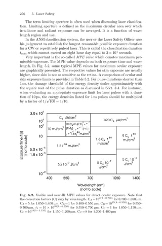
This document summarizes laser safety hazards and standards. It describes the potential eye, skin, electrical, and other hazards from laser radiation and systems. It also outlines the ANSI laser hazard classification system which categorizes lasers into four classes based on their potential to cause injury, with Class 1 being safest and Class 4 being most hazardous. Control measures are specified for each class to ensure safe use.
An Update on Safety Measures in Laser Dentistryiosrjce
IOSR Journal of Dental and Medical Sciences is one of the speciality Journal in Dental Science and Medical Science published by International Organization of Scientific Research (IOSR). The Journal publishes papers of the highest scientific merit and widest possible scope work in all areas related to medical and dental science. The Journal welcome review articles, leading medical and clinical research articles, technical notes, case reports and others.
International Journal of Computational Engineering Research(IJCER)ijceronline
International Journal of Computational Engineering Research(IJCER) is an intentional online Journal in English monthly publishing journal. This Journal publish original research work that contributes significantly to further the scientific knowledge in engineering and Technology.
Guide for Using Lead as Radiation Shieldingcanadametal
Here is the guide for the use of lead as radiation shielding for the radiation protection. Lead is highly effective for the purpose of protection from various sources of radiation. Most of the standard radiation protection systems use lead as the main material. Contact Canada Metal North America for more information.
Visit: http://www.canadametal.com/protection/
Principle of Radiation Protection- Avinesh ShresthaAvinesh Shrestha
Radiation protection is the science whose aim is to minimize the risks generated by the use of ionizing radiation. Briefly discusses The ICRP System of Radiological Protection, STRUCTURAL SHIELDING OF
IMAGING FACILITIES, APPLICATION OF INDIVIDUAL DOSE LIMTS, RADIATION EXPOSURE IN PREGNANCY, Diagnostic reference level, Personnel Protection in
Medical X-ray Imaging, Dose Optimization in CT, Radiation Protection in Nuclear Medicine.
A brief information about the SCOP protein database used in bioinformatics.
The Structural Classification of Proteins (SCOP) database is a comprehensive and authoritative resource for the structural and evolutionary relationships of proteins. It provides a detailed and curated classification of protein structures, grouping them into families, superfamilies, and folds based on their structural and sequence similarities.
Slide 1: Title Slide
Extrachromosomal Inheritance
Slide 2: Introduction to Extrachromosomal Inheritance
Definition: Extrachromosomal inheritance refers to the transmission of genetic material that is not found within the nucleus.
Key Components: Involves genes located in mitochondria, chloroplasts, and plasmids.
Slide 3: Mitochondrial Inheritance
Mitochondria: Organelles responsible for energy production.
Mitochondrial DNA (mtDNA): Circular DNA molecule found in mitochondria.
Inheritance Pattern: Maternally inherited, meaning it is passed from mothers to all their offspring.
Diseases: Examples include Leber’s hereditary optic neuropathy (LHON) and mitochondrial myopathy.
Slide 4: Chloroplast Inheritance
Chloroplasts: Organelles responsible for photosynthesis in plants.
Chloroplast DNA (cpDNA): Circular DNA molecule found in chloroplasts.
Inheritance Pattern: Often maternally inherited in most plants, but can vary in some species.
Examples: Variegation in plants, where leaf color patterns are determined by chloroplast DNA.
Slide 5: Plasmid Inheritance
Plasmids: Small, circular DNA molecules found in bacteria and some eukaryotes.
Features: Can carry antibiotic resistance genes and can be transferred between cells through processes like conjugation.
Significance: Important in biotechnology for gene cloning and genetic engineering.
Slide 6: Mechanisms of Extrachromosomal Inheritance
Non-Mendelian Patterns: Do not follow Mendel’s laws of inheritance.
Cytoplasmic Segregation: During cell division, organelles like mitochondria and chloroplasts are randomly distributed to daughter cells.
Heteroplasmy: Presence of more than one type of organellar genome within a cell, leading to variation in expression.
Slide 7: Examples of Extrachromosomal Inheritance
Four O’clock Plant (Mirabilis jalapa): Shows variegated leaves due to different cpDNA in leaf cells.
Petite Mutants in Yeast: Result from mutations in mitochondrial DNA affecting respiration.
Slide 8: Importance of Extrachromosomal Inheritance
Evolution: Provides insight into the evolution of eukaryotic cells.
Medicine: Understanding mitochondrial inheritance helps in diagnosing and treating mitochondrial diseases.
Agriculture: Chloroplast inheritance can be used in plant breeding and genetic modification.
Slide 9: Recent Research and Advances
Gene Editing: Techniques like CRISPR-Cas9 are being used to edit mitochondrial and chloroplast DNA.
Therapies: Development of mitochondrial replacement therapy (MRT) for preventing mitochondrial diseases.
Slide 10: Conclusion
Summary: Extrachromosomal inheritance involves the transmission of genetic material outside the nucleus and plays a crucial role in genetics, medicine, and biotechnology.
Future Directions: Continued research and technological advancements hold promise for new treatments and applications.
Slide 11: Questions and Discussion
Invite Audience: Open the floor for any questions or further discussion on the topic.
Comparing Evolved Extractive Text Summary Scores of Bidirectional Encoder Rep...University of Maribor
Slides from:
11th International Conference on Electrical, Electronics and Computer Engineering (IcETRAN), Niš, 3-6 June 2024
Track: Artificial Intelligence
https://www.etran.rs/2024/en/home-english/
Observation of Io’s Resurfacing via Plume Deposition Using Ground-based Adapt...Sérgio Sacani
Since volcanic activity was first discovered on Io from Voyager images in 1979, changes
on Io’s surface have been monitored from both spacecraft and ground-based telescopes.
Here, we present the highest spatial resolution images of Io ever obtained from a groundbased telescope. These images, acquired by the SHARK-VIS instrument on the Large
Binocular Telescope, show evidence of a major resurfacing event on Io’s trailing hemisphere. When compared to the most recent spacecraft images, the SHARK-VIS images
show that a plume deposit from a powerful eruption at Pillan Patera has covered part
of the long-lived Pele plume deposit. Although this type of resurfacing event may be common on Io, few have been detected due to the rarity of spacecraft visits and the previously low spatial resolution available from Earth-based telescopes. The SHARK-VIS instrument ushers in a new era of high resolution imaging of Io’s surface using adaptive
optics at visible wavelengths.
(May 29th, 2024) Advancements in Intravital Microscopy- Insights for Preclini...Scintica Instrumentation
Intravital microscopy (IVM) is a powerful tool utilized to study cellular behavior over time and space in vivo. Much of our understanding of cell biology has been accomplished using various in vitro and ex vivo methods; however, these studies do not necessarily reflect the natural dynamics of biological processes. Unlike traditional cell culture or fixed tissue imaging, IVM allows for the ultra-fast high-resolution imaging of cellular processes over time and space and were studied in its natural environment. Real-time visualization of biological processes in the context of an intact organism helps maintain physiological relevance and provide insights into the progression of disease, response to treatments or developmental processes.
In this webinar we give an overview of advanced applications of the IVM system in preclinical research. IVIM technology is a provider of all-in-one intravital microscopy systems and solutions optimized for in vivo imaging of live animal models at sub-micron resolution. The system’s unique features and user-friendly software enables researchers to probe fast dynamic biological processes such as immune cell tracking, cell-cell interaction as well as vascularization and tumor metastasis with exceptional detail. This webinar will also give an overview of IVM being utilized in drug development, offering a view into the intricate interaction between drugs/nanoparticles and tissues in vivo and allows for the evaluation of therapeutic intervention in a variety of tissues and organs. This interdisciplinary collaboration continues to drive the advancements of novel therapeutic strategies.
Seminar of U.V. Spectroscopy by SAMIR PANDASAMIR PANDA
Spectroscopy is a branch of science dealing the study of interaction of electromagnetic radiation with matter.
Ultraviolet-visible spectroscopy refers to absorption spectroscopy or reflect spectroscopy in the UV-VIS spectral region.
Ultraviolet-visible spectroscopy is an analytical method that can measure the amount of light received by the analyte.
Professional air quality monitoring systems provide immediate, on-site data for analysis, compliance, and decision-making.
Monitor common gases, weather parameters, particulates.
THE IMPORTANCE OF MARTIAN ATMOSPHERE SAMPLE RETURN.Sérgio Sacani
The return of a sample of near-surface atmosphere from Mars would facilitate answers to several first-order science questions surrounding the formation and evolution of the planet. One of the important aspects of terrestrial planet formation in general is the role that primary atmospheres played in influencing the chemistry and structure of the planets and their antecedents. Studies of the martian atmosphere can be used to investigate the role of a primary atmosphere in its history. Atmosphere samples would also inform our understanding of the near-surface chemistry of the planet, and ultimately the prospects for life. High-precision isotopic analyses of constituent gases are needed to address these questions, requiring that the analyses are made on returned samples rather than in situ.
Body fluids_tonicity_dehydration_hypovolemia_hypervolemia.pptx
LASER-SAFETY.pdf
1. 5. Laser Safety
Most parts of this chapter are adapted from the booklet “Laser Safety Guide”
(Editor: D.H.Sliney, 9th edition, 1993) published by the Laser Institute of
America, Orlando, Florida, USA. The permission obtained for reproduction
is gratefully acknowledged.
5.1 Introduction
The increasingly widespread use of lasers requires more people to become fa-
miliar with the potential hazards associated with the misuse of this valuable
new product of modern science. Applications exist in many technologies, in-
cluding material processing, construction, medicine, communications, energy
production, and national defense. Of recent importance from a safety con-
sideration, however, is the introduction of laser devices into more consumer-
oriented retail products, such as the laser scanning devices, office copy and
printing machines, and audio/visual recording devices. Most devices in these
markets emit relatively low energy levels and, consequently, are easily engi-
neered for safe use.
5.2 Laser Hazards
The basic hazards from laser equipment can be categorized as follows:
Laser Radiation Hazards
Lasers emit beams of optical radiation. Optical radiation (ultraviolet, visible,
and infrared) is termed nonionizing radiation to distinguish it from ionizing
radiation such as X-rays and gamma rays which are known to cause different
biological effects.
2. 250 5. Laser Safety
– Eye hazards: Corneal and retinal burns (or both), depending upon laser
wavelength, are possible from acute exposure; and corneal or lenticular
opacities (cataracts), or retinal injury may be possible from chronic expo-
sure to excessive levels.
– Skin hazards: Skin burns are possible from acute exposure to high levels
of optical radiation. At some specific ultraviolet wavelengths, skin carcino-
genesis may occur.
Chemical Hazards
Some materials used in lasers (i.e. excimer, dye, and chemical lasers) may be
hazardous and/or contain toxic substances. In addition, laser-induced reac-
tions can release hazardous particulate and gaseous products.
Electrical Hazards
Lethal electrical hazards may be present in all lasers, particularly in high-
power laser systems.
Other Secondary Hazards
These include:
– cryogenic coolant hazards,
– excessive noise from very high energy lasers,
– X radiation from faulty high-voltage (> 15 kV) power supplies,
– explosions from faulty optical pumps and lamps,
– fire hazards.
5.3 Eye Hazards
The ocular hazards represent a potential for injury to several different struc-
tures of the eye. This is generally dependent on which structure absorbs the
most radiant energy per volume of tissue. Retinal effects are possible when
the laser emission wavelength occurs in the visible and near infrared spectral
regions (0.4 μm to 1.4 μm). Light directly from the laser or from a specular
(mirror-like) reflection entering the eye at these wavelengths can be focused
to an extremely small image on the retina. The incidental corneal irradiance
and radiant exposure will be increased approximately 100 000 times at the
retina due to the focusing effect of the cornea and lens.
Laser emissions in the ultraviolet and far infrared spectral regions (outside
0.4 μm to 1.4 μm) produce ocular effects primarily at the cornea. However,
laser radiation at certain wavelengths may reach the lens and cause damage
to that structure.
3. 5.4 Skin Hazards 251
Optical Radiation Hazards
Effects of optical radiation at various wavelengths on various structures of the
eye are shown in Figs. 5.1a–c. Actinic-ultraviolet, at wavelengths of 180 nm
to 315 nm, is absorbed at the cornea. These wavelengths are responsible for
“welder’s flash” or photokeratitis. Near ultraviolet (UV-A) radiation between
315 nm and 400 nm is absorbed in the lens and may contribute to certain
forms of cataracts.
Radiation at visible wavelengths, 400 nm to 780 nm, and near infrared
wavelengths, 780 nm to 1400 nm, is transmitted through the ocular media
with little loss of intensity and is focused to a spot on the retina 10 μm to
20 μm in diameter. Such focusing can cause intensities high enough to dam-
age the retina. For this reason, laser radiation in the 400 nm to 1400 nm
range is termed the retinal hazard region. Wavelengths between 400 nm and
550 nm are particularly hazardous for long-term retinal exposures or expo-
sures lasting for minutes or hours. This is sometimes referred to as the blue
light hazard.
Far infrared (IR-C) radiation with wavelengths of 3 μm to 1 mm is ab-
sorbed in the front surface of the eye. However, some middle infrared (IR-B)
radiation between 1.4 μm and 3 μm penetrates deeper and may contribute to
“glass-blower’s cataract”. Extensive exposure to near infrared (IR-A) radia-
tion may also contribute to such cataracts.
The localization of injury is always the result of strong absorption in the
specific tissue for the particular wavelength.
5.4 Skin Hazards
From a safety standpoint, skin effects have been usually considered of sec-
ondary importance. However, with the more widespread use of lasers emitting
in the ultraviolet spectral region as well as higher power lasers, skin effects
have assumed greater importance.
Erythema1
, skin cancer, and accelerated skin aging are possible in the
230 nm to 380 nm wavelength range (actinic ultraviolet). The most severe
effects occur in the UV-B (280–315 nm). Increased pigmentation can result
following chronic exposures in the 280 nm to 480 nm wavelength range. At
high irradiances, these wavelengths also produce “long-wave” erythema of
the skin. In addition, photosensitive reactions are possible in the 310 nm to
400 nm (near ultraviolet) and 400 nm to 600 nm (visible) wavelength regions.
The most significant effects in the 700 nm to 1000 nm range (infrared) will be
skin burns and excessive dry skin.
1
Sunburn.
4. 252 5. Laser Safety
Fig. 5.1. (a) Absorption sites of visible and near infrared radiation. (b) Absorp-
tion sites of middle infrared, far infrared, and middle ultraviolet radiation. (c)
Absorption sites of near ultraviolet radiation
5. 5.6 Laser Safety Standards and Hazard Classification 253
5.5 Associated Hazards from High Power Lasers
Some applications of high-power lasers, especially in materials processing,
can give rise to respiratory hazards. Laser welding, cutting, and drilling pro-
cedures can create potentially hazardous fumes and vapors. Fortunately, the
same localized and general ventilation procedures developed for similar con-
ventional operations apply to this type of laser application.
The most lethal hazards associated with the laser involves electricity.
There have been several fatal accidents associated with lasers due to electro-
cution. These occurred when commonly accepted safety procedures were not
followed when individuals were working with dangerous, high-voltage com-
ponents of a laser system. Proper electrical hazards controls should be used
at all times when working with laser systems.
Fire hazards may exist with some high-power laser devices, normally those
with continuous wave (CW) lasers having an ouput power above 0.5 W. An-
other hazard sometimes associated with high-power laser systems involves
the use of cryogenic coolants used in the laser system. Skin contact can cause
burns, improper plumbing can cause explosions, and insufficient ventilation
can result in the displacement of oxygen in the air by liquefied gas vaporizing
(most commonly nitrogen). Cryogenic hazards are normally, but not exclu-
sively, limited to research laboratories. Noise hazards are rarely present in
laser operations.
5.6 Laser Safety Standards and Hazard Classification
The basic approach of virtually all laser safety standards has been to classify
lasers by their hazard potential which is based upon their optical emission.
The next step is to specify control measures which are commensurate with
the relative hazard classification. In other words, the laser is classified based
upon the hazard it presents, and for each classification a standard set of
control measures applies. In this manner, unnecessary restrictions are not
placed on the use of many lasers which are engineered to assure safety.
This philosophy has given rise to a number of specific classification
schemes such as the one employed in the American National Standards Insti-
tute’s (ANSI) Z136.1 Safe Use of Lasers (1993) standard. This standard was
developed by the accredited standards committee Z136, and the Laser Insti-
tute of America is the secretariat. The standard has been used as a source
by many organizations including the Occupational Health and Safety Agency
(OSHA) and the American Conference of Governmental Industrial Hygienists
(ACGIH) in developing their laser safety guidelines2
.
2
Meanwhile, major parts of the ANSI classification scheme have been adapted by
most European safety organizations, as well.
6. 254 5. Laser Safety
The ANSI scheme has four hazard classifications. The classification is
based upon the beam output power or energy from the laser (emission) if
it is used by itself. If the laser is a component within a laser system where
the raw beam does not leave the enclosure, but instead a modified beam is
emitted, the modified beam is normally used for classification. Basically, the
classification scheme is used to describe the capability of the laser or laser
system to produce injury to personnel. The higher the classification number,
the greater is the potential hazard. Brief descriptions of each laser class are
given as follows:
– Class 1 denotes lasers or laser systems that do not, under normal operating
conditions, pose a hazard.
– Class 2 denotes low-power visible lasers or visible laser systems which, be-
cause of the normal human aversion response (i.e. blinking, eye movement,
etc.), do not normally present a hazard, but may present some potential
for hazard if viewed directly for extended periods of time (like many con-
ventional light sources). Safety glasses are required for prolonged viewing
only.
– Class 3a denotes the lowest class of lasers or laser systems that always
require protective eyewear. These lasers would not injure the eye if viewed
for only momentary periods (e.g. within the aversion response period of
approximately 0.25 s) with the unaided eye, but may present a greater
hazard if viewed using collecting optics or if viewed without the possibility
of an aversion response (as for UV or IR radiation).
– Class 3b denotes lasers or laser systems that can produce a hazard if viewed
directly. This includes intrabeam viewing of specular reflections. Normally,
Class 3b lasers will not produce a hazardous diffuse reflection. Protective
eyewear is always required.
– Class 4 denotes lasers and laser systems that produce a hazard not only
from direct or specular reflections, but may also produce hazardous diffuse
reflections. Such lasers may produce significant skin hazards as well as fire
hazards. Protective eyewear is always required.
Although the process of laser hazard evaluation does not rely entirely on
the laser classification, the laser classification must be known. If the laser
classification has not been provided by the manufacturer (as usually required
by law), the class can be determined by measurement and/or calculation.
A list of typical laser classifications is found in Table 5.1. Since the relative
hazard of a laser may also vary depending upon use and/or environmental
effects, measurements and/or calculations may be necessary to determine the
degree of hazard in such cases.
8. 256 5. Laser Safety
The term limiting aperture is often used when discussing laser classifica-
tion. Limiting aperture is defined as the maximum circular area over which
irradiance and radiant exposure can be averaged. It is a function of wave-
length region and use.
In the ANSI classification system, the user or the Laser Safety Officer uses
his judgement to establish the longest reasonable possible exposure duration
for a CW or repetitively pulsed laser. This is called the classification duration
tmax which cannot exceed an eight hour day equal to 3 × 10⁴
seconds.
Very important is the so-called MPE value which denotes maximum per-
missible exposure. The MPE value depends on both exposure time and wave-
length. In Fig. 5.2, some typical MPE values for maximum ocular exposure
are graphically presented. The respective values for skin exposure are usually
higher, since skin is not as sensitive as the retina. A comparison of ocular and
skin exposure limits is provided in Table 5.2. For pulse durations shorter than
1 ns, the damage threshold of the energy density scales approximately with
the square root of the pulse duration as discussed in Sect. 3.4. For instance,
when evaluating an appropriate exposure limit for laser pulses with a dura-
tion of 10 ps, the energy densities listed for 1 ns pulses should be multiplied
by a factor of 1/
√
100 = 1/10.
Fig. 5.2. Visible and near-IR MPE values for direct ocular exposure. Note that
the correction factors (C) vary by wavelength. CA =102(λ−0.700)
for 0.700–1.050 μm.
CA =5 for 1.050–1.400 μm. CB =1 for 0.400–0.550 μm. CB =1015(λ−0.550)
for 0.550–
0.700 μm. t1 = 10 × 1020(λ−0.550)
for 0.550–0.700 μm. CC = 1 for 1.050–1.150 μm.
CC =1018(λ−1.150)
for 1.150–1.200 μm. CC =8 for 1.200–1.400 μm
9. 5.6 Laser Safety Standards and Hazard Classification 257
Table 5.2. Ocular and skin exposure limits of some representative lasers. Repetitive
pulses at rates less than one pulse per second were assumed for any repetitive
exposures. Higher repetition rates require more adjustment of the exposure limits.
τ: pulse duration
Laser type Wavelength (nm) Ocular exposure limita
(MPE value)
Argon ion 488/514 0.5 μJ/cm2
for 1 ns to 18 μs
1.8 τ3/4
mJ/cm2
for 18 μs to 10 s
10 mJ/cm2
for 10 s to 10 000 s
1 μW/cm2
for greater durations
He-Ne 632.8 0.5 μJ/cm2
for 1 ns to 18 μs
1.8 τ3/4
mJ/cm2
for 18 μs to 430 s
170 mJ/cm2
for 430 s to 10 000 s
17 μW/cm2
for greater durations
Nd:YAG 1064 5 μJ/cm2
for 1 ns to 50 μs
9 τ3/4
mJ/cm2
for 50 μs to 1 000 s
1.6 mW/cm2
for greater durations
Diode 910 1.3 μJ/cm2
for 1 ns to 18 μs
4.5 τ3/4
mJ/cm2
for 18 μs to 1 000 s
0.8 mW/cm2
for greater durations
CO2 10600 10 mJ/cm2
for 1 ns to 100 ns
0.56 τ1/4
J/cm2
for 100 ns to 10 s
0.1 W/cm2
for greater durations
Laser type Wavelength (nm) Skin exposure limitb
(MPE value)
Argon ion 488/514 0.02 J/cm2
for 1 ns to 100 ns
1.1 τ1/4
J/cm2
for 100 ns to 10 s
0.2 W/cm2
for greater durations
He-Ne 632.8 0.02 J/cm2
for 1 ns to 100 ns
1.1 τ1/4
J/cm2
for 100 ns to 10 s
0.2 W/cm2
for greater durations
Nd:YAG 1064 0.1 J/cm2
for 1 ns to 100 ns
5.5 τ1/4
J/cm2
for 100 ns to 10 s
1.0 W/cm2
for greater durations
Diode 910 0.05 J/cm2
for 1 ns to 100 ns
2.8 τ1/4
J/cm2
for 100 ns to 10 s
0.5 W/cm2
for greater durations
CO2 10600 10 mJ/cm2
for 1 ns to 100 ns
0.56 τ1/4
J/cm2
for 100 ns to 10 s
0.1 W/cm2
for greater durations
a
The exposure limit is averaged over a 7 mm aperture for wavelengths between
400 nm and 1400 nm, and over 1.0 mm for the CO2 laser wavelength at 10.6 μm.
b
The exposure limit is defined for a 3.5 mm measuring aperture.
10. 258 5. Laser Safety
Any completely enclosed laser is classified as a Class 1 laser if emissions
from the enclosure cannot exceed the MPE values under any conditions inher-
ent in the laser design. During service procedures, however, the appropriate
control measures are temporarily required for the class of laser contained
within the enclosure. In the United States, a Federal government safety stan-
dard for laser products, which regulates laser manufacturers, was developed
by the Center for Devices and Radiological Health (CDRH).
5.7 Viewing Laser Radiation
From a safety point of view, the laser can be considered as a highly collimated
source of extremely intense monochromatic electromagnetic radiation. Due to
these unique beam properties, most laser devices can be considered as a point
source of great brightness. Conventional light sources or a diffuse reflection
of a Class 2 or Class 3 laser beam are extended sources of very low brightness
because the light radiates in all directions. This is of considerable consequence
from a hazard point of view, since the eye will focus the rays (400–1400 nm)
from a point source to a small spot on the retina while the rays from an
extended source will be imaged, in general, over a much larger area. Only
when one is relatively far away from a diffuse reflection (far enough that the
eye can no longer resolve the image) will the diffuse reflection approximate
a “point source”. Diffuse reflections are only of importance with extremely
high-power Class 4 laser devices emitting visible and IR-A radiation between
400 nm and 1400 nm.
Different geometries of ocular exposure are demonstrated in Figs. 5.3–5.6.
Intrabeam viewing of the direct (primary) laser beam is shown in Fig. 5.3.
This type of viewing is most hazardous. Intrabeam viewing of a specularly
reflected (secondary) beam from a flat surface is illustrated in Fig. 5.4. Spec-
ular reflections are most hazardous when the reflecting surface is either flat
or concave. On the other hand, intrabeam viewing of a specularly reflected
(secondary) beam from a convex surface is less hazardous, since the diver-
gence of the beam has increased after reflection (see Fig. 5.5). Finally, Fig. 5.6
illustrates extended source viewing of a diffuse reflection. Usually, diffuse re-
flections are not hazardous except with very high power Class 4 lasers.
Fig. 5.3. Intrabeam viewing of a direct beam
11. 5.7 Viewing Laser Radiation 259
Fig. 5.4. Intrabeam viewing of a specularly reflected beam from a flat surface
Fig. 5.5. Intrabeam viewing of a specularly reflected beam from a curved surface
Fig. 5.6. Extended source viewing of a diffuse reflection
12. 260 5. Laser Safety
5.8 Eye Protection
Although engineering controls, such as enclosure of the laser beam, are far
more preferable than the use of laser eye protection, there are instances when
the use of laser eye protection is the most effective safety measure. It is
important that the eye protection be clearly marked to insure that it is not
used for protection against laser wavelengths for which it is not intended. If
the eye protection is used outdoors it should employ curved-surface lenses to
eliminate the additional hazard of generating collimated specular reflections.
Table 5.3 provides a simplified approach for determining the optical density
requirements for contemplated exposure conditions. A detailed discussion of
safe eye protection was given by Sliney and Wolbarsht (1980).
Specifying Protective Filters
How does one properly specify protective eyewear? The optical density OD(λ)
of protective filters at a specific wavelength λ is given by the equation
OD(λ) = log10
H0
MPE
,
where H0 is the anticipated worst case exposure (expressed usually in units of
W/cm2
for CW sources or J/cm2
for pulsed sources). The MPE is expressed
in units identical to those of H0.
As an example, consider a single-pulse Nd:YAG laser operating at a wave-
length of 1064 nm with an emergent beam diameter of 2 mm and a beam
divergence of 1.0 mrad. The output is a TEM00 pulse of 80 mJ delivered in
a pulse duration of 15 ns. The MPE is 5 × 10⁻⁶
J/cm2
. The most likely ex-
posure is intrabeam viewing of the raw beam, i.e. Hraw 2.55 J/cm2
(the
fluence of the 80 mJ pulse in the 2 mm beam diameter). Since ANSI values of
the MPEs are determined using a limiting aperture of 7 mm (maximum pupil
size), the value of H0 for beams smaller than 7 mm should be calculated as
though the beam were distributed over the limiting aperture (which is the
worst case exposure, since larger beam diameters are focused to smaller spot
sizes on the retina), thus
H0 =
80 mJ
π (0.35 cm)2
0.21 J/cm
2
.
The required optical density would be
OD(λ) = log10
0.21
5×10⁻⁶
4.6 at λ = 1064 nm .
Thus, a direct exposure into the eye would require a filter density of nearly
5 to reduce the incident radiant exposure to the “safe” MPE level.
13. 5.8 Eye Protection 261
Table 5.3. Simplified method for selecting laser eye protection intrabeam view-
ing for wavelengths between 400 nm and 1400 nm. Data from American National
Standards Institute’s (ANSI) Z136.1 (1993)
Q-switched lasers Non-Q-switched lasers Attenuation
(1 ns to 0.1 ms) (0.4 ms to 10 ms)
Maximum Maximum Maximum Maximum Attenuation OD
output radiant output radiant factor
energy exposure energy exposure
(J) (J/cm2
) (J) (J/cm2
)
10 20 100 200 108
8
1 2 10 20 107
7
10−1
2 × 10⁻¹
1 2 106
6
10−2
2 × 10⁻²
10−1
2 × 10⁻¹
105
5
10−3
2 × 10⁻³
10−2
2 × 10⁻²
104
4
10−4
2 × 10⁻⁴
10−3
2 × 10⁻³
103
3
10−5
2 × 10⁻⁵
10−4
2 × 10⁻⁴
102
2
10−6
2 × 10⁻⁶
10−5
2 × 10⁻⁵
101
1
CW lasers CW lasers Attenuation
momentary long-term staring
(0.25 s to 10 s) (greater than 3 hours)
Maximum Maximum Maximum Maximum Attenuation OD
output irradiance output irradiance factor
power power
(W) (W/cm2
) (W) (W/cm2
)
NR NR NR NR NR NR
NR NR NR NR NR NR
NR NR 1 2 106
6
NR NR 10−1
2 × 10⁻¹
105
5
10 20 10−2
2 × 10⁻²
104
4
1 2 10−3
2 × 10⁻³
103
3
10−1
2 × 10⁻¹
10−4
2 × 10⁻⁴
102
2
10−2
2 × 10⁻²
10−5
2 × 10⁻⁵
101
1
OD: optical density.
NR: not recommended.
14. 262 5. Laser Safety
5.9 Laser Beam Calculations
Only two laser beam calculations are provided in this section, since these are
the most commonly encountered.
The emergent beam diameter is an important parameter in classifying
a laser and in evaluating a hazard to the eye or skin. Most laser manufacturers
specify output beam power or energy and generally provide the emergent
beam diameter. It is often left to the user to calculate the output irradiance
(intensity) in units of W/cm2
and radiant exposure (fluence) in units of J/cm2
for comparison with protection standards like the MPE values defined by
ANSI.
The beam diameter specified by many laser manufacturers is the diameter
of an aperture that will just accept 90 % of the output energy of a pulsed
laser or 87 % of the output power of a CW laser having a Gaussian beam
(also known as 1/e2
points). Regrettably for safety purposes it is necessary
to calculate or measure peak radiant exposure or irradiance for a large beam
diameter, or the fraction of power or energy passing through a specified “lim-
iting aperture”.
For ocular exposure limits in the visible and near infrared (400–1400 nm)
spectral region, the limiting aperture is 7 mm corresponding to the dilated
pupil. For ultraviolet and most of the infrared spectral regions, this aperture is
normally 1 mm or 3.5 mm. Only for the extreme infrared region (0.1–1.0 mm),
a limiting aperture of 1 cm is assumed.
Using a laser power meter at two distances z1 and z2 with a fixed aper-
ture, one can determine the change in beam radius w to calculate the beam
divergence Φ by means of
Φ =
2w(z2) − 2w(z1)
z2 − z1
=
2Δw
Δz
,
where w and z are in units of cm, and Φ is in units of radians3
.
The other beam calculation concerns the central-beam values of intensity
and fluence, since they are usually the highest and thus determine potential
hazards. Often, these values are not provided in the specification of a laser.
However, if the laser has a Gaussian-shaped beam profile and emits in the
fundamental TEM00 mode, the corresponding central-beam values can be
obtained from the beam radius w1/e specified at the 1/e points. This beam
radius is defined as the radius of an aperture that will just accept 63 % of the
incident power, i.e. 1/e of the incident power is blocked.
3
More accurately, the beam radius of a Gaussian beam changes with distance
according to a hyperbolic function rather than linearly. When the beam waist
occurs at or near the exit port of the laser, the correct equation for the beam
radius is w(z) =
w2
0 + (Φ/2)2 z2, where w0 is the smallest beam waist. Only
at distances far apart from the smallest beam waist may w0 be omitted without
loss of accuracy.
15. 5.10 Questions to Chapter 5 263
The relations for the central-beam intensity I0 and fluence E0 can then be
expressed by
I0 =
P
π w 2
1/e
,
E0 =
Q
π w 2
1/e
,
where P is the radiant power in units of W, and Q is the radiant energy in
units of J.
Often, the beam radius is specified at the 1/e2
points rather than at
the 1/e points, so that the above relations would provide lower values than
the central-beam values. In this case, the radius specified at the 1/e2
points
should be divided by
√
2 to obtain the corresponding 1/e value, hence
w1/e =
w1/e2
√
2
0.707 w1/e2 .
5.10 Questions to Chapter 5
Q5.1. Which is the lowest laser class that always requires the use of safety
glasses?
A: Class 2. B: Class 3a. C: Class 3b.
Q5.2. Which radiation is able to burn the fovea?
A: UV-B. B: VIS. C: IR-C.
Q5.3. Which radiation is able to cause skin cancer?
A: UV-B. B: VIS. C: IR-C.
Q5.4. Typical CW lasers in Class 4 have an output power
A: 0.5 W. B: 0.5 W. C: 1 kW.
Q5.5. When comparing the MPE values for eyes and skin, then
A: MPEeye MPEskin. B: MPEeye = MPEskin. C: MPEeye MPEskin.
Q5.6. Which are the three basic hazards from laser equipment?
Q5.7. Why is a collinear, visible or near infrared laser beam most dangerous
to our vision?
Q5.8. Why is there no ultraviolet or infrared Class 2 laser?
Q5.9. What laser class is a high power 100 W Nd:YAG laser at a wavelength
of 1064 nm that is completely enclosed?
Q5.10. An ophthalmologist uses a 200 mW argon ion laser at a wavelength
of 514 nm to perform a retinal coagulation. The procedure takes ten seconds.
What is the optical density needed in his eyewear to protect his eyes from
accidental damage (consider Fig. 5.2)?