
Recommended
Recommended
More Related Content
What's hot
What's hot (20)
Similar to Setup Instructions for Stratix 5400 & 5700 switches with NAT
Similar to Setup Instructions for Stratix 5400 & 5700 switches with NAT (20)
Setup Instructions for Stratix 5400 & 5700 switches with NAT
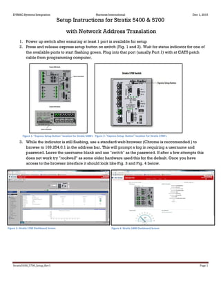
- 1. DYNAC Systems Integration Hartness International Dec 1, 2015 Stratix5400_5700_Setup_Rev1 Page 1 Setup Instructions for Stratix 5400 & 5700 with Network Address Translation 1. Power up switch after ensuring at least 1 port is available for setup 2. Press and release express setup button on switch (Fig. 1 and 2). Wait for status indicator for one of the available ports to start flashing green. Plug into that port (usually Port 1) with at CAT5 patch cable from programming computer. 3. While the indicator is still flashing, use a standard web browser (Chrome is reccomended ) to browse to 169.254.0.1 in the address bar. This will prompt a log in requiring a username and password. Leave the username blank and use "switch" as the password. If after a few attempts this does not work try "rockwell" as some older hardware used this for the default. Once you have access to the browser interface it should look like Fig. 3 and Fig. 4 below. Figure 3: Stratix 5700 Dashboard Screen Figure 4: Stratix 5400 Dashboard Screen Figure 2: "Express Setup Button" location For Stratix 5700'sFigure 1: "Express Setup Button" location for Stratix 5400's
- 2. DYNAC Systems Integration Hartness International Dec 1, 2015 Stratix5400_5700_Setup_Rev1 Page 2 4. Next we will set the chosen IP address. Under Configure select Express Setup on the right hand column of the page (Fig. 5). Here you will set the switches Native IP address as well as VLAN settings. once submitted initial setup of the switch is complete. Network Address Translation Setup 5. Now we will set up NAT functionality. In the following figures I will using the example of a NAT between the Line Control Network and Labeler where the Labeler has only a private network that is on a completely different subnet from the Line P2P as shown in Fig. 6. 6. It is Important to note that theses switches are designed to be used by machine centers to talk from a local or private network to a public network to a select few devices. This can be confusing as we generally consider our communications network to be the public whereas when setting up NAT function, the line control or "Public" subnet should be used wherever it says private in the NAT setup and vice versa for the machine centers "Private" network. Put simply just remember that the nomenclature is flipped from the line control perspective. Figure 5: Stratix 5700 Express Setup screen Figure 6: Line Control Peer to Peer network with NAT to Labeler local network
- 3. DYNAC Systems Integration Hartness International Dec 1, 2015 Stratix5400_5700_Setup_Rev1 Page 3 7. Under the Configure tab select NAT, which will bring up the NAT Instance Editor. Here there are three tabs, General, peer to peer, and Advanced. Start with the general Tab. 8. Here we will put the address we have assigned on our subnet for the target device as the private address and the devices actual address as the public. Every device that needs to communicate with the target device must have a NATed IP address configured here. 9. This should include at a minimum; Line Control PLC, Stratix switch, and any programming devices. (Fig. 8) Also be aware you may need to set the default gateway on the target device to the Stratix native IP address. Figure 7: NAT Instance Editor General - Prior to configuration of any new NAT function Figure 8: Stratix 5400 NAT General Configuration Tab. - 10.0.2.X is the line control subnet, 90 is the PLC, 254 is the switch, and 237 is the programing computer. Each is NATed to specific address on the Labelers 172.16.32.X network.
- 4. DYNAC Systems Integration Hartness International Dec 1, 2015 Stratix5400_5700_Setup_Rev1 Page 4 10. In the Public to Private tab do the same as you were in the General tab but in this instance you are translating from the target device's network to the Line Control network. (Fig.9) 11. Lastly ensure that everything in the advanced tab is configured as Pass-Through then submit the configurations. Lastly we need to configure the Smartports which can be found under the configure menu on the Stratix main toolbar. For every port being used to NAT from another network you need to configure the Smartports so that the data is managed appropriately. In most of our applications this will be done by assigning the appropriate port as a Multiport Automation device as seen in Fig. 10. Figure 9: Stratix 5400 P2P Configuration Tab. - 172.16.32.10 is the Labelers native address with .155 and .152 being reversed translations of the switch and programing computer from the general tab, any device requiring 2way comunication with the target device must be configured in both the P2P tab and the general tab.
- 5. DYNAC Systems Integration Hartness International Dec 1, 2015 Stratix5400_5700_Setup_Rev1 Page 5 12. Once this is complete you should attempt to ping the target device using cmd.exe. if the ping returns data then you have successfully configured your Startix switch with NAT functionality Figure 10: Smartports role configuration screen.