
Recommended
Recommended
More Related Content
Similar to L-5, Screwed Fasteners.pptx
Similar to L-5, Screwed Fasteners.pptx (20)
Recently uploaded
Recently uploaded (20)
L-5, Screwed Fasteners.pptx
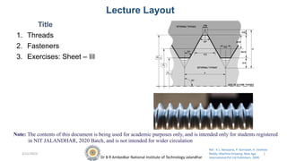
- 1. Dr B R Ambedkar National Institute of Technology Jalandhar Ref.: K.L. Narayana, P. Kannaiah, K. Venketa Reddy. Machine Drawing. New Age International Pvt Ltd Publishers, 2009. Lecture Layout Title 1. Threads 2. Fasteners 3. Exercises: Sheet – III 2/21/2023 1 Note: The contents of this document is being used for academic purposes only, and is intended only for students registered in NIT JALANDHAR, 2020 Batch, and is not intended for wider circulation
- 2. Dr B R Ambedkar National Institute of Technology Jalandhar Ref.: K.L. Narayana, P. Kannaiah, K. Venketa Reddy. Machine Drawing. New Age International Pvt Ltd Publishers, 2009. Fasteners • A machine element used for holding or joining two or more parts of a machine or structure is known as a fastener. • The fasteners are of two types : 1. Permanent and 2. Removable (temporary). • Riveting and welding processes are used for fastening permanently. • Screwed fasteners such as bolts, studs and nuts in combination, machine screws, set screws, etc., and keys, cotters, couplings, etc., are used for fastening components that require frequent assembly and dissembly. 2/21/2023 2
- 3. Dr B R Ambedkar National Institute of Technology Jalandhar Ref.: K.L. Narayana, P. Kannaiah, K. Venketa Reddy. Machine Drawing. New Age International Pvt Ltd Publishers, 2009. Screw Thread Nomenclature • A screw thread is obtained by cutting a continuous helical groove on a cylindrical surface (external thread). 2/21/2023 3 Pitch diameter This is the diameter of an imaginary cylinder, passing through the threads at the points where the thread width is equal to the space between the threads. Lead It is the distance a screw advances axially in one turn. Flank Flank is the straight portion of the surface, on either side of the screw thread. Thread angle This is the angle included between the flanks of the thread, measured in an axial plane
- 4. Dr B R Ambedkar National Institute of Technology Jalandhar Ref.: K.L. Narayana, P. Kannaiah, K. Venketa Reddy. Machine Drawing. New Age International Pvt Ltd Publishers, 2009. Forms of Threads • Bureau of Indian Standards (BIS) adapts ISO (International Organisation for Standards) metric threads which are adapted by a number of countries apart from India 2/21/2023 4
- 5. Dr B R Ambedkar National Institute of Technology Jalandhar Ref.: K.L. Narayana, P. Kannaiah, K. Venketa Reddy. Machine Drawing. New Age International Pvt Ltd Publishers, 2009. Other Thread Profiles • V-Thread (sharp): This thread profile has a larger contact area, providing more frictional resistance to motion. Hence, it is used where effective positioning is required. It is also used in brass pipe work. • British Standard Whitworth (BSW) Threads: This thread form is adopted in Britain in inch units. The profile has rounded ends, making it less liable to damage than sharp V-thread. • Buttress Thread: This thread is a combination of V-and square threads. It exhibits the advantages of square thread, like the ability to transmit power and low frictional resistance, with the strength of the V-thread. It is used where power transmission takes place in one direction only such as screw press, quick acting carpenter’s vice, etc. • Square Thread: Square thread is an ideal thread form for power transmission. In this, as the thread flank is at right angle to the axis, the normal force between the threads, acts parallel to the axis, with zero radial component. This enables the nut to transmit very high pressures, as in the case of a screw jack and other similar applications • ACME Thread: It is a modified form of square thread. It is much stronger than square thread because of the wider base and it is easy to cut. The inclined sides of the thread facilitate quick and easy engagement and disengagement as for example, the split nut with the lead screw of a lathe. • Worm Thread: Worm thread is similar to the ACME thread, but is deeper. It is used on shafts to carry power to worm wheels. 2/21/2023 5
- 6. Dr B R Ambedkar National Institute of Technology Jalandhar Ref.: K.L. Narayana, P. Kannaiah, K. Venketa Reddy. Machine Drawing. New Age International Pvt Ltd Publishers, 2009. Other Thread Profiles 2/21/2023 6 Exercise 1: Types of thread profiles • Figure 5.3, Page – 79
- 7. Dr B R Ambedkar National Institute of Technology Jalandhar Ref.: K.L. Narayana, P. Kannaiah, K. Venketa Reddy. Machine Drawing. New Age International Pvt Ltd Publishers, 2009. Thread designation • The diameter-pitch combination of an ISO metric screw thread is designated by the letter ‘M’ followed by the value of the nominal diameter and pitch, the two values being separated by the sign ‘×’. For example, a diameter pitch combination of nominal diameter 10 mm and pitch 1.25 mm is designated as M10 × 1.25. • If there is no indication of pitch in the designation, it shall mean the coarse pitch. For example, M 10 means that the nominal diameter of the thread is 10 mm and pitch is 1.5 mm. • SQ 40 × 10 – SQUARE thread of nominal diameter 40 mm and pitch 10 mm • ACME 40 × 8 – ACME thread of nominal diameter 40 mm and pitch 8 mm • WORM 40 × 10 – WORM thread of nominal diameter 40 mm and pitch 10 mm 2/21/2023 7
- 8. Dr B R Ambedkar National Institute of Technology Jalandhar Ref.: K.L. Narayana, P. Kannaiah, K. Venketa Reddy. Machine Drawing. New Age International Pvt Ltd Publishers, 2009. Multi-Start Threads • Multi-start threads are also used wherever quick action is desired, as in fountain pens, automobile starters, arbor press spindles, hydraulic valve spindles, etc • For a double start thread, lead is equal to twice the pitch and for a triple start thread, lead is equal to thrice the pitch. 2/21/2023 8
- 9. Dr B R Ambedkar National Institute of Technology Jalandhar Ref.: K.L. Narayana, P. Kannaiah, K. Venketa Reddy. Machine Drawing. New Age International Pvt Ltd Publishers, 2009. Right hand & Left hand threads • Screw threads may be right hand or left hand, depending on the direction of the helix. • A right hand thread is one which advances into the nut, when turned in a clockwise direction and a left hand thread is one which advances into the nut when turned in a counter clockwise direction. • An abbreviation LH is used to indicate a left hand thread. Unless otherwise stated, a thread should be considered as a right hand one. 2/21/2023 9
- 10. Dr B R Ambedkar National Institute of Technology Jalandhar Ref.: K.L. Narayana, P. Kannaiah, K. Venketa Reddy. Machine Drawing. New Age International Pvt Ltd Publishers, 2009. Representation of Threads • For time saving, conventional representation of external and internal threads as recommended by BIS • Crests of threads are indicated by a continuous thick line and the roots, by a continuous thin line. 2/21/2023 10
- 11. Dr B R Ambedkar National Institute of Technology Jalandhar Ref.: K.L. Narayana, P. Kannaiah, K. Venketa Reddy. Machine Drawing. New Age International Pvt Ltd Publishers, 2009. Representation of Threads 2/21/2023 11
- 12. Dr B R Ambedkar National Institute of Technology Jalandhar Ref.: K.L. Narayana, P. Kannaiah, K. Venketa Reddy. Machine Drawing. New Age International Pvt Ltd Publishers, 2009. Representation of Threaded parts in Assembly Figure 5.10: a) schematic representation 2/21/2023 12 b) representation of threads in engagement Figure 5.10 a represents the internal threaded part in section; however, the external threaded one is shown unsectioned. In Figs. 5.10b, the external threaded parts are shown covering the internal threaded parts and should not be shown as hidden by them.
- 13. Dr B R Ambedkar National Institute of Technology Jalandhar Ref.: K.L. Narayana, P. Kannaiah, K. Venketa Reddy. Machine Drawing. New Age International Pvt Ltd Publishers, 2009. Bolted Joints • For nuts, hexagonal shape is preferred to the square one, as it is easy to tighten even in a limited space. This is because, with only one-sixth of a turn, the spanner can be re-introduced in the same position. • However, square nuts are used when frequent loosening and tightening is required, for example on job holding devices like vices, tool posts in machines, etc. 2/21/2023 13
- 14. Dr B R Ambedkar National Institute of Technology Jalandhar Ref.: K.L. Narayana, P. Kannaiah, K. Venketa Reddy. Machine Drawing. New Age International Pvt Ltd Publishers, 2009. Method of drawing Hexagonal (Bolt head) Nut Following approximate method is used to save the draughting time: 2/21/2023 Method 2 – ISO (Fig. 5.12) Empirical relations : • Major or nominal diameter of bolt = D • Thickness of nut, T = D • Width of nut across flat surfaces, W (A/F) = 1.5D + 6 mm (D<12mm); = 1.5D + 3 mm (D>12mm); = 1.5D • Width of the nut across corners, A/C= 2D • Radius of chamfer, R = 1.5D 14 ACROSS CORNERS A/C ACROSS FLATS A/F
- 15. Dr B R Ambedkar National Institute of Technology Jalandhar Ref.: K.L. Narayana, P. Kannaiah, K. Venketa Reddy. Machine Drawing. New Age International Pvt Ltd Publishers, 2009. Method of drawing Hexagonal (Bolt head) Nut 2/21/2023 15 Pritam Singh Gill. A Textbook of Machine Drawing. SK Kataria & Sons, 2013 Exercise 2: Hexagonal nut • Figure 18.25 Page – 451 (D=20mm)
- 16. Dr B R Ambedkar National Institute of Technology Jalandhar Ref.: K.L. Narayana, P. Kannaiah, K. Venketa Reddy. Machine Drawing. New Age International Pvt Ltd Publishers, 2009. Method of drawing Hexagonal (Bolt head) Nut 2/21/2023 16 Fig. 5.13 Method of drawing views of a hexagonal nut (Method II) Exercise 2: Hexagonal nut • Figure 5.12 Page – 86 (D=20mm)
- 17. Dr B R Ambedkar National Institute of Technology Jalandhar Ref.: K.L. Narayana, P. Kannaiah, K. Venketa Reddy. Machine Drawing. New Age International Pvt Ltd Publishers, 2009. Method of drawing Hexagonal (Bolt head) Nut 1. Draw the view from above by drawing a circle of diameter, W and describe a regular hexagon on it, by keeping any two parallel sides of the hexagon, horizontal. 2. Project the view from the front, and the view from side, and mark the height equal to D. 3. With radius R, draw the chamfer arc 2-1-3 passing through the point 1 in the front face. 4. Mark points 4 and 5, lying in-line with 2 and 3. 5. Locate points 8,9 on the top surface, by projecting from the view from above. 6. Draw the chamfers 4–8 and 5–9. 7. Locate points 6 and 7, lying at the middle of the outer two faces. 8. Draw circular arcs passing through the points 4, 6, 2 and 3, 7, 5, after determining the radius R1 geometrically. 9. Project the view from the side and locate points 10, 11 and 12. 10. Mark points 13 and 14, lying at the middle of the two faces (view from the side). 11. Draw circular arcs passing through the points 10, 13, 11 and 11, 14, 12, after determining the radius R2 geometrically. • It may be noted that in the view from the front, the upper outer corners appear chamfered. In the view from the side, where only two faces are seen, the corners appear square. 2/21/2023 17
- 18. Dr B R Ambedkar National Institute of Technology Jalandhar Ref.: K.L. Narayana, P. Kannaiah, K. Venketa Reddy. Machine Drawing. New Age International Pvt Ltd Publishers, 2009. WASHER • It is used to give a perfect seating for the nut and to distribute the tightening force uniformly to the parts under the joint. • It also prevents the nut from damaging the metal surface under the joint 2/21/2023 18
- 19. Dr B R Ambedkar National Institute of Technology Jalandhar Ref.: K.L. Narayana, P. Kannaiah, K. Venketa Reddy. Machine Drawing. New Age International Pvt Ltd Publishers, 2009. STUD BOLT OR STUD 2/21/2023 19
- 20. Dr B R Ambedkar National Institute of Technology Jalandhar Ref.: K.L. Narayana, P. Kannaiah, K. Venketa Reddy. Machine Drawing. New Age International Pvt Ltd Publishers, 2009. 2/21/2023 20 hexagonal nut with a collar or flange hexagonal nut with a cylindrical cap at the top spherical dome at the top cylindrical in shape, with holes drilled laterally in the curved surface in form of a ring, with slots in the curved surface This nut is used when frequent removal is required, such as inspection covers, lids, etc
- 21. Dr B R Ambedkar National Institute of Technology Jalandhar Ref.: K.L. Narayana, P. Kannaiah, K. Venketa Reddy. Machine Drawing. New Age International Pvt Ltd Publishers, 2009. Machine Screws • Machine screws are usually smaller in size, compared to cap screws 2/21/2023 21
- 22. Dr B R Ambedkar National Institute of Technology Jalandhar Ref.: K.L. Narayana, P. Kannaiah, K. Venketa Reddy. Machine Drawing. New Age International Pvt Ltd Publishers, 2009. Set Screws • These are used to prevent relative motion between two rotating parts, such as the movement of pulley on shaft • For longer life, set screws are made of steel and case hardened. 2/21/2023 22 Figure 5.26: Different forms of set screws
- 23. Dr B R Ambedkar National Institute of Technology Jalandhar Ref.: K.L. Narayana, P. Kannaiah, K. Venketa Reddy. Machine Drawing. New Age International Pvt Ltd Publishers, 2009. LOCKING ARRANGEMENT LOCK NUT • This is the most commonly used locking device. • Lock nut is used in combination with a standard nut, when there is a possibility of the nut to get loose, while in use. • The lock nut is usually placed below the standard nut. To make the joint, the lock nut is first screwed tightly and then the standard nut is tightened till it touches the lock nut. Afterwards, the locknut is then screwed back on the standard nut, which is held by a spanner. 2/21/2023 23
- 24. Dr B R Ambedkar National Institute of Technology Jalandhar Ref.: K.L. Narayana, P. Kannaiah, K. Venketa Reddy. Machine Drawing. New Age International Pvt Ltd Publishers, 2009. LOCKING ARRANGEMENT (Contd.) SPLIT PIN • A split pin, made of steel wire of semi-circular cross-section is used for locking the nut 2/21/2023 24
- 25. Dr B R Ambedkar National Institute of Technology Jalandhar Ref.: K.L. Narayana, P. Kannaiah, K. Venketa Reddy. Machine Drawing. New Age International Pvt Ltd Publishers, 2009. LOCKING ARRANGEMENT (Contd.) CASTLE NUT • A castle nut is a hexagonal nut with a cylindrical collar turned on one end. • Threads are cut in the nut portion only and six rectangular slots are cut through the collar. • This arrangement is used in automobile works. 2/21/2023 25
- 26. Dr B R Ambedkar National Institute of Technology Jalandhar Ref.: K.L. Narayana, P. Kannaiah, K. Venketa Reddy. Machine Drawing. New Age International Pvt Ltd Publishers, 2009. LOCKING ARRANGEMENT (Contd.) Wile’s Lock Nut • It is a hexagonal nut with a slot, cut half-way across it. After tightening the nut in the usual manner, a set screw is used from the top of the nut, compressing the two parts Set Screw • In this arrangement, after the nut is tightened, a set screw in fitted in the part, adjoining the nut, so that it touches one of the flat faces of the nut. • The arrangement prevents the loosening tendency of the nut. 2/21/2023 26
- 27. Dr B R Ambedkar National Institute of Technology Jalandhar Ref.: K.L. Narayana, P. Kannaiah, K. Venketa Reddy. Machine Drawing. New Age International Pvt Ltd Publishers, 2009. LOCKING ARRANGEMENT (Contd.) Plate • A locking plate is grooved such that it fits a hexagonal nut in any position, at intervals of 30° of rotation. Spring washer • In this arrangement, a spring washer of either single or double coil is placed under the nut and tightened. 2/21/2023 27
- 28. Dr B R Ambedkar National Institute of Technology Jalandhar Ref.: K.L. Narayana, P. Kannaiah, K. Venketa Reddy. Machine Drawing. New Age International Pvt Ltd Publishers, 2009. FOUNDATION BOLTS • Foundation bolts are used for fixing machines to their foundations. Foundation bolts are made by forging from mild steel or wrought iron rods. • For setting the bolts in position, their positions are marked and then suspended in the holes made in the ground. Afterwards, cement concrete is filled in the space around in the bolts. • Eye Foundation bolts • Bent Foundation bolts 2/21/2023 28 Exercise 3: Eye foundation bolt • Figure 5.36 Page – 99 (D=10mm)
- 29. Dr B R Ambedkar National Institute of Technology Jalandhar Ref.: K.L. Narayana, P. Kannaiah, K. Venketa Reddy. Machine Drawing. New Age International Pvt Ltd Publishers, 2009. SHEET # 3 (SCREW FASTNERS) Exercise 1: Types of thread profiles • Figure 5.3 Page – 79 Exercise 2: Hexagonal nut • Figure 5.12 Page – 86 (D=20mm) Exercise 3: Eye foundation bolt • Figure 5.36 Page – 99 (D=10mm) 2/21/2023 29 Submission Deadline: September 19 (5:00PM)