
More Related Content
What's hot
What's hot (20)
More from jfjkskemem
More from jfjkskemem (20)
Recently uploaded
Recently uploaded (20)
Kioti daedong ck20 h tractor parts catalogue manual
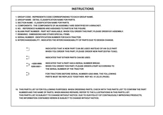
- 1. INSTRUCTIONS 1. GROUP CODE : REPRESENTS CODE CORRESPONDING TO EACH GROUP NAME. 2. GROUP NAME : DETAIL CLASSIFICATION NAME FOR PARTS. 3. SECTION NAME : CLASSIFICATION NAME FOR PARTS. 4. COMPONENTS : THE COMPONENTS OF AN ASSEMBLY ARE IDENTIFIED BY A BRACKET. 5. NO. : REFERENCE NUMBERS ARE ASSIGNED TO PARTS IN THE FIGURE. 6. BLANK PART NUMBER : PART NOT AVAILABLE. WHEN YOU ORDER THIS PART, PLEASE ORDER BY ASSEMBLY. 7. REMARKS : DIMENSIONS AND OTHER SPECIAL ITEMS. 8. SERIAL NUMBER : IDENTIFICATION NUMBER FOR EACH TRACTOR. 9. INTERCHANGEABILITY : INDICATES THE INTERCHANGEABILITY OF PARTS DUE TO DESIGN CHANGE. 10. THIS PARTS LIST IS FOR FOLLOWING PURPOSES. WHEN ORDERING PARTS, CHECK WITH THIS PARTS LIST TO CONFIRM THE PART NUMBER AND THE NAME OF PARTS. WHEN MAKING REPAIRS, REFER TO THE ILLUSTRATIONS IN THIS PARTS LIST. THIS PARTS LIST IS SUBJECT TO CHANGE WITHOUT NOTICE. DUE TO OUR POLICY OF CONTINUOUSLY IMPROVING PRODUCTS, THE INFORMATION CONTAINED HEREIN IS SUBJECT TO CHANGE WITHOUT NOTICE. INDICATES THAT A NEW PART CAN BE USED INSTEAD OF AN OLD PART WHEN YOU ORDER THIS PART, PLEASE ORDER NEW PART(E5700-73382). INDICATES THAT EITHER PARTS CAN BE USED. INDICATES THAT A PART HAS A SERIAL NUMBER BREAK. WHEN YOU ORDER THIS PART, PLEASE ORDER A PART ACCORDING TO THE SERIAL NUMBER OF THE TRACTOR ~4265-9999 5265-0001~ FOR TRACTORS BEFORE SERIAL NUMBER 4265-9999, THE FOLLOWING PARTS MUST BE REPLACE TOGETHER: REF NO. 01,02,03 (PAGE)
- 2. 11. THE SPECIFICATIONS OF EACH MODEL ARE PARTIALLY DIFFERENT FOR THE BELOW TRACTOR WHEN YOU ORDER A SPARE PARTS, YOU HAVE TO ORDER IT ACCODING TO EACH COUNTRY. 12. THE MEANING OF THE MODEL CK20HJ CK20HJ-NL CK20HJ-IT CK20-EU CK20-SP CK20J-AU CK20 CK20-NL CK20J-FR MODEL COUNTRY MODEL COUNTRY MODEL COUNTRY CK20H CK20H-NL CK20J-IT CK20J CK20J-NL CK20HJ-FR (FOR EXAMPLE) CK20FR : MANUAL TRACTOR/FRANCE CK20FR-J : MANUAL JOYSTICK TRACTOR/FRANCE CK20FR-H : HST TRACTOR/FRANCE CK20FR-HJ : HST JOYSTICK TRACTOR/FRANCE JOYSTICK HST COUNTRY MODEL CK20FR - HJ JOYSTICK COUNTRY MODEL CK20FR - J HST COUNTRY MODEL CK20FR - H USA CK20J-EU CK20J-SP CK20HJ-AU CK20H-EU CK20H-SP CK20J-EN CK20HJ-EU CK20HJ-SP CK20HJ-EN EUROPE NETHERLAND SPAIN FRANCE ITALY AUSTRALIA, NEWZEALAND U.K
- 3. TABLE OF CONTENTS E010 CYLINDER BLOCK GROUP ............................................................................................................................................... 8 E020 OIL PAN GROUP ................................................................................................................................................................. 12 E030 CYLINDER HEAD GROUP .................................................................................................................................................. 14 E040 GEAR CASE GROUP.......................................................................................................................................................... 16 E050 MAIN BEARING CASE GROUP ........................................................................................................................................... 20 E060 VALVE, ROCKER ARM GROUP (Old Revision : ~D257-00642)......................................................................................... 22 E060A VALVE, ROCKER ARM GROUP (New Revision : E257-00001~) ....................................................................................... 24 E070 CYLINDER HEAD COVER GROUP (Old Revision : ~D257-00642) ................................................................................... 26 E070A CYLINDER HEAD COVER GROUP (New Revision : E257-00001~).................................................................................. 30 E080 CAMSHAFT GROUP ........................................................................................................................................................... 32 E090 PISTON, CRANKSHAFT GROUP ....................................................................................................................................... 34 E100 FLYWHEEL GROUP............................................................................................................................................................ 38 E110 NOZZLE HOLDER GROUP ................................................................................................................................................ 40 E120 FUEL CAM SHAFT GROUP ................................................................................................................................................ 42 E130 SPEED CONTROL LEVER GROUP .................................................................................................................................. 46 E140 ENGINE STOP LEVER GROUP ......................................................................................................................................... 50 E150 GOVERNOR GROUP ......................................................................................................................................................... 54 E160 WATER PUMP GROUP....................................................................................................................................................... 56 E170 WATER PIPE GROUP......................................................................................................................................................... 58 E180 DYNAMO GROUP ............................................................................................................................................................... 60 E190 MANIFOLD GROUP............................................................................................................................................................. 62 T010 AIRCLEANER GROUP ........................................................................................................................................................ 64 T020 MUFFLER GROUP .............................................................................................................................................................. 66 T030 RADIATOR GROUP ............................................................................................................................................................ 68 T040 WATER TANK GROUP........................................................................................................................................................ 72 T100 CLUTCH GROUP ................................................................................................................................................................ 74 T110 CLUTCH LEVER GROUP ................................................................................................................................................... 76 T120 CLUTCH PEDAL GROUP ................................................................................................................................................... 78 T130 CLUTCH HOUSING 1 GROUP ............................................................................................................................................ 80 - 3 -
- 4. - 4 - T140 CLUTCH HOUSING 2 GROUP ............................................................................................................................................ 82 T150 HST CASE GROUP............................................................................................................................................................. 84 T160 MIDDLE CASE GROUP ...................................................................................................................................................... 86 T170 TRANSMISSION CASE GROUP ......................................................................................................................................... 88 T180 MAIN SHAFT GROUP .......................................................................................................................................................... 90 T190 HST OUTPUT SHAFT GROUP ........................................................................................................................................... 92 T200 COUNTER SHAFT GROUP ................................................................................................................................................ 94 T210 RANGE SHAFT GROUP ..................................................................................................................................................... 98 T220 PTO DRIVING SHAFT GROUP ........................................................................................................................................... 100 T230 PTO SHAFT GROUP .......................................................................................................................................................... 102 T240 MID PTO SHAFT GROUP ................................................................................................................................................... 104 T250 SPIRAL BEVEL GEAR GROUP ........................................................................................................................................... 106 T260 FRONT WHEEL DRIVING GROUP ..................................................................................................................................... 108 T270 MAIN SHIFT FORK GROUP ................................................................................................................................................ 114 T280 MAIN SHIFT LEVER GROUP............................................................................................................................................... 116 T290 RANGE SHIFT FORK GROUP............................................................................................................................................ 118 T300 RANGE SHIFT LEVER GROUP .......................................................................................................................................... 120 T310 HST GROUP........................................................................................................................................................................ 122 T311 HST PART GROUP ............................................................................................................................................................. 124 T320 HST CONTROL 1 GROUP .................................................................................................................................................. 130 T330 HST INNER HYDRAULIC LINE GROUP .............................................................................................................................. 132 T340 PTO & MID PTO FORK GROUP ........................................................................................................................................ 134 T350 PTO & MID PTO LEVER GROUP ....................................................................................................................................... 136 T360 FRONT WHEEL DRIVING FORK GROUP.......................................................................................................................... 138 T370 FRONT WHEEL DRIVING LEVER GROUP ........................................................................................................................ 140 T380 REAR DIFFERENTIAL SYSTEM GROUP ........................................................................................................................... 142 T390 DIFFERENTIAL LOCK FORK GROUP .............................................................................................................................. 144 T400 BRAKE GROUP .................................................................................................................................................................. 146 T401 BRAKE GROUP .................................................................................................................................................................. 150 T405 BRAKE GROUP .................................................................................................................................................................. 154 T410 BRAKE PEDAL GROUP...................................................................................................................................................... 158
- 5. - 5 - T411 BRAKE PEDAL GROUP...................................................................................................................................................... 162 T415 BRAKE PEDAL GROUP...................................................................................................................................................... 166 T420 REAR AXLE GROUP ........................................................................................................................................................... 170 T430 REAR WHEEL GROUP....................................................................................................................................................... 172 T431 REAR WHEEL GROUP....................................................................................................................................................... 174 T435 REAR WHEEL GROUP (Option)......................................................................................................................................... 176 T436 REAR WHEEL GROUP (Option)......................................................................................................................................... 178 T440 FRONT AXLE FRAME GROUP ........................................................................................................................................... 180 T450 FRONT AXLE SUPPORT GROUP...................................................................................................................................... 184 T460 FRONT DIFFERENTIAL GROUP ........................................................................................................................................ 186 T470 BEVEL PINION SHAFT GROUP .......................................................................................................................................... 188 T480 DIFFERENTIAL GEAR SHAFT GROUP .............................................................................................................................. 190 T490 FRONT AXLE CASE GROUP.............................................................................................................................................. 192 T500 FRONT AXLE GROUP ........................................................................................................................................................ 194 T510 STEERING CYLINDER GROUP ......................................................................................................................................... 196 T520 POWER STEERING UNIT GROUP .................................................................................................................................... 198 T530 FRONT AXLE BRACKET GROUP ...................................................................................................................................... 202 T540 PROPELLER SHAFT GROUP ............................................................................................................................................ 204 T550 FRONT WHEEL GROUP .................................................................................................................................................... 206 T551 FRONT WHEEL GROUP .................................................................................................................................................... 208 T555 FRONT WHEEL GROUP (Option) ...................................................................................................................................... 210 T556 FRONT WHEEL GROUP (Option) ...................................................................................................................................... 212 T560-1 HYDRAULIC CYLINDER GROUP ....................................................................................................................................... 214 T561 HYDRAULIC CYLINDER GROUP ....................................................................................................................................... 216 T560-2 HYDRAULIC CYLINDER GROUP ....................................................................................................................................... 218 T570-1 HYDRAULIC CYLINDER BODY GROUP ............................................................................................................................ 220 T571 HYDRAULIC CYLINDER BODY GROUP ............................................................................................................................ 222 T570-2 HYDRAULIC CYLINDER BODY GROUP ............................................................................................................................ 224 T580 HYDRAULIC LIFTARM GROUP .......................................................................................................................................... 226 T590 HYDRAULIC CONTROL SYSTEM 1 GROUP ..................................................................................................................... 228 T600 HYDRAULIC CONTROL SYSTEM 2 GROUP ..................................................................................................................... 230
- 6. - 6 - T610 MAIN DISTRIBUTOR VALVE GROUP ................................................................................................................................. 232 T620 HST CONTROL 2 GROUP .................................................................................................................................................. 236 T630 HST CONTROL 3 GROUP .................................................................................................................................................. 240 T640 GEAR PUMP GROUP ......................................................................................................................................................... 244 T650 SUCTION PIPE GROUP ..................................................................................................................................................... 248 T660 OIL FILLER PIPE GROUP ................................................................................................................................................... 252 T670 FLOW CONTROL VALVE GROUP ..................................................................................................................................... 254 T680 HST EXTERNAL HYDRAULIC LINE GROUP ...................................................................................................................... 258 T690 JOYSTICK GROUP ............................................................................................................................................................. 262 T691 JOYSTICK (1) ...................................................................................................................................................................... 266 T700 EXTERNAL HYDRAULIC VALVE GROUP (Option) ............................................................................................................. 270 T701 DOUBLE ACTING VALVE GROUP (Option) ........................................................................................................................ 272 T710 POSITION CONTROL VALVE GROUP ............................................................................................................................... 276 T720 DOWN SPEED CONTROL GROUP .................................................................................................................................. 278 T730 THREE POINT LINK SYSTEM GROUP .............................................................................................................................. 280 T740 DRAWBAR GROUP ............................................................................................................................................................ 284 T750 BONNET 1 GROUP............................................................................................................................................................. 286 T760 BONNET 2 GROUP............................................................................................................................................................. 288 T770 BONNET 3 GROUP............................................................................................................................................................. 292 T780 FRAME GROUP .................................................................................................................................................................. 294 T790 FUEL TANK GROUP............................................................................................................................................................ 298 T800 ACCELERATOR GROUP ................................................................................................................................................... 302 T810 INSTRUMENT COVER GROUP.......................................................................................................................................... 304 T815 INSTRUMENT COVER GROUP.......................................................................................................................................... 306 T820 FENDER GROUP ................................................................................................................................................................ 308 T825 FENDER GROUP ................................................................................................................................................................ 314 T830 SEAT FLOOR GROUP........................................................................................................................................................ 320 T831 SEAT FLOOR GROUP........................................................................................................................................................ 322 T840 STEP GROUP ..................................................................................................................................................................... 324 T850 SEAT GROUP...................................................................................................................................................................... 326 T850A SEAT GROUP...................................................................................................................................................................... 328
- 7. - 7 - T855 SEAT GROUP...................................................................................................................................................................... 330 T856 SEAT GROUP...................................................................................................................................................................... 332 T860 BATTERY GROUP .............................................................................................................................................................. 334 T870 ELECTRICAL SYSTEM 1 GROUP ...................................................................................................................................... 336 T875 ELECTRICAL SYSTEM 1 GROUP ...................................................................................................................................... 338 T880 ELECTRICAL SYSTEM 2 GROUP ...................................................................................................................................... 340 T890 ELECTRICAL SYSTEM 3 GROUP ...................................................................................................................................... 344 T900 LIGHT GROUP..................................................................................................................................................................... 346 T905 LIGHT GROUP..................................................................................................................................................................... 348 T910 LABEL GROUP .................................................................................................................................................................... 352 T915 LABEL GROUP .................................................................................................................................................................... 356 T916 LABEL GROUP .................................................................................................................................................................... 364 T920 ROPS GROUP (Option) ...................................................................................................................................................... 368 T921 ROPS GROUP (Option) ...................................................................................................................................................... 370 T925 ROPS GROUP (Option) ...................................................................................................................................................... 372 T928 ROPS GROUP (Option) ...................................................................................................................................................... 374 T930 TOWING HOOK GROUP (Option) ...................................................................................................................................... 376 T931 TOWING HOOK GROUP (Option) ...................................................................................................................................... 378 T940-1 FRONT WEIGHT GROUP (Option) ..................................................................................................................................... 380 T940-2 REAR WHEEL WEIGHT GROUP (Option) ......................................................................................................................... 382 T960 7 PIN SOCKET GROUP (Option)........................................................................................................................................ 384 T970 BACKMIRROR GROUP ...................................................................................................................................................... 386 T971 BACKMIRROR GROUP ...................................................................................................................................................... 388 T975 BACKMIRROR GROUP ...................................................................................................................................................... 390 T980 PARKING BRAKE GROUP .................................................................................................................................................. 392 T990 WORKING LIGHT GROUP (Option) .................................................................................................................................... 396 T1020 SUNSHADE GROUP (Option) ............................................................................................................................................. 398 INDEX1 ............................................................................................................................................................................................. 401 INDEX2 ............................................................................................................................................................................................. 421 INDEX3 ............................................................................................................................................................................................. 427
- 8. - 8 - E010 CYLINDER BLOCK GROUP
- 9. - 9 - PART. NO DESCRIPTION REMARK I.C REF. NO Q’TY CK20HJ-EU CK20H-EU CK20J-EU CK20-EU CK20HJ CK20H CK20J CK20 CYLINDER BLOCK ASS’Y CYLINDER BLOCK ASS’Y CYLINDER BLOCK ASS’Y CYLINDER BLOCK ASS’Y BLOCK, CYLINDER LINER, CYLINDER LINER, CYLINDER PLUG PLUG PLUG PLUG PLUG, EXPANSION PLUG, EXPANSION PLUG, EXPANSION PLUG, SEALING PIN, STRAIGHT PIN, STRAIGHT PIN PIN PIN GASKET, COVER COVER, WATER BOLT JOINT, DRAIN HOSE GASKET, OIL PUMP E5753-A0018 E5753-A0019 E5753-A0200 E5753-A0201 E5700-02313 E5700-02314 15521-9602-2 E5900-96021 15521-9603-2 E5900-96031 06311-75015 06311-75040 15321-9626-3 15221-0349-3 05012-00609 05012-00814 E5205-33961 15221-3365-1 E5753-33811 15261-7392-1 E5205-73911 01023-50618 E5205-73173 E5700-35152 01 01 01 01 02 03 03 04 04 05 05 06 07 08 09 10 11 12 13 14 15 16 17 18 19 1 1 1 1 1 1 1 9 9 1 1 3 1 5 1 2 2 2 1 1 1 1 2 1 1 1 1 1 1 1 1 1 9 9 1 1 3 1 5 1 2 2 2 1 1 1 1 2 1 1 1 1 1 1 1 1 1 9 9 1 1 3 1 5 1 2 2 2 1 1 1 1 2 1 1 1 1 1 1 1 1 1 9 9 1 1 3 1 5 1 2 2 2 1 1 1 1 2 1 1 1 1 1 1 1 9 9 1 1 3 1 5 1 2 2 2 1 1 1 1 2 1 1 1 1 1 1 1 9 9 1 1 3 1 5 1 2 2 2 1 1 1 1 2 1 1 1 1 1 1 1 9 9 1 1 3 1 5 1 2 2 2 1 1 1 1 2 1 1 1 1 1 1 1 9 9 1 1 3 1 5 1 2 2 2 1 1 1 1 2 1 1 Order By 1
- 10. - 10 - E010 CYLINDER BLOCK GROUP
- 11. - 11 - PART. NO DESCRIPTION REMARK I.C REF. NO Q’TY CK20HJ-EU CK20H-EU CK20J-EU CK20-EU CK20HJ CK20H CK20J CK20 OIL PUMP ASS’Y BOLT KEY, FEATHER GEAR, OIL PUMP DRIVING NUT, FLANGE SWITCH, OIL O-RING E5700-35012 E5205-91021 05712-00408 E5700-35662 E5753-35681 E5500-39013 E5500-33702 20 21 22 23 24 25 26 1 4 1 1 1 1 1 3257-00149~ 1 4 1 1 1 1 1 3257-00149~ 1 4 1 1 1 1 1 3257-00149~ 1 4 1 1 1 1 1 3257-00149~ 1 4 1 1 1 1 1 3257-00149~ 1 4 1 1 1 1 1 3257-00149~ 1 4 1 1 1 1 1 3257-00149~ 1 4 1 1 1 1 1 3257-00149~
- 12. - 12 - E020 OIL PAN GROUP
- 13. - 13 - PART. NO DESCRIPTION REMARK I.C REF. NO Q’TY CK20HJ-EU CK20H-EU CK20J-EU CK20-EU CK20HJ CK20H CK20J CK20 OIL PAN ASS’Y GASKET, OIL PAN BOLT PLUG, DRAIN WASHER, SEAL FILTER 1, OIL BOLT, FLANGE O-RING GAUGE, OIL GAUGE, OIL GUIDE, OIL GAUGE GUIDE, OIL GAUGE OIL GAUGE GUIDE PACKING E5700-A0072 E5700-01623 E5700-91094 15221-3375-2 04717-01200 E5700-32112 01654-50820 04811-00140 E5752-36411 E5752-36412 E5752-35691 E5752-35692 E5752-36422 E7310-36431 01 02 03 04 05 06 07 08 09 09 10 10 11 12 1 1 18 1 1 1 1 1 1 1 1 1 1 1 1 1 18 1 1 1 1 1 1 1 1 1 1 1 1 1 18 1 1 1 1 1 1 1 1 1 1 1 1 1 18 1 1 1 1 1 1 1 1 1 1 1 1 1 18 1 1 1 1 1 1 1 1 1 1 1 1 1 18 1 1 1 1 1 1 1 1 1 1 1 1 1 18 1 1 1 1 1 1 1 1 1 1 1 1 1 18 1 1 1 1 1 1 1 1 1 1 1
- 14. - 14 - E030 CYLINDER HEAD GROUP
- 15. Thank you very much for your reading. Please Click Here. Then Get COMPLETE MANUAL. NO WAITING NOTE: If there is no response to click on the link above, please download the PDF document first and then click on it.
- 16. - 15 - PART. NO DESCRIPTION REMARK I.C REF. NO Q’TY CK20HJ-EU CK20H-EU CK20J-EU CK20-EU CK20HJ CK20H CK20J CK20 CYLINDER HEAD ASS’Y CYLINDER HEAD ASS’Y CYLINDER HEAD ASS’Y HEAD, CYLINDER PLUG, SEALING PLUG, SEALING PLUG PLUG GUIDE, INLET VALVE GUIDE, EXHAUST VALVE BOLT, HEAD CHAMBER, COMBUSTION GASKET, CYLINDER HEAD GASKET, CYLINDER HEAD SWITCH, THERMOMETER HOOK, ENGINE HOOK, ENGINE STUD BOLT WASHER, SPRING NUT E5753-03045 E5753-03046 E5753-03047 E5205-03371 15321-9626-3 15521-9602-2 E5900-96021 E5205-13542 E5205-13562 E5205-03452 E5700-03144 E5753-03312 E5753-03313 E5205-32832 15221-0175-1 E6305-01751 01513-50822 01123-50816 04512-50080 02156-50080 01 01 01 02 03 04 05 05 06 07 08 09 10 10 11 12 13 14 15 16 17 1 1 ~D257-00642 1 E257-00001~ 1 5 1 2 2 3 3 14 3 1 ~3257-00148 1 3257-00149~ 1 1 1 1 1 1 1 1 1 ~D257-00642 1 E257-00001~ 1 5 1 2 2 3 3 14 3 1 ~3257-00148 1 3257-00149~ 1 1 1 1 1 1 1 1 1 ~D257-00642 1 E257-00001~ 1 5 1 2 2 3 3 14 3 1 ~3257-00148 1 3257-00149~ 1 1 1 1 1 1 1 1 1 ~D257-00642 1 E257-00001~ 1 5 1 2 2 3 3 14 3 1 ~3257-00148 1 3257-00149~ 1 1 1 1 1 1 1 1 1 ~D257-00642 1 E257-00001~ 1 5 1 2 2 3 3 14 3 1 ~3257-00148 1 3257-00149~ 1 1 1 1 1 1 1 1 1 ~D257-00642 1 E257-00001~ 1 5 1 2 2 3 3 14 3 1 ~3257-00148 1 3257-00149~ 1 1 1 1 1 1 1 1 1 ~D257-00642 1 E257-00001~ 1 5 1 2 2 3 3 14 3 1 ~3257-00148 1 3257-00149~ 1 1 1 1 1 1 1 1 1 ~D257-00642 1 E257-00001~ 1 5 1 2 2 3 3 14 3 1 ~3257-00148 1 3257-00149~ 1 1 1 1 1 1 1 Order By 1
- 17. - 16 - E040 GEAR CASE GROUP
- 18. - 17 - PART. NO DESCRIPTION REMARK I.C REF. NO Q’TY CK20HJ-EU CK20H-EU CK20J-EU CK20-EU CK20HJ CK20H CK20J CK20 GEAR CASE ASS’Y GEAR CASE ASS’Y GEAR CASE ASS’Y GEAR CASE ASS’Y CASE, GEAR PLUG PLUG PIN, START SPRING RELIEF VALVE ASS’Y BODY, RELIEF VALVE SPRING BALL, STEEL SEAT, VALVE O-RING O-RING STUD SUPPORT, OIL FILTER SUPPORT, OIL FILTER SUPPORT, OIL FILTER PLUG PLUG WASHER, SPRING NUT BOLT TUBE, JOINT E5744-A0013 E5744-A0014 E5744-A0015 E5744-A0017 15521-9603-2 E5900-96031 15221-5628-2 E5205-36071 E5205-36911 15241-3695-2 07715-03213 E5700-36932 04810-00150 04811-05140 15221-8821-1 E5205-32312 E5700-32312 E5700-32313 15521-9603-2 E5900-96031 04512-50060 02056-50060 01023-50630 E5205-32291 01 01 01 01 02 03 03 04 05 06 07 08 09 10 11 12 13 13 13 14 14 15 16 17 18 1 1 ~3257-02212 1 3257-02213~ 1 1 2 2 1 1 1 1 1 1 1 2 1 1 ~3257-02212 1 3257-02213~ 1 2 2 2 2 2 1 1 1 ~3257-02212 1 3257-02213~ 1 1 2 2 1 1 1 1 1 1 1 2 1 1 ~3257-02212 1 3257-02213~ 1 2 2 2 2 2 1 1 1 ~3257-02212 1 3257-02213~ 1 1 2 2 1 1 1 1 1 1 1 2 1 1 ~3257-02212 1 3257-02213~ 1 2 2 2 2 2 1 1 1 ~3257-02212 1 3257-02213~ 1 1 2 2 1 1 1 1 1 1 1 2 1 1 ~3257-02212 1 3257-02213~ 1 2 2 2 2 2 1 1 1 ~3257-02212 1 3257-02213~ 1 1 2 2 1 1 1 1 1 1 1 2 1 1 ~3257-02212 1 3257-02213~ 1 2 2 2 2 2 1 1 1 ~3257-02212 1 3257-02213~ 1 1 2 2 1 1 1 1 1 1 1 2 1 1 ~3257-02212 1 3257-02213~ 1 2 2 2 2 2 1 1 1 ~3257-02212 1 3257-02213~ 1 1 2 2 1 1 1 1 1 1 1 2 1 1 ~3257-02212 1 3257-02213~ 1 2 2 2 2 2 1 1 1 ~3257-02212 1 3257-02213~ 1 1 2 2 1 1 1 1 1 1 1 2 1 1 ~3257-02212 1 3257-02213~ 1 2 2 2 2 2 1 Order By 1
- 19. - 18 - E040 GEAR CASE GROUP
- 20. - 19 - PART. NO DESCRIPTION REMARK I.C REF. NO Q’TY CK20HJ-EU CK20H-EU CK20J-EU CK20-EU CK20HJ CK20H CK20J CK20 STUD GASKET, HOUR METER HOUR METER ASS’ Y WASHER, SPRING NUT SEAL, OIL O-RING GASKET, GEAR CASE CLAMP, TUBE BOLT BOLT BOLT BOLT FILTER, OIL BOLT 15221-8821-1 15221-8813-1 E5205-58812 04512-50060 02056-50060 09550-00008 04811-06130 E5700-04134 E5205-73142 01023-50660 01023-50665 01023-50670 01023-50675 E5205-32091 E5752-91031 19 20 21 22 23 24 25 26 27 28 29 30 31 32 33 4 1 1 4 4 1 3 1 1 5 4 2 1 1 2 4 1 1 4 4 1 3 1 1 5 4 2 1 1 2 4 1 1 4 4 1 3 1 1 5 4 2 1 1 2 4 1 1 4 4 1 3 1 1 5 4 2 1 1 2 4 1 1 4 4 1 3 1 1 5 4 2 1 1 2 4 1 1 4 4 1 3 1 1 5 4 2 1 1 2 4 1 1 4 4 1 3 1 1 5 4 2 1 1 2 4 1 1 4 4 1 3 1 1 5 4 2 1 1 2
- 21. - 20 - E050 MAIN BEARING CASE GROUP