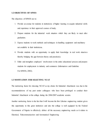
SlideShare a Scribd company logo
1 of 63
1
CHAPTER ONE
GENERAL INTRODUCTION
1.1 PREAMBLE
The students’ Industrial Work Experience Scheme (SIWES) is a skill Training programme
designed to expose and prepare students of Agriculture, Engineering, Technology, Environmental,
Science, Medical Sciences and pure and applied sciences for the Industrial work situation which
they are likely to meet after graduation.
The students’ industrial work experience scheme (SIWES) is the acceptable skills training
programme which forms part of the minimum academic standards in the various degree
programmes for Nigerian universities. It is an effort to bridge the gap existing between theory and
practical of science and technology and other professional educational programmes in the Nigerian
tertiary institution.
SIWES was established by ITF (Industrial Training Fund) in 1973 to solve the problem of lack of
adequate practical skills preparatory for employment in industries by Nigerian graduates of tertiary
institutions.
The Scheme exposes students to industry based skills necessary for a smooth transition from the
classroom to the world of work. It affords students of tertiary institutions the opportunity of being
familiarized and exposed to the needed experience in handling machinery and equipment
Which are usually not available in the educational institutions.
2
1.2 OBJECTIVES OF SIWES
The objectives of SIWES are to:
1. Provide an avenue for students in institutions of higher learning to acquire industrial skills
and experience in their approved courses of study.
2. Prepare students for the industrial work situation which they are likely to meet after
graduation.
3. Expose students to work methods and techniques in handling equipment and machinery
not available in their institutions.
4. Provide students with an opportunity to apply their knowledge in real work situation
thereby bridging the gap between theory and practice(s).
5. Enlist and strengthen employers’ involvement in the entire educational process and prepare
students for employment in industry and commerce (Information and Guideline
For SIWES, 2002).
1.3 MOTIVATION FOR SELECTING NCAT
The motivating factor for choosing NCAT as my choice for Industrial Attachment was due to the
recommendations of my past senior colleagues who have been privileged to conduct their
Industrial Attachment at the college during the 2006/2007 academic session.
Another motivating factor is the fact that I will become the first Liberian engineering student given
this opportunity in this great institution and also the college is well equipped by the Federal
Government of Nigeria to effectively deliver all the necessary engineering needs as it relates to
Electrical, Telecommunication and Aeronautical Engineering.
3
The desire to gain practical Electrical experience was also a driving force that motivated my
interest to apply for my SIWES training at NCAT, Zaria.
1.4 TRAINING METHODOLOGY IN SIWES PLACE
In the Department were I was posted in NCAT, an enormous amount of physical and intellectual
strength is required because majority of the jobs are done within the laboratory and then on site.
Almost all the installation processes involves a great deal of cabling; that is running cable through
trunkings and PVC pipes. Repairs and installation of power inverter, air condition system, diesel
engine, telephone lines and airfield ground lighting system (AGLs).
The basic tools often used are the fishing tapes, Screwdrivers, Installation tapes, Tester,
Multimeter, Pliers, Cutter, Chisel, Mallet, Drilling machines, Screws, Cables, Connectors to
mention a few.
At the site, trainees are allowed to be fully involved in sharing ideas and solving practical problems
as they arise. Each trainee is encouraged to come to work with the right tools to facilitate practical
understanding and experience acquired.
1.5 REPORT OUTLINE
This Technical report is compiled and documented from my SIWES experience at the Nigerian
College of Aviation Technology (NCAT), Zaria, from 13th April, 2013 to 16th September, 2013.
Chapter one contains introduction to the Student Industrial Work Experience Scheme (SIWES). It
defines the scheme and explains briefly the aims and objectives of the scheme to the benefit of
students in tertiary institutions.
4
Chapter Two contains the theoretical background of my SIWES Area. A brief historical
background of the Nigerian College of Aviation Technology (NCAT), Zaria is discussed and the
various departments of the school and an organogram of the Works Department were the Industrial
attachment was done.
Chapter Three explains extensively about the training and experiences gained by me during the
Industrial attachment at NCAT.
Chapter Four contains the experience gained from the training at The Nigerian College of Aviation
Technology (NCAT), Zaria, and also its application in my future career.
Chapter Five contains the conclusion and general appraisal of the programme which includes the
Limitations, Difficulties and Suggestions to future SIWES students.
5
CHAPTER TWO
THEORETICAL BACKGROUND OF THE SELECTED SIWES AREA
2.1 INTRODUCTION
The Nigerian College of Aviation Technology (formerly known as the Nigerian Civil Aviation
Training Centre) Zaria was established in 1964. It is a unique civil aviation training institution
due to it organizational structure, the College consist of the Office of the Rector/Chief Executive
is run by nine units, five schools and four service departments as follows:-
A. UNITS
1. Planning, Research and Statistics Unit;
2. Public Relation Unit;
3. Information and Communication Technology (ICT) Unit;
4. Security Unit;
5. Legal Unit;
6. Aero-medical Unit;
7. Commercial Service Directorate;
8. Audit Unit;
9. Quality Assurance Unit.
B. SCHOOLS
1. Aircraft Maintenance Engineering School (AME);
2. Aeronautical Telecommunication School (ATE);
6
3. Air Traffic Service/Communication School (ATS/COM);
4. Aviation Management School;
5. Flying School.
C. SERVICE DEPARTMENTS
1. Registry Department;
2. Bursary Department;
3. Works and Technical Service;
4. Flight Maintenance Department.
2.2 BRIEF HISTORYOF THE NIGERIAN COLLEGE OF AVIATION TECHNOLOGY(NCAT)
The Nigerian College of Aviation Technology, Zaria, (formerly known as Nigerian Civil Aviation
Training Center) was set up by Act. No 31 of 1964 (as amended), to conduct:
► Civil Aviation courses for use in flight training or airport operations & management as may be
prescribed from time to time.
► Training of approved persons in the installation, maintenance and operation, as the case may
be, of technical equipment, the use of which is calculated or likely to increase the margin of
operational safety of civil aircrafts.
► Training on equipment’s and necessary facilities for technical research or normal use.
(www.ncat.gov.ng)
The idea of a center for aviation training in Nigeria was first mooted at an International Forum, the
12th International Civil Aviation Organization (ICAO) Assembly, held in San Diego, California,
7
USA, in 1959. The Federal Government of Nigeria then formally requested the United Nations
Development Programme to appoint an expert to assess the actual requirements for the setting up
of a Civil Aviation Training Center in Nigeria. The report of the project was approved in 1963,
and a bill establishing a Center for Civil Aviation Training at Zaria, Nigeria, was passed by the
Federal Legislature on 29th September, 1964, and signed into law on October 23, 1964.
(www.ncat.gov.ng)
The Center was established as a joint programme between the Federal Government of Nigeria
(FGN), the United Nations Development Programme (UNDP), and the International Civil Aviation
Organization (ICAO). This joint programme of assistance from the UNDP and ICAO came to an
end on 31st December, 1974 and the Federal Government of Nigeria assumed full responsibility
for the continued management and operation of the College.
In 1977, the Board of Governors of the College recommended to the Federal Government a change
of name from NIGERIAN CIVIL AVIATION TRAINING CENTER (NCATC) to NIGERIAN
COLLEGE OF AVIATION TECHNOLOGY (NCAT), in anticipation of expansion of training
and related activities. Official approval did not come until 1986, when the Government issued a
White Paper on the “Report of the Fact-Finding Panel into the Activities of the Civil Aviation
Department in the Federal Ministry of Aviation”. The change of name was reflected in Decree No.
41 of 1990. (www.ncat.gov.ng)
2.2.1 LOCATION
The College is located in Palladan, a suburb of Zaria in Kaduna State, which is in the North -
Western part of Nigeria.
8
Over the years, Palladan has evolved from a small colonial farming settlement to a large
community. Zaria is a large city with a cosmopolitan population of about 1,500,000. Areas of
economic importance include farming and education, hence it can easily be referred to as an
“educational town,” being home to various academic institutions like the prestigious Ahmadu
Bello University (ABU), Federal College of Education (FCE), Nigerian Institute of Transport
Technology (NITT), National
Research Institute of Chemical Technology (NARICT) and Chemical and Leather Research
Technology (CHELTECH).
Zaria is characterized by a tropical, continental climate with an extensive dry season (October –
May). During this period, a cool is usually experienced due to the North-Eastern winds (the
Harmattan) which controls the tropical continental air mass coming in from the Sahara. This
weather prevails over most parts of the country. Temperatures get as low as 10oC at night and a
high of 40oC is often recorded in afternoons. In March and April, hot but dry weather is
encountered, trailed by a sweeping-in of the tropical maritime air mass from the Atlantic Ocean
which displaces the North-Eastern winds. Temperature recorded during this period ranges between
38oC – 42oC. The moisture laden South-Western monsoon winds then take over, bringing in heavy
rainfall between May – September/October. (www.ncat.gov.ng)
2.2.2 OBJECTIVES
The primary objectives of the College are:
• To conduct civil aviation training for use in flight training or airport operations.
9
• To train approved persons in installation, maintenance and operation of technical
equipment, the use of which is calculated or likely to increase the margin of operational
safety of civil aircraft services.
• To train approved personnel on equipment and necessary facilities for technical research
or normal use.
Training activities at the College reached the peak between the 80’s and 90’s. This was due to the
provision of more training facilities like the F28 Simulator, a large fleet of trainer aircraft,
construction of a bigger (the 3rd) hangar and classrooms, resulting into an increase in the number
of instructional personnel, professionals and students. At inception, the College ran some four
standard courses in Piloting, Air Traffic Services, Aircraft Maintenance Engineering and
Aeronautical Telecommunications Engineering. Today, it runs over 65 standard and abridged
courses. The first set of graduates from the College was 22 in number. By the year ending 1999,
students graduating from the College had totaled 4,747 and to date, well over 6,800 graduates have
been produced in various fields of aviation. (www.ncat.gov.ng)
2.3 AERONAUTICAL TELECOMMUNICATION ENGINEERING SCHOOL
The School of Aeronautical Telecommunication trains students Engineers/Technologists on the
installation and Maintenance of communication, Navigation aids and Radar surveillance systems
The objectives of Aeronautical Telecommunication Engineering (ATE) School are:-
 Installing of lighting system on the approach end of an airport runway.
 Help pilot to ease his taking off and landing safely.
 Repairs of damage or installing of communication equipment in the college.
 Repairs of damage systems and installation of software in computers
10
 Generation of light within the college and college quarters
The school is also involved of the training of student Engineers in the maintenance and installation
of communication, computer package and navigation.
This school has graduated a total number of 1,309 students since its inception and has five (5)
departments which are;
i. Power System and Maintenance Department (PSM);
ii. Navigational-Aids Department (NAVAIDS);
iii. Radar Maintenance Department (RAD);
iv. Communication Equipment and Maintenance Department (CEM);
v. General Electronics and Computer Studies Department (GEC);
This School is the school focus on a specific line activities which is Project handing. This Include
air condition installation (AC), maintaining computer systems, repairs of communication
equipment, airfield ground lighting system and diesel engine generators. It is actually responsible
for the development and moving the college forward to ensure that its vision and mission are
accomplished. Since the establishment of the school, it has been headed by several heads of school.
The present head of school Engr. J. O. Ikhigbonoaremen although staff are being transfer within
departments. The school comprises of experienced and learned staff who are mostly Electrical
Engineers and Computer Scientists. See Fig 1.1 below:
Fig 1.1 ATE School Building
11
2.3.1 ORGANOGRAM OF AERONAUTICAL TELECOMMUNICATION ENGINEERING
DEPARTMENT IN NCAT
The block diagram in fig. 2.1 shows the Organogram of the A.T.E Department of the Nigerian
College of Aviation Technology (NCAT), Zaria.
12
From the organogram, it can be seen that the A.T.E department is further subdivided into sections
with different work function but all under the supervision of the Head of A.T. E. The function of
each section is briefly highlighted.
2.3.2 POWER SYSTEM MAINTENANCE DEPARTMENT (PSM)
This department deals with the construction and maintenance of devices such as light system,
generator, and air conditioners (AC) inverters, air field ground lighting system (AGLS. They
majorly maintain Electrical installations, wiring, maintenance and repairs of Air Conditioners,
diesel engine and inverters. Furthermore they handles most of the management and supervision of
engineering projects carried out in the college. A team of professionals comprising of Electrical
Engineers, Architect, Civil Engineers and Quantity Surveyors are mandated with the task of
ensuring that all projects awarded by the college to contractors, are completed in conformation
with standards up in place in the various engineering fields.
2.3.3 COMMUNICATION EQUIPMENT MAINTENANCE LABORATORY (CEM)
The CEM laboratory deals with fiber optic, very small aperture terminal (VSAT), communication
and repairs of communication equipment (telephone lines) in the college.
2.3.4 GENERAL ELECTRONICS AND COMPUTER LABORATORY (GEC)
This department deals with electronic and computers which aids in communication. The
department helps in training student in circuit analyzing, computer packages and control
engineering.
13
2.3.5 NAVIGATION-AIDS DEPARTMENT (NAVAIDS)
This department mostly deals with the safety of life and property, they achieve this by working
with few electronic device including, instrument landing system (ILS) 420, which is highly
resistant to several weather condition. Like the ANTENNA, TRANSCEIVER, TRANSMITTER,
GPS, DME, VOR, etc.
2.3.6 RADER MAINTENANCE DEPARTMENT (RAD)
This department work with electronic device just like the above department, which protect the air
space with help of display equipment, including the air traffic system department.
14
CHAPTER THREE
DETAILS OF THE TRAINING UNDERGONE IN THE SIWES PLACE
3.1 INTRODUCTION
At the ATE school where I was posted has five department and these department functions
according to its structured, the school offers training of personnel in the installation and
maintenance of communication, NAV-Aids and surveillance system for the civil aviation industry.
The PSM and CEM department, is where we carry out most of our jobs for the college (NCAT).
See (2.3.1, 2.3.2) in chapter two. Because of my discipline (Electrical and Computer Engineering)
We were posted to the others department see: (2.3.4, 2.3.5, 2.3.6) in chapter two. So that we can
have some basic knowledge about the above department.
i. On a daily basis, the ATE department handles a lot of new Jobs and repairs from the HOD
office, flying school, staff residence and flight hangers. These new Jobs and repairs are
analyzed in the early morning meetings usually held by 8:30am, Monday to Friday. By
9:00am, the staff and Industrial trainees are assigned to different jobs.
ii. Electrical maintenance work carried out include: installation of electrical fittings like Lamp
Holders, Fluorescent fittings, 13A and 15A sockets, Ceiling rose, installation of 2way one gang
and 2way 2 gang switch installation, installation of Earth Leakage Circuit Breakers, Distribution
Box, Cut-out Fuses, repair and maintenance of Air conditioners, and repair of Ceiling fans.
iii. The CEM department handles a lot of Job cards from the Registry office, flying school,
staff residence and flight hangers. These job cards are analyzed in the early morning
meetings usually held by 8:30am, Monday to Friday. By 9:00am, the staff and Industrial
trainees are assigned to different jobs.
15
3.1.1 ELECTRICITY
Electricity is far too dangerous to handle if you have not been trained how to carryout electrical
installation or repair work in safe manner. A fault could occur if the wrong size and type of breaker
and/or the wrong size and type of cable are used for the job. The user of the equipment could be
electrocuted if a wrong connection in the wiring is done at the wrong place.
At Nigerian College of Aviation Technology (NCAT), I was taught how to practically implement
safety procedures when carrying out electrical installation or repair work. We handled general
maintenance of Hostels, Office Annex, Hangers, Aircraft maintenance school and Residential
homes of the Aviation staff in the college and other sites outside the college area.
3.2 DISTRIBUTION OF ELECTRICITY TO CONSUMER HOMES/LABORATORY
The distribution of Electricity to consumers’ lines has its source at the generating plant which host
a turbine. Transformers at substations boost the power transmitted while transmission line carry
this electricity to the consumer transformer that step down this voltages to consumer voltages. At
the Distribution line, 415v 3phase lines distribute the electricity from the transformer to Industries
at 415v, commercial and residential load center at 240v. After the domestic electrical installation,
including domestic wiring installation, power changeover, 3phase start/delta contactor, with 220v
to 110v step-down transformer and also we carry out few maintenance at the Airfield ground
lighting simulator (AGL) ATE. See: Fig.3.1, Fig.3.1A, and Fig.3.1B up to Fig.3.1H, for the
practical view in full.
The Diagram in Fig. 3.1 shows the Distribution line and how they are distributed to various
consumer locations.
16
Fig. 3.1 Distribution of Electricity to consumer homes/Laboratory
Fig. 3.1A. AGL circuit fault solution Fig. 3.1B. picture of AGL
Fig. 3.1C. Domestic wiring installation Fig. 3.1D. Domestic wiring installation testing
415V
415V
415V 240V
V240
Red - Line 1
Blue - Line 3
Neutral
Yellow - Line 2
HOUSE1
HOUSE2
INDUSTRY
3PHASE
MACHINES
17
Fig. 3.1E. Final work testing Fig. 3.1F. Changeover fitting
Fig. 3.1G. Start/delta contactor inspection Fig. 3.1H. Start/delta contactor
3.3 INSTALLATION OF A CEILING ROSE
A Ceiling rose serves as a connector that connects several Lighting points and switches together in
the correct cable arrangement to effectively distribute power supply to other parts of the wiring
circuit.
The diagram in figure 3.2 shows the cable connections in a ceiling rose as I was taught during my
industrial training with NCAT.
18
Fig. 3.2A. Cable connections in a Ceiling Rose.
3.4 INSTALLATION OF 2-WAY SWITCH ON A POINT OF LIGHT
A 2-way switch installation on a point of light is simply a method of wiring that has to do with
having 2 switches controlling one point of light. This type of wiring is mostly applicable in
corridors of houses and sometimes in the bedroom, were one switch is at the entrance of the door
and the other at the side of the bed.
A typical explanation of a 2-way connection can be seen in the following diagrams in figure 3.3
and 3.4.
Fig. 3.3 One-gang Two-way Switch
19
.
Fig 3.4 Two-gang Two-way switch
3.5 AN ELECTRICAL JUNCTION BOX IN SURFACE WIRING
An electrical junction box is a very important part of an electrical wiring system, especially in
surface wiring. Without a junction box, one simply cannot have many different types of electrical
outlets, switches, or data hook ups in a room. The electrical junction box is the place where all the
wires in a room, or wiring area, are joined together and fed by the main breaker. Junction boxes
can then be called a control room of sorts. They send power from the main breaker to the other
parts of the room. These junction boxes are usually hid behind the drywall, or paneling as they
serve no aesthetic function.
3.5.1 INSTALLING THE JUNCTION BOX
• It is advisable to get started in a safe manner by turning-off the power to the circuit that
will be worked upon. Turning-off the power supply could be achieved in many ways. This
could mean turning-off the circuit breaker that was previously installed or simply
unplugging a fuse.
20
• Using a power tester, ensure that there is no active electrical connection in the circuit
• If there are any wire splices that are hanging near the circuit, place it in a protective,
insulated box.
• Pull the two wires in the junction box to the back, after removing the knockouts from the
junction box. This helps to allow the wires to be pulled back more comprehensively.
• Install the cable connectors in the voids created due to the knockouts being emptied.
• Using the pliers, tighten the locknuts around the connectors. The wire should be able to
slide within the connectors without too much pushing.
• Once the wires have slid through, tighten them with the screwdriver.
• For securing this connection, push two screws through the holes present in the back of the
junction box to secure it upon the wooden joist. Fasteners can also be used to for securely
mounting the box.
• Using the linesman pliers, twist the wires together. Join the wires by color coordination,
i.e. black with black, white with white and the bare copper wire to its counterpart and twist
the wires, firmly and evenly.
• Use the wire nuts to cover the wire connections. It is advisable to use the green-colored
wire nuts for the bare copper or the ground wire as it conventionally symbolizes a ground
connection.
• Now that the wires have been covered, it is time to cover with a blank cover plate.
21
Check and tuck the wires into their place and cover the junction box with its cover plate.
Fig. 3.5 wiring connections in an Electrical Junction Box
3.5.2 MATERIALS NEEDED FOR INSTALLING A JUNCTION BOX
• Junction box (including the cover plate/box cover)
• Linesman pliers
• Standard, household pliers
• Hammer
• Screwdriver
• Wiring fasteners
• Cable connectors
• Wire nuts
• Power tester
3.6 ELECTRICAL DISTRIBUTION BOARD
An Electrical distribution board (or panel board) is a component of an electricity supply system
which divides an electrical power feed into subsidiary circuits, while providing a protective fuse
or circuit breaker for each circuit, in a common enclosure.
There are two types of Distribution board which are: Single phase distribution board and 3-Phase
22
Distribution boards. Figure 3.6 and 3.7 shows a diagrammatic view of the two types of Distribution
Board currently available in the market.
Fig. 3.6. 3-phase distribution Board Fig. 3.7 Single phase distribution Board
The connections in the Distribution Board will look like this:
Fig. 3.8A. Wiring Connections in the Distribution Board
3.7 EARTH LEAKAGE CIRCUIT BREAKERS (ELCBs)
The earth leakage circuit breakers or commonly called ELCBs are located inside the home
electrical panel or distribution board. This component of the home electrical installation is designed
to detect any leakage of electrical current.
Fig 3.8B. Wiring Connections
in the Distribution Board
23
This so-called leakage current occurs when there are some defects in the performance of some
parts of the installation. These defects can be caused by faulty parts or by injuries to the insulation
of the wiring, cables, electrical appliances or other accessories such as the switches and socket
outlets.
When the current leakage occurs, the ELCB then trips the electrical supply within a fraction of a
second after the leakage has been detected. Therefore any possibility of electrical shock to persons
who are in contact to the electrical installation at that particular moment is avoided.
Other names are also used to call the ELCBs, the most common being Residual Current Circuit
Breakers (RCBs), Residual Current Devices (RCDs) and Residual Current Circuit Breakers with
Overcurrent (RCBOs). The difference in names is meant to show some difference in the design
used in their manufacture. The purpose and operation of the parts are all the same.
3.7.1 HOW AN ELCB OPERATES
A (maybe) more technical name for the ELCB is Residual Current Device or RCD. This is because
ELCB detects a current leaking to earth and uses this current to operate a tripping mechanism
which then opens the Circuit breaker, stopping the incoming power supply. The current leaking to
earth is a residual current so that gives the device its name.
24
Figure 3.10 shows a physical view of the kind of ELCB handled during my training with NCAT.
Fig. 3.9 B. Earth Leakage Circuit Breakers (ELCBs) Fig 3.9C. ELCBs fitting
3.7.2 HOW TO TEST AN ELCB
The ELCBs can usually be simply tested by a Test Pushbutton on the unit itself. It is recommended
that the ELCB be tested once a month and after every thunderstorm to make sure it is still working
properly.
Fig.3.9A. Earth Leakage Circuit Breakers (ELCBs)
25
3.8 MINIATURE CIRCUIT BREAKERS (MCB)
This is a type of circuit breaker that exists in the distribution board. The MCB’s main purpose is
to protect the cable that is supplying current for the electrical appliances or other electrical loads
connected to that circuit.
Fig. 3.10. 20A Miniature Circuit Breakers (MCB)
3.9 HOW A BASIC FLUORESCENT LAMP WORKS
3.9.1 GENERAL DESIGN
The general design of a simple fluorescent lamp consists of a sealed glass tube. The tube contains
a small bit of mercury and a gas (usually argon) kept under very low pressure. The tube also
contains a phosphor powder, coated along the inside of the glass. The tube has two electrodes, one
at each end, which are wired to an electrical circuit. The electrical circuit, which includes a starter
and ballast, is hooked up to an alternating current (AC) supply.
26
Fig 3.11A. Fluorescent lamp work Fig 3.11B. Fluorescent lamp work ON
Fig. 3.11C. Fluorescent circuit Fig 3.11D. Fluorescent circuit Off
3.9.2 GENERAL OPERATION:
When the lamp is first turned on, the current travels through the path of least resistance, which is
through the bypass circuit, and across the starter switch. This current then passes through the circuit
heating up the filament in each electrode, which are located at both ends of the tube (these
electrodes are simple filaments, like those found in incandescent light bulbs). This boils off
electrons from the metal surface, sending them into the gas tube, ionizing the gas. The mercury
27
vapor becomes "excited" and it generates radiant energy, mainly in the ultraviolet range. This
energy causes the phosphor coating on the inside of the tube to fluoresce, converting the
ultraviolet into visible light.
3.9.3 THE STARTER:
The starter is basically a time delay switch. Its job is to let the current flow through to the electrodes
at each end of the tube, causing the filaments to heat up and create a cloud of electrons inside the
tube. The starter then opens after a second or two. The voltage across the tube allows a
Stream of electrons to flow across the tube and ionize the mercury vapor.
Without the starter, a steady stream of electrons is never created between the two filaments, and
the lamp flickers.
3.9.4 THE BALLAST:
The ballast works mainly as a regulator. Similarly, they are called choke by many technicians.
They consume, transform, and control electrical power for various types of electric-discharge
lamps, providing the necessary circuit conditions for starting and operating them.
In a fluorescent lamp, the voltage must be regulated because the current in the gas discharge causes
resistance to decrease in the tube. The AC voltage will cause the current to climb on its own. If
this current isn’t controlled, it can cause the blow out of various components.
3.9.5 NEWER DESIGNS:
Today, the most popular fluorescent lamp design is the “rapid start” lamp. This design works the
same as the basic design described above, but it doesn't have a starter switch. Instead, the lamp's
28
ballast constantly channels current through both electrodes. This current flow is configured so that
there is a charge difference between the two electrodes, establishing a voltage across the tube.
Another method used in instant-start fluorescent lamps, is to apply a very high initial voltage to the
electrodes. This high voltage creates a corona discharge, which causes an excess of electrons on
the electrode surface that forces some electrons into the gas. These free electrons ionize the gas,
and almost instantly the voltage difference between the electrodes establishes an electrical
Arc.
There are many different types of fluorescent lamps but they all work in the same basic way: An
electric current stimulates mercury atoms, which causes them to release ultraviolet photons.
These photons in turn stimulate a phosphor, which emits visible light photons
3.10 BRIEF HISTORICAL BACKGROUND OF AGL
In the early days of night flying, airfield ground lighting installations were naturally designed to
illuminate the airfield to simulate as far as possible daytime conditions, which could be successful
only on small airfields and only if visibility was good.
Airfield ground lighting systems have been developed since the early 1940,s to aid in the safe and
efficient movement of aircraft both on the ground and in-flight.
The patterns, which have evolved, are in use with only minor variations throughout the world
ensuring that pilots of an aircraft, whether Military or Civil, can really recognize these patterns
and assess their altitude, and range with the minimum effort. The modern Airfield ground lighting
(AGL) is very flexible in nature. Now It can work within both day and night time, this modern
installation can be used to signal information to the pilot to enable him, if only if he wishes to land,
Line up with the runway, Approach at the correct speed, rate of descent and altitude To touch down
29
as near as possible to the correct spot on the runway. This information must be installed in such a
manner that interpretation by the pilot is instantaneous since speed of modern heavy aircraft leaves
very little time for corrective action and the pilot has no time to divert attention to his instruments
when flying a visual approach.
Fig 3.12. Picture of an AGL Touch Down Zone Light.
i DEFINITION AND FUNCTION OF AGL
International Civil Aviation Authority (ICAO) define Airfield ground lighting as any light
specially Provided as an aid to air navigation, other than the light displayed on an aircraft.
The primary purpose of Airfield lighting system is to assist the pilot or an aircraft to determine its
position relative to the aerodrome landing space to enable him to make a safe landing and to permit
the plane to be guided into position for effective handling of passengers and cargo.
ii TYPES OF AIRFIELD GROUND LIGHTING (AGL) FIXTURES
Approach Lights, Approach High Intensity, Approach High Intensity Red, Approach Low
Intensity, Precision Approach Path Indicator (PAPI), Runway Centre Line Light, Runway Edge
Light, Runway Edge High Intensity, Runway Edge Low Intensity, Runway End Light, Touch
Down Zone Light, Threshold Light, Taxiway Centre Line Light, Taxiway Edge Light, Runway
Guard Light, Airport Identification Beacon. Before talking on few below of the above listed,
30
We carry out some maintenance work on the AGL circuit within the collage, and were also taught
how to prevent fault that could be control. From the Switching and Monitoring integrated diagrams
See Fig. 3.13 below:
Fig.3.13A. Picture of a Switching and Monitoring integrated diagrams
Fig. 3.13B. Picture of a Switching and Monitoring integrated diagrams
iii Runway touchdown zone (TDZ) lighting is provided for in the touchdown zone for a Precision
approach runway, Cat II or Cat III. Runway touchdown zone lighting is only provided in
Conjunction with Supplementary high intensity approach lighting. Touchdown zone lighting
provides the pilot with a "mat" of white light indicating and giving texture to the runway
surface during poor visibility. It also prevents the runway from appearing as a "black hole"
after passing over the high intensity and Supplementary approach lighting system. The TDZ
lights are White in Colour.
31
Fig. 3. 14A Touchdown Zone Light picture/ diagram
Fig.3.14B. Touchdown Zone Light ON view Fig.3.14C AGL practical view
iv PAPIconsistsof aunitwithfour(4) lightsarrangedinanorderlypatternoneithersideof the approach
runway from the end and gives a more definitive indicationsof the approach slope using a set of
electronicdevices.
By utilizing the colour scheme indicated the pilot is able to ascertain the approach angle relative
to the proper glide slope
Fig.3.15A. PAPI light diagram
32
V. How PAPI work?
• If an approaching aircraft (intending to touch down at the airport/aerodrome), you will see the
followingindicationsasyouapproachthe runway:
• If you are on the proper glide path (usually three degrees), you will see two white lights on the left
side of the PAPIlightbar andtwo redlightsonthe rightside.
• If youare slightlyabove the properglide path,youwill see three white lightsonthe leftandone red
lightonthe right.
• If you are well above the properglidepath,you
• Will see fourwhite lights.
• If you are slightly below the proper glide path, you will see one white light on the left and three red
lightsonthe right.
• If you are well belowthe properglide path,youwillsee fourredlights.
Fig.3.15B. PAPIillustration
33
Vi. APPROACH LIGHTS
The final approach and landing of an aircraft is one of the most crucial stages of any flight.
Radio/navigation aids are frequently provided to the pilot to have access to information via
instruments to assist him. Airfield lighting system provides additional visual cues from outside the
cockpit. The visual cues should be available in both day and night and in varying weather
conditions. Approach lights form part of the complete airfield lighting system pattern where high
or low intensity approach systems may be provided.
Fig.3.15A. Approach light systems diagram Fig.3.15B. Approach light picture
However, the basic objectives of Approach light systems to assist pilot to:
Locate the airport, Determine the runway end in use, Align the aircraft with the runway centreline,
Assess the distance to the runway threshold, Assess roll or tilt (by providing an artificial horizon),
Assess the approach angle.
Fig. 3.15 practical view of approach light Fig. 3.15 practical view of approach angle
34
3.10. 1 CAUSES OF FAULT IN TELEPHONE LINES
Most of the telephone wiring cable in the college are exposed to environmental factors such as
rainfall, sunshine, temperature etc and it reduces the life spans of these cables.
Fig.3.16A. picture of an exposed telephone lines outside
3.10.2 SOLUTIONS ON HOW TO MAINTAIN TELEPHONE LINES
From time to time there should be field work (inspection), to repair or replace these cables.
Fig.3.16B. Picture of the telephone line feeder Fig.3.16C. Picture of the control office
3.11 DIFFERENCES BETWEEN A PRIME FOCAL DISH AND AN OFFSET
SATELLITE DISH
35
The difference between the offset satellite dish and prime focal (prime focus) dish is the way the
signal reflects from the surface and where it gets concentrated. We work on the two practically.
I. Prime Focus Dishes: the signal reflects from the satellite dish and concentrates towards the
center, where the LNB is mounted to catch the signal.
II. Offset Dishes are designed with an offset angle. Usually set at 21-degrees. With this
design, the signal reflects from the dish and concentrates towards the bottom of the satellite dish
instead of the center of the satellite dish. See the pictures below:
Fig 3.17A. Prime Focus Dish Fig 3.17B. Offset Dish
3.12 AIR CONDITIONERS
Air conditioning includes the cooling and heating of air, cleaning it and controlling its moisture
level, conditioning it to provide maximum indoor comfort. An Air Conditioner transfers heat from
inside of a building, where it is not wanted, to the outside. Refrigerant in the system absorbs the
36
excess heat and is pumped through a closed system of piping to an outside coil. A fan blows outside
air over the hot coil, transferring heat from the refrigerant to the outdoor air.
Because the heat it removed from the indoor air, the indoor area is cooled.
The major parts of an air conditioner manage refrigerant and move air in two directions: indoors
and outside:
• Evaporator coil – it absorbs warm heat
• Condenser coil – Rejects the hot heat
• Expansion valve - regulates refrigerant flow into the evaporator
• Compressor - A pump that pressurizes refrigerant
Fig. 3.18A. Parts of an Air conditioner Window Unit. Fig. 3.18B.
Fig. 3.16C. Refrigeration Cycle Fig. 3.16D.
37
The cold side of an air conditioner contains the evaporator and a fan that blows air over the chilled
coils and into the room. The hot side contains the compressor, condenser and another fan to vent
hot air coming off the compressed refrigerant to the outdoors. In between the two sets of coils,
there's an expansion valve. It regulates the amount of compressed liquid refrigerant moving into
the evaporator. Once in the evaporator, the refrigerant experiences a pressure drop, expands and
changes back into a gas. The compressor is actually a large electric pump that pressurizes the
refrigerant gas as part of the process of turning it back into a liquid. There are some additional
sensors, timers and valves, but the evaporator, compressor, condenser and expansion valve are the
main components of an air conditioner.
All air conditioners, whether they’re small window units or central systems like split ACs, work
on a similar principle:
A refrigerant gas (“Freon”) is run through a compressor, increasing the pressure and temperature
of the gas. The hot gas then runs through a condenser outside the building. The condenser allows
the gas to cool enough to condense into a liquid.
The liquid then runs through an expansion valve. It evaporates and becomes a cold, low-pressure
gas. The cold gas then runs through the evaporator that allows it to absorb heat from and cool down
the air inside.
The cleaning function of air conditioners is performed by filters, which remove dust from the air.
The filters are placed in front of the evaporator as it sucks the air.
38
3.12.1 SPLIT AIR CONDITIONER INSTALLATION
Split air conditioner installation involves the setup of the indoor and outdoor units. A split air
conditioner is also referred to as a ductless or mini split air conditioner. It is easier to install,
requiring a hole to join the wiring between the indoor unit and the outdoor compressor.
To install a spit air conditioner, you'll need the tools, materials and steps necessary listed below.
You should also follow any additional installation instructions specific to the split air conditioner
unit that you have purchased to ensure its proper functioning and use.
Step 1: Take the Split Air Conditioning out of Packaging
Remove the split air conditioning unit from the packaging and place the indoor unit next to the
space where it will be mounted. The outdoor unit should be placed next to an adjacent wall where
a hole will be drilled.
Step 2: Drill a Hole in Wall for Indoor Unit
Before mounting the indoor unit, drill a large hole through which to feed the connection wiring
from the indoor unit to the outdoor unit. The hole should be just large enough to feed the wiring
and connections but too large to contribute to energy loss. Use pieces of fiberglass insulation to
seal the area around the hole.
Step 3: Install the Indoor Unit
39
Attach the indoor unit to the wall to any wall mounts that accompanied the packaging. The indoor
unit should be secured to the wall and be placed in an area that permits the maximum amount of
air flow.
Step 4: Connect Wires and Connectors
Once the indoor unit has been installed, take the wires and other connectors that have been fed to
the outside through the hole and connect to the back of the outdoor unit. Place the outdoor unit in
place and secure. Once secured, plug the unit into any nearby electrical outlet and run the system
in order to test the connections. Make any adjustments necessary to run the air conditioner properly.
3.13 CEILING FAN
A Ceiling Fan is a mechanical device used to circulate air around a room and to provide cooling.
Its main components include an electric motor (induction motor) with housing, blades and irons to
hold them in place, a down-rod or other mounting device and trim pieces.
In a ceiling fan, the capacitor is used to give the starting torque to motor for run. This is because
we need a rotating type of magnetic field to the motor to run.
Most ceiling fans have three blades made from solid wood, plywood and metal. The flat blades are
attached to an electric motor. The motor, most commonly, has several speeds and can often be
operated in a clockwise direction or counter clockwise direction. The fan blades are normally
positioned at an angle to the vertical axis of the motor. The result of the angled blades turning is
that air will be gathered by the leading edge of the blade and forced to the trailing edge and a breeze
is felt coming off of the trailing edge. Within an enclosed environment such as a room in a home
40
or business, the ceiling fan can be used to accelerate the distribution of warm or cooled air within
the defined space, reducing energy bills and improving comfort.
Ceiling Fans are only appropriate in rooms with Ceilings at least eight feet high. Fans work best
when the blades are 7 – 9 feet above the floor and 10 – 12 inches below the ceiling and 18 inches
from the walls.
Fig. 3.19A. Electrical connections on a Ceiling fan Fig 3.19B. Ceiling Fan regulators.
41
CHAPTER FOUR
EXPERIENCE GAINED FROM THE TRAINING AND ITS APPLICATIONS IN
FUTURE CARRIER
4.1 INTRODUCTION
At NCAT, I gained a valuable amount of practical knowledge in the Electrical Engineering field
as an industrial trainee. The experience gained from this attachment has made me physically
equipped with the required practical knowledge to handle Electrical faults and general maintenance
work on the various topics highlighted in my chapter three.
4.2 EXPERIENCE GAINED
At my place of Industrial attachment, the practical experience gained can be summarized into the
following:
 How to conduct a good Electrical wiring installation for both surface and conduit wiring
scenarios.
 How to differentiate and use the right cable sizes for the right Electrical installation work.
These cables and their sizes can be categorized according to the following use as shown in
the table 4.1.
42
Physical view of Electrical
installation Cables
Cable size Electrical uses
1.0mm2 1.0mm2 is used for lighting circuits up to
a maximum of 1200 watts.
Three core and earth wire is available to
enable two/ three way switching
2.5mm2 2.5mm2 is used for sockets, ring circuits or
for an immersion heater / storage heater
up to 20 AMPS.
4.0mm2 4.0mm2 is used for Air conditioners and
Electric cooker units.
Table 4.1 Electrical Installation Cables
 I also learnt how to maintain and replace damaged Electrical fittings like Distribution
board, MCBS, ELCBs, Ceiling rose, Cut-out Fuse, One-way and Two-way switches, 13A
and 15A Sockets, Ceiling Fan and Fan regulators.
 Among other things, I learnt how to troubleshoot practical problems in Air conditioners for
both Window units and Split Air Conditioners; installation of; maintaining Fluorescent
fittings and testing circuit components.
43
4.3 APPLICATION IN FUTURE CAREER
From the experience gained at the works department of the Nigerian College of Aviation
Technology (NCAT), Zaria, I am mentally equipped with the required practical knowledge to
affectively practice my profession as an Electrical Engineer in the Engineering field.
This experience gained is applicable to Electrical engineering firms I may find myself working for,
in the nearest future. Firms like J&J, Julius Berger and many other private Electrical Engineering
outfits anywhere in the world.
As an Engineer in the making, this experience gained at NCAT can be applied in supervision of
Electrical projects, interpreting wiring diagrams and Electrical installations in the nearest future.
44
CHAPTER FIVE
LIMITATIONS, DIFFICULTIES, CONCLUSION AND SUGGESTIONS TO FUTURE
SIWES STUDENTS
5.1 INTRODUCTION
This chapter explains the limitations, difficulties and conclusion drawn from my experience
at the Nigerian College of Aviation Technology (NCAT), Zaria.
5.2 LIMITATIONS OF THE TRAINING
The following were the limitations faced during my training at NCAT.
1. Industrial Trainees were not allowed access to some site jobs due to security
Restrictions at the site to known staff.
2. Industrial Trainees were not given access to the internet facilities available; only staff
had access to such services.
3. Industrial Trainees were not allowed to carry out maintenance without the authorization
and supervision of a qualified Engineer.
5.3 DIFFICULTIES FACED DURING THE TRAINING
The difficulties faced during my training at NCAT were:
1. At the time of my Training, the department had no site vehicle to convey staff and tools
to the site where jobs are to be done. Staff had to use public transportation to get to the
job site.
45
2. The Electrical Section of the ATE Department was faced with inadequate staff; which
affected the time of completion of the jobs at hand. Some Jobs had to be postponed for
others to be completed.
3. Power outage constituted a major difficulty in the completion of Electrical installations
and maintenance at other job sites belonging to the college.
5.4 CONCLUSION
In conclusion, there are many things that I have experienced and learnt during the six month
SIWES programme at the Nigerian College of Aviation Technology (NCAT), Zaria. The
whole training was very interesting, instructive and challenging. Through this training I
was able to gain more comprehensive understanding about the real industry working
condition and practice. All of this valuable experience and knowledge that I have gained
were not only acquired through the direct involvement in task given but also through other
aspect of the training such as work observation, interaction with colleagues, superior, and
other people related in the field. On this note, I am very sure that the industrial training
programme has achieved its primary objectives. It’s also the best way to prepare students
to face the real working experience.
5.5 SUGGESTIONS TO FUTURE SIWES STUDENTS
My advice to future SIWES students is that they should take advantage of the available
engineering facilities and qualified professionals at the Nigerian College of Aviation
Technology (NCAT), Zaria, to learn standard Engineering practice to the benefit of their
career in Engineering.
46
Learning requires humility and patience. Student should endeavor to be regular, punctual
to work and obedient to superiors to create a conducive environment for interaction
between the student and the qualified Professionals on the job.
47
REFERENCES
1. Logbook
2. Nigerian College of Aviation Technology (NCAT), Zaria. (www.ncat.gov.ng)
3. www.google.com.ng
4. www.wikipedia.org
5. http://electricalinstallatioblog.blogspot.com
1
STUDENT INDUSTRIAL WORK EXPERIENCE SCHEME (SIWES) TECHNICAL
REPORT
AT
NIGERIAN COLLEGE OF AVIATION TECHNOLOGY (NCAT)
ZARIA
APRIL - SEPTEMBER, 2013
PRESENTED BY
JOHNSON FATOMA
MATRIC NO. U10EE2031
DEPARTMENT OF ELECTRICAL AND COMPUTER ENGINEERING
FACULTY OF ENGINEERING
AHMADU BELLO UNIVERSITY, ZARIA
IN PARTIAL FULFILMENT OF THE REQUIREMENT FOR THE AWARD OF
BACHELOR OF ENGINEERING (B.ENG) DEGREE IN ELECTRICAL AND
COMPUTER ENGINEERING
MARCH, 2014.
1
DECLARATION
I, JOHNSON FATOMA hereby declare that this SIWES Technical Report was written by me and
it contains details of the experience gained at the Nigerian College of Aviation Technology
(NCAT), Zaria, from April 2014 to September 2014 under the supervision of Engr. John Ali and
Engr. Mrs. M.B.Mu’azu of the Electrical and telecommunication section of the ATE department.
All sources of information are specifically acknowledged by means of reference.
JOHNSON FATOMA Date
U10EE2031
1
CERTIFICATION
This is to certify that JOHNSON FATOMA of Electrical and Computer Engineering Department,
Ahmadu Bello University, Zaria with matriculation No. U10EE2031 underwent his six months
Students Industrial Work Experience Scheme (SIWES) at Nigerian College of Aviation
Technology, Zaria from April, 2013 to September, 2013.
…………………… ……………………… ……………………………..
Engr. K.A. ABUBILAL (SIWES Supervisor) Date
…………………………………………… ………………………………..
Engr. Y. JIBRIL (I.T Coordinator) Date
……………………… ……………………… ……………………………..
Dr. B.M MU’AZU (Head of Department) Date
1
DEDICATION
This work is dedicated to Almighty God who gives me strength and the wisdom in the course of
this work, also my parents, who was always on my side to see me excel and to my supervisor.
1
ACKNOWLEDGEMENT
I am thankful to the Almighty God for good health, sound mind and guidance during and after the
completion of my SIWES programme at Nigerian College of Aviation Technology, Zaria.
I will also like to express my sincere appreciation to all the staff I was privileged to work with,
who gave me the training and provided a conducive environment for my SIWES training at the
Works department at Nigerian College of Aviation Technology, Zaria.
I am greatly indebted to my parents, Redeemed Christian Church of God (RCCG) family, Mr. and
Mrs. Johnson Fatoma, Mr. and Mrs. Niki Tobi, Ahmadu Bello University (ABU) community and
some good Nigerians for theirs financial and moral support during the course of the programme.
I also want to thank everyone that contributed to the success of my industrial training; my industrial
supervisors, my colleagues, and my SIWES Supervisor.
1
ABSTRACT
This report covers a review of work undertaken during my Student Industrial Work Experience
Scheme (SIWES) at the Nigerian College of Aviation Technology (NCAT), Zaria, Kaduna State.
The Nigerian College of Aviation Technology, Zaria is an institution that is well established in
almost all fields of the engineering endeavour, especially in Electrical and Telecommunication
Engineering. During my industrial training at NCAT, I was posted to the Electrical Section of the
P.S.E.M (Power System Equipment Maintenance) and the C.E.M (Communication Equipment
Maintenance) Department at the A.T.E (Aeronautical Telecommunication Engineering) School,
the main function of which is to carry out installation of Airfield Lighting Simulator, power
inverter, training kit, repairs and maintenance of Electrical machines, Generator, Electrical fittings
and appliances. I was permanently involved in field work, because it was the nature of my
industrial training at NCAT. I learnt the required technical skills and approach to solve
Electrical power faults as they arise.
During the period of my Industrial Training with the Nigerian College of Aviation Technology
(NCAT), Zaria, I participated in the following:
Workshop Practice and Safety, Electrical Control, Electrical Problems Troubleshooting,
Electrical Installation, Repair and Maintenance, Construction and design of a power inverter,
learned how to build a Transformer, and also learned the safety precaution when carrying out an
Installation of a Telecommunication set, with Repair and Maintenance. Furthermore it was very
clear on how to carry out the Repair and Maintenance of an A.G.L.S (Airfield Ground Lighting
Simulator),
1
LIST OF FIGURES
FIGURES PAGE
Fig. 1.1 ATE School Building 10
Fig. 2.1 ATE Department Organogram 11
Fig. 3.1 Distribution of Electricity to consumer homes 16
Fig. 3.2 Cable Connections in a Ceiling Rose 18
Fig. 3.3 One-gang Two-way Switch 18
Fig. 3.4 Two-gang Two-way Switch 19
Fig. 3.5 Wiring Connections in an Electrical Junction Box 21
Fig. 3.6 3-Phase Distribution Board 22
Fig. 3.7 Single Phase Distribution Board 22
Fig. 3.8 Wiring Connections in the Distribution Board 22
Fig 3.9 Earth Leakage Circuit Breakers (ELCBs) 24
Fig. 3.10 20A Miniature Circuit Breakers (MCB) 25
Fig. 3.11 A Fluorescent Circuit 26
Fig. 3.12 Picture of an AGL Touch Down Zone Light 29
Fig. 3.13 Picture of a Switching and Monitoring integrated diagrams 30
Fig. 3.14 Touchdown Zone Light picture/ diagram 31
Fig. 3.15 PAPI light diagram 31
Fig. 3.16 Approach light systems 33
Fig. 3.17 picture of an exposed telephone line outside 34
Fig. 3.18 Prime Focus Offset Dish 35
Fig. 3.19 Parts of an Air Conditioner Window Unit 36
Fig. 3.20 Refrigeration Cycle 36
Fig.3.21 Electrical Connections on a Ceiling Fan 40
1
TABLE OF CONTENT
Title Page l
Declaration ll
Certification lll
Dedication lV
Acknowledgement V
Abstract Vl
List of Figures Vll
1
CHAPTER ONE: GENERAL INTRODUCTION
TABLE PAGE
1.1 PREAMBLE 1
1.2 OBJECTIVES OF SIWES 2
1.3 MOTIVATION FOR SELECTING NCAT 2
1.4 TRAINING METHODOLOGY IN SIWES PLACE 3
1.5 REPORT OUTLINE 3
CHAPTER TWO: THEORITICAL BACKGROUND OF THE SELECTED SIWES AREA
2.1 INTRODUCTION 5
2.2 BRIEF HISTORY OF THE NIGERIAN COLLEGE OF AVIATION TECHNOLOGY
(NCAT) 6
2.2.1 LOCATION 7
2.2.2 OBJECTIVES 8
2.3 AERONAUTICAL TELECOMMUNICATION ENGINEERING SCHOOL 9
2.3.1 ORGANOGRAM OF AERONAUTICAL TELECOMMUNICATION ENGINEERING
DEPARTMENT IN NCAT 11
2.3.2 POWER SYSTEM MAINTENANCE DEPARTMENT (PSM) 12
2.3.3 COMMUNICATION EQUIPMENT MAINTENANCE LABORATORY (CEM) 12
1
2.3.4 GENERAL ELECTRONICS AND COMPUTER LABORATORY (GEC) 12
2.3.5 NAVIGATION-AIDS DEPARTMENT (NAVAIDS) 12
2.3.6 RADER MAINTENANCE DEPARTMENT (RAD) 13
CHAPTER THREE: DETAILS OF THE TRAINING UNDERGONE IN THE SIWES
PLACE
3.1 INTRODUCTION 14
3.1.1 ELECTRCITY 15
3.2 DISTRIBUTION OF ELECTRICITY TO CONSUMER HOMES/LABORATORY 15
3.3 INSTALLATION OF A CEILING ROSE 16
3.4 INSTALLATION OF 2-WAY SWITCH ON A POINT OF LIGHT 17
3.5 AN ELECTRICAL JUNCTION BOX IN SURFACE WIRING 19
3.5.1 INSTALLING THE JUNCTION BOX 19
3.5.2 MATERIALS NEEDED FOR INSTALLING A JUNCTION BOX 21
3.6 ELECTRICAL DISTRIBUTION BOARD 21
3.7 EARTH LEAKAGE CIRCUIT BREAKERS (ELCBs) 22
1
3.7.1 HOW AN ELCB OPERATES 23
3.7.2 HOW TO TEST AN ELCB 24
3.8 MINIATURE CIRCUIT BREAKERS (MCB) 25
3.9 HOW A BASIC FLUORESCENT LAMP WORKS 25
3.9.1 GENERAL DESIGN 25
3.9.2 GENERAL OPERATION 26
3.9.3 THE STARTER 27
3.9.4 THE BALLAST 27
3.9.5 NEWER DESIGNS 27
3.10 BRIEF HISTORICAL OF AGL 28
3.10. 1 CAUSES OF FAULT IN TELEPHONE LINES 33
3.10.2 SOLUTIONS ON HOW TO MAINTAIN TELEPHONE LINES 33
3.11 DIFFERENCES BETWEEN A PRIME FOCAL DISH AND AN OFFSET SATELLITE
DISH 33
1
3.12 AIR CONDITIONERS 35
3.12.1 SPLIT AIR CONDITIONER INSTALLATION 37
3.13 CEILING FAN 39
CHAPTER FOUR: EXPERIENCE GAINED FROM THE TRAINING AND ITS
APPLICATIONS IN FUTURE CARRIER
4.1 INTRODUCTION 41
4.2 EXPERIENCE GAINED 41
4.3 APPLICATION IN FUTURE CAREER 43
CHAPTER FIVE: LIMITATIONS, DIFFICULTIES, CONCLUSION AND
SUGGESTIONS TO FUTURE SIWES STUDENTS
5.1 INTRODUCTION 44
5.2 LIMITATIONS OF THE TRAINING 44
5.3 DIFFICULTIES FACED DURING THE TRAINING 44
5.4 CONCLUSION 45
5.5 SUGGESTIONS TO FUTURE SIWES STUDENTS 45
1
1
1
1

More Related Content

What's hot

Siwes report original
Siwes report originalSiwes report original
Siwes report originalBrightnyt Pun
 
SIWES Industrial Training report (NIGERIA)
SIWES Industrial Training report (NIGERIA)SIWES Industrial Training report (NIGERIA)
SIWES Industrial Training report (NIGERIA)Stephen Ahiante
 
Computer Basics - A SIWES Report.
Computer Basics - A SIWES Report.Computer Basics - A SIWES Report.
Computer Basics - A SIWES Report.Abah Joseph Israel
 
SIWES TECHNICAL REPORT BY OLADEJI ADEOLA
SIWES TECHNICAL REPORT BY OLADEJI ADEOLASIWES TECHNICAL REPORT BY OLADEJI ADEOLA
SIWES TECHNICAL REPORT BY OLADEJI ADEOLAG_ade
 
Ajayi samson aduragbemi siwes report
Ajayi samson aduragbemi siwes reportAjayi samson aduragbemi siwes report
Ajayi samson aduragbemi siwes reportSamsonAjayi4
 
Sample of SIWES REPORT
Sample of SIWES REPORTSample of SIWES REPORT
Sample of SIWES REPORTMargaret Itam
 
siwes technical report in mechanical engineering, automobile workshop
siwes technical report in mechanical engineering, automobile workshopsiwes technical report in mechanical engineering, automobile workshop
siwes technical report in mechanical engineering, automobile workshopjsunny155
 
IT Defence Preparation
IT Defence PreparationIT Defence Preparation
IT Defence PreparationHerbey Herdarm
 
Abolarin james siwes powerpoint
Abolarin james  siwes powerpointAbolarin james  siwes powerpoint
Abolarin james siwes powerpointjabolarin
 

What's hot (20)

Siwes it report
Siwes it reportSiwes it report
Siwes it report
 
Siwes report original
Siwes report originalSiwes report original
Siwes report original
 
SIWES Industrial Training report (NIGERIA)
SIWES Industrial Training report (NIGERIA)SIWES Industrial Training report (NIGERIA)
SIWES Industrial Training report (NIGERIA)
 
Computer Basics - A SIWES Report.
Computer Basics - A SIWES Report.Computer Basics - A SIWES Report.
Computer Basics - A SIWES Report.
 
SIWES TECHNICAL REPORT BY OLADEJI ADEOLA
SIWES TECHNICAL REPORT BY OLADEJI ADEOLASIWES TECHNICAL REPORT BY OLADEJI ADEOLA
SIWES TECHNICAL REPORT BY OLADEJI ADEOLA
 
SIWES Report
SIWES ReportSIWES Report
SIWES Report
 
Ajayi samson aduragbemi siwes report
Ajayi samson aduragbemi siwes reportAjayi samson aduragbemi siwes report
Ajayi samson aduragbemi siwes report
 
My SIWES report
My SIWES reportMy SIWES report
My SIWES report
 
Siwes report
Siwes reportSiwes report
Siwes report
 
Richard siwes report
Richard siwes reportRichard siwes report
Richard siwes report
 
Siwes report
Siwes reportSiwes report
Siwes report
 
CHAPTER ONE1 (Repaired)
CHAPTER ONE1 (Repaired)CHAPTER ONE1 (Repaired)
CHAPTER ONE1 (Repaired)
 
Sample of SIWES REPORT
Sample of SIWES REPORTSample of SIWES REPORT
Sample of SIWES REPORT
 
I.T. Report
I.T. ReportI.T. Report
I.T. Report
 
Siwes Pesentation
Siwes PesentationSiwes Pesentation
Siwes Pesentation
 
siwes technical report in mechanical engineering, automobile workshop
siwes technical report in mechanical engineering, automobile workshopsiwes technical report in mechanical engineering, automobile workshop
siwes technical report in mechanical engineering, automobile workshop
 
IT Defence Preparation
IT Defence PreparationIT Defence Preparation
IT Defence Preparation
 
MY SIWES REPORT
MY SIWES REPORTMY SIWES REPORT
MY SIWES REPORT
 
SIWES Presentation
SIWES PresentationSIWES Presentation
SIWES Presentation
 
Abolarin james siwes powerpoint
Abolarin james  siwes powerpointAbolarin james  siwes powerpoint
Abolarin james siwes powerpoint
 

Viewers also liked

MY SIX MONTHS I T REPORT
MY SIX MONTHS I T REPORTMY SIX MONTHS I T REPORT
MY SIX MONTHS I T REPORTIkenna Onyeama
 
SIWES REPORT ON NETWORKING AND BASIC WEB DESIGN
SIWES REPORT ON NETWORKING AND BASIC WEB DESIGNSIWES REPORT ON NETWORKING AND BASIC WEB DESIGN
SIWES REPORT ON NETWORKING AND BASIC WEB DESIGNEjiro Ndifereke
 
Vincent chibueze c. full it report
Vincent chibueze c. full it reportVincent chibueze c. full it report
Vincent chibueze c. full it reportChibueze C. Vincent
 
SIWES I.T REPORT ON WEB DESIGN
SIWES I.T REPORT ON WEB DESIGNSIWES I.T REPORT ON WEB DESIGN
SIWES I.T REPORT ON WEB DESIGNEjiro Ndifereke
 
Logbook For Industrial Supervision and Training- A Look at Paper and Digital ...
Logbook For Industrial Supervision and Training- A Look at Paper and Digital ...Logbook For Industrial Supervision and Training- A Look at Paper and Digital ...
Logbook For Industrial Supervision and Training- A Look at Paper and Digital ...Olufemi Jeremiah Olubodun
 
Internship Log
Internship LogInternship Log
Internship LogBlair E
 
Indusrial trainning Report presentation
Indusrial trainning Report presentationIndusrial trainning Report presentation
Indusrial trainning Report presentationAbdulafeez Fasasi
 

Viewers also liked (10)

my It report
 my It report my It report
my It report
 
MY SIX MONTHS I T REPORT
MY SIX MONTHS I T REPORTMY SIX MONTHS I T REPORT
MY SIX MONTHS I T REPORT
 
SIWES REPORT ON NETWORKING AND BASIC WEB DESIGN
SIWES REPORT ON NETWORKING AND BASIC WEB DESIGNSIWES REPORT ON NETWORKING AND BASIC WEB DESIGN
SIWES REPORT ON NETWORKING AND BASIC WEB DESIGN
 
Log Book
Log Book Log Book
Log Book
 
Vincent chibueze c. full it report
Vincent chibueze c. full it reportVincent chibueze c. full it report
Vincent chibueze c. full it report
 
SIWES I.T REPORT ON WEB DESIGN
SIWES I.T REPORT ON WEB DESIGNSIWES I.T REPORT ON WEB DESIGN
SIWES I.T REPORT ON WEB DESIGN
 
Logbook For Industrial Supervision and Training- A Look at Paper and Digital ...
Logbook For Industrial Supervision and Training- A Look at Paper and Digital ...Logbook For Industrial Supervision and Training- A Look at Paper and Digital ...
Logbook For Industrial Supervision and Training- A Look at Paper and Digital ...
 
Internship Log
Internship LogInternship Log
Internship Log
 
Attachment report
Attachment report Attachment report
Attachment report
 
Indusrial trainning Report presentation
Indusrial trainning Report presentationIndusrial trainning Report presentation
Indusrial trainning Report presentation
 

Similar to johnson pdf (3)_2N

Siwes report by chituru destine civil engin
Siwes report by chituru destine civil enginSiwes report by chituru destine civil engin
Siwes report by chituru destine civil enginDestineChituru
 
COMPUTER ENGINEERING DIVINE UCHENNA WOGA.pptx
COMPUTER ENGINEERING DIVINE UCHENNA WOGA.pptxCOMPUTER ENGINEERING DIVINE UCHENNA WOGA.pptx
COMPUTER ENGINEERING DIVINE UCHENNA WOGA.pptxaguc419
 
Aroso Emmanuel A. - IT Technical Report.pdf
Aroso Emmanuel A. - IT Technical Report.pdfAroso Emmanuel A. - IT Technical Report.pdf
Aroso Emmanuel A. - IT Technical Report.pdfYolanda Ivey
 
Appraisal of Students Industrial Work Experience Scheme (SIWES) in NCAM, Agri...
Appraisal of Students Industrial Work Experience Scheme (SIWES) in NCAM, Agri...Appraisal of Students Industrial Work Experience Scheme (SIWES) in NCAM, Agri...
Appraisal of Students Industrial Work Experience Scheme (SIWES) in NCAM, Agri...Journal of Agriculture and Crops
 
SIWES REPORT by Inyikim E. A.
SIWES REPORT by Inyikim E. A.SIWES REPORT by Inyikim E. A.
SIWES REPORT by Inyikim E. A.Effiong Inyikim
 
Industrial_Training_Report_docx.docx
Industrial_Training_Report_docx.docxIndustrial_Training_Report_docx.docx
Industrial_Training_Report_docx.docxKomeshKumar2
 
Technical report priliminary pages
Technical report priliminary pagesTechnical report priliminary pages
Technical report priliminary pagesDestineChituru
 
A TECHINICAL REPORT ON STUDENT INDUSTRIAL WORK EXPERIENCE SCHEME.Pdf
A TECHINICAL REPORT ON STUDENT INDUSTRIAL WORK EXPERIENCE SCHEME.PdfA TECHINICAL REPORT ON STUDENT INDUSTRIAL WORK EXPERIENCE SCHEME.Pdf
A TECHINICAL REPORT ON STUDENT INDUSTRIAL WORK EXPERIENCE SCHEME.PdfTodd Turner
 
CNS department industrial training report
CNS department industrial training reportCNS department industrial training report
CNS department industrial training reportPRAJJWAL ROHELA
 
Industrial training Report
Industrial training ReportIndustrial training Report
Industrial training ReportDavid James
 
NIT MIZORAM AR 4_5_2016
NIT MIZORAM AR 4_5_2016NIT MIZORAM AR 4_5_2016
NIT MIZORAM AR 4_5_2016Vikram Ghoshal
 
Availability And Adequacy Of Workshop Facilities For Skill Acquisition Among ...
Availability And Adequacy Of Workshop Facilities For Skill Acquisition Among ...Availability And Adequacy Of Workshop Facilities For Skill Acquisition Among ...
Availability And Adequacy Of Workshop Facilities For Skill Acquisition Among ...Faith Brown
 
MY PRESENTATION for my siwes defese.pptx
MY PRESENTATION for my siwes defese.pptxMY PRESENTATION for my siwes defese.pptx
MY PRESENTATION for my siwes defese.pptxAhmadLukman19
 
การประชุมวิชาการด้านการบินระดับชาติ ครั้งที่ 1
การประชุมวิชาการด้านการบินระดับชาติ ครั้งที่ 1การประชุมวิชาการด้านการบินระดับชาติ ครั้งที่ 1
การประชุมวิชาการด้านการบินระดับชาติ ครั้งที่ 1Thai Cooperate in Academic
 
Lukman Ahmad Ingbeshi Students work experience .pptx
Lukman Ahmad Ingbeshi Students work experience .pptxLukman Ahmad Ingbeshi Students work experience .pptx
Lukman Ahmad Ingbeshi Students work experience .pptxAhmadLukman19
 
Defense Institute of Advanced Technology
Defense Institute of Advanced TechnologyDefense Institute of Advanced Technology
Defense Institute of Advanced TechnologyCheggIndiaUniversity2
 
ethiopia_sti_policy_and_strategy.pptx
ethiopia_sti_policy_and_strategy.pptxethiopia_sti_policy_and_strategy.pptx
ethiopia_sti_policy_and_strategy.pptxFortuneConsult
 

Similar to johnson pdf (3)_2N (20)

Siwes report by chituru destine civil engin
Siwes report by chituru destine civil enginSiwes report by chituru destine civil engin
Siwes report by chituru destine civil engin
 
COMPUTER ENGINEERING DIVINE UCHENNA WOGA.pptx
COMPUTER ENGINEERING DIVINE UCHENNA WOGA.pptxCOMPUTER ENGINEERING DIVINE UCHENNA WOGA.pptx
COMPUTER ENGINEERING DIVINE UCHENNA WOGA.pptx
 
Aroso Emmanuel A. - IT Technical Report.pdf
Aroso Emmanuel A. - IT Technical Report.pdfAroso Emmanuel A. - IT Technical Report.pdf
Aroso Emmanuel A. - IT Technical Report.pdf
 
Appraisal of Students Industrial Work Experience Scheme (SIWES) in NCAM, Agri...
Appraisal of Students Industrial Work Experience Scheme (SIWES) in NCAM, Agri...Appraisal of Students Industrial Work Experience Scheme (SIWES) in NCAM, Agri...
Appraisal of Students Industrial Work Experience Scheme (SIWES) in NCAM, Agri...
 
SIWES REPORT by Inyikim E. A.
SIWES REPORT by Inyikim E. A.SIWES REPORT by Inyikim E. A.
SIWES REPORT by Inyikim E. A.
 
Industrial_Training_Report_docx.docx
Industrial_Training_Report_docx.docxIndustrial_Training_Report_docx.docx
Industrial_Training_Report_docx.docx
 
Technical report priliminary pages
Technical report priliminary pagesTechnical report priliminary pages
Technical report priliminary pages
 
Siwes report on networking by abdullahi yahaya
Siwes report on networking by abdullahi yahayaSiwes report on networking by abdullahi yahaya
Siwes report on networking by abdullahi yahaya
 
A TECHINICAL REPORT ON STUDENT INDUSTRIAL WORK EXPERIENCE SCHEME.Pdf
A TECHINICAL REPORT ON STUDENT INDUSTRIAL WORK EXPERIENCE SCHEME.PdfA TECHINICAL REPORT ON STUDENT INDUSTRIAL WORK EXPERIENCE SCHEME.Pdf
A TECHINICAL REPORT ON STUDENT INDUSTRIAL WORK EXPERIENCE SCHEME.Pdf
 
CNS department industrial training report
CNS department industrial training reportCNS department industrial training report
CNS department industrial training report
 
Industrial training Report
Industrial training ReportIndustrial training Report
Industrial training Report
 
NIT MIZORAM AR 4_5_2016
NIT MIZORAM AR 4_5_2016NIT MIZORAM AR 4_5_2016
NIT MIZORAM AR 4_5_2016
 
Availability And Adequacy Of Workshop Facilities For Skill Acquisition Among ...
Availability And Adequacy Of Workshop Facilities For Skill Acquisition Among ...Availability And Adequacy Of Workshop Facilities For Skill Acquisition Among ...
Availability And Adequacy Of Workshop Facilities For Skill Acquisition Among ...
 
MY PRESENTATION for my siwes defese.pptx
MY PRESENTATION for my siwes defese.pptxMY PRESENTATION for my siwes defese.pptx
MY PRESENTATION for my siwes defese.pptx
 
การประชุมวิชาการด้านการบินระดับชาติ ครั้งที่ 1
การประชุมวิชาการด้านการบินระดับชาติ ครั้งที่ 1การประชุมวิชาการด้านการบินระดับชาติ ครั้งที่ 1
การประชุมวิชาการด้านการบินระดับชาติ ครั้งที่ 1
 
My love.docx
My love.docxMy love.docx
My love.docx
 
The 1st aviation national symposium
The 1st aviation national symposiumThe 1st aviation national symposium
The 1st aviation national symposium
 
Lukman Ahmad Ingbeshi Students work experience .pptx
Lukman Ahmad Ingbeshi Students work experience .pptxLukman Ahmad Ingbeshi Students work experience .pptx
Lukman Ahmad Ingbeshi Students work experience .pptx
 
Defense Institute of Advanced Technology
Defense Institute of Advanced TechnologyDefense Institute of Advanced Technology
Defense Institute of Advanced Technology
 
ethiopia_sti_policy_and_strategy.pptx
ethiopia_sti_policy_and_strategy.pptxethiopia_sti_policy_and_strategy.pptx
ethiopia_sti_policy_and_strategy.pptx
 

johnson pdf (3)_2N

  • 1. 1 CHAPTER ONE GENERAL INTRODUCTION 1.1 PREAMBLE The students’ Industrial Work Experience Scheme (SIWES) is a skill Training programme designed to expose and prepare students of Agriculture, Engineering, Technology, Environmental, Science, Medical Sciences and pure and applied sciences for the Industrial work situation which they are likely to meet after graduation. The students’ industrial work experience scheme (SIWES) is the acceptable skills training programme which forms part of the minimum academic standards in the various degree programmes for Nigerian universities. It is an effort to bridge the gap existing between theory and practical of science and technology and other professional educational programmes in the Nigerian tertiary institution. SIWES was established by ITF (Industrial Training Fund) in 1973 to solve the problem of lack of adequate practical skills preparatory for employment in industries by Nigerian graduates of tertiary institutions. The Scheme exposes students to industry based skills necessary for a smooth transition from the classroom to the world of work. It affords students of tertiary institutions the opportunity of being familiarized and exposed to the needed experience in handling machinery and equipment Which are usually not available in the educational institutions.
  • 2. 2 1.2 OBJECTIVES OF SIWES The objectives of SIWES are to: 1. Provide an avenue for students in institutions of higher learning to acquire industrial skills and experience in their approved courses of study. 2. Prepare students for the industrial work situation which they are likely to meet after graduation. 3. Expose students to work methods and techniques in handling equipment and machinery not available in their institutions. 4. Provide students with an opportunity to apply their knowledge in real work situation thereby bridging the gap between theory and practice(s). 5. Enlist and strengthen employers’ involvement in the entire educational process and prepare students for employment in industry and commerce (Information and Guideline For SIWES, 2002). 1.3 MOTIVATION FOR SELECTING NCAT The motivating factor for choosing NCAT as my choice for Industrial Attachment was due to the recommendations of my past senior colleagues who have been privileged to conduct their Industrial Attachment at the college during the 2006/2007 academic session. Another motivating factor is the fact that I will become the first Liberian engineering student given this opportunity in this great institution and also the college is well equipped by the Federal Government of Nigeria to effectively deliver all the necessary engineering needs as it relates to Electrical, Telecommunication and Aeronautical Engineering.
  • 3. 3 The desire to gain practical Electrical experience was also a driving force that motivated my interest to apply for my SIWES training at NCAT, Zaria. 1.4 TRAINING METHODOLOGY IN SIWES PLACE In the Department were I was posted in NCAT, an enormous amount of physical and intellectual strength is required because majority of the jobs are done within the laboratory and then on site. Almost all the installation processes involves a great deal of cabling; that is running cable through trunkings and PVC pipes. Repairs and installation of power inverter, air condition system, diesel engine, telephone lines and airfield ground lighting system (AGLs). The basic tools often used are the fishing tapes, Screwdrivers, Installation tapes, Tester, Multimeter, Pliers, Cutter, Chisel, Mallet, Drilling machines, Screws, Cables, Connectors to mention a few. At the site, trainees are allowed to be fully involved in sharing ideas and solving practical problems as they arise. Each trainee is encouraged to come to work with the right tools to facilitate practical understanding and experience acquired. 1.5 REPORT OUTLINE This Technical report is compiled and documented from my SIWES experience at the Nigerian College of Aviation Technology (NCAT), Zaria, from 13th April, 2013 to 16th September, 2013. Chapter one contains introduction to the Student Industrial Work Experience Scheme (SIWES). It defines the scheme and explains briefly the aims and objectives of the scheme to the benefit of students in tertiary institutions.
  • 4. 4 Chapter Two contains the theoretical background of my SIWES Area. A brief historical background of the Nigerian College of Aviation Technology (NCAT), Zaria is discussed and the various departments of the school and an organogram of the Works Department were the Industrial attachment was done. Chapter Three explains extensively about the training and experiences gained by me during the Industrial attachment at NCAT. Chapter Four contains the experience gained from the training at The Nigerian College of Aviation Technology (NCAT), Zaria, and also its application in my future career. Chapter Five contains the conclusion and general appraisal of the programme which includes the Limitations, Difficulties and Suggestions to future SIWES students.
  • 5. 5 CHAPTER TWO THEORETICAL BACKGROUND OF THE SELECTED SIWES AREA 2.1 INTRODUCTION The Nigerian College of Aviation Technology (formerly known as the Nigerian Civil Aviation Training Centre) Zaria was established in 1964. It is a unique civil aviation training institution due to it organizational structure, the College consist of the Office of the Rector/Chief Executive is run by nine units, five schools and four service departments as follows:- A. UNITS 1. Planning, Research and Statistics Unit; 2. Public Relation Unit; 3. Information and Communication Technology (ICT) Unit; 4. Security Unit; 5. Legal Unit; 6. Aero-medical Unit; 7. Commercial Service Directorate; 8. Audit Unit; 9. Quality Assurance Unit. B. SCHOOLS 1. Aircraft Maintenance Engineering School (AME); 2. Aeronautical Telecommunication School (ATE);
  • 6. 6 3. Air Traffic Service/Communication School (ATS/COM); 4. Aviation Management School; 5. Flying School. C. SERVICE DEPARTMENTS 1. Registry Department; 2. Bursary Department; 3. Works and Technical Service; 4. Flight Maintenance Department. 2.2 BRIEF HISTORYOF THE NIGERIAN COLLEGE OF AVIATION TECHNOLOGY(NCAT) The Nigerian College of Aviation Technology, Zaria, (formerly known as Nigerian Civil Aviation Training Center) was set up by Act. No 31 of 1964 (as amended), to conduct: ► Civil Aviation courses for use in flight training or airport operations & management as may be prescribed from time to time. ► Training of approved persons in the installation, maintenance and operation, as the case may be, of technical equipment, the use of which is calculated or likely to increase the margin of operational safety of civil aircrafts. ► Training on equipment’s and necessary facilities for technical research or normal use. (www.ncat.gov.ng) The idea of a center for aviation training in Nigeria was first mooted at an International Forum, the 12th International Civil Aviation Organization (ICAO) Assembly, held in San Diego, California,
  • 7. 7 USA, in 1959. The Federal Government of Nigeria then formally requested the United Nations Development Programme to appoint an expert to assess the actual requirements for the setting up of a Civil Aviation Training Center in Nigeria. The report of the project was approved in 1963, and a bill establishing a Center for Civil Aviation Training at Zaria, Nigeria, was passed by the Federal Legislature on 29th September, 1964, and signed into law on October 23, 1964. (www.ncat.gov.ng) The Center was established as a joint programme between the Federal Government of Nigeria (FGN), the United Nations Development Programme (UNDP), and the International Civil Aviation Organization (ICAO). This joint programme of assistance from the UNDP and ICAO came to an end on 31st December, 1974 and the Federal Government of Nigeria assumed full responsibility for the continued management and operation of the College. In 1977, the Board of Governors of the College recommended to the Federal Government a change of name from NIGERIAN CIVIL AVIATION TRAINING CENTER (NCATC) to NIGERIAN COLLEGE OF AVIATION TECHNOLOGY (NCAT), in anticipation of expansion of training and related activities. Official approval did not come until 1986, when the Government issued a White Paper on the “Report of the Fact-Finding Panel into the Activities of the Civil Aviation Department in the Federal Ministry of Aviation”. The change of name was reflected in Decree No. 41 of 1990. (www.ncat.gov.ng) 2.2.1 LOCATION The College is located in Palladan, a suburb of Zaria in Kaduna State, which is in the North - Western part of Nigeria.
  • 8. 8 Over the years, Palladan has evolved from a small colonial farming settlement to a large community. Zaria is a large city with a cosmopolitan population of about 1,500,000. Areas of economic importance include farming and education, hence it can easily be referred to as an “educational town,” being home to various academic institutions like the prestigious Ahmadu Bello University (ABU), Federal College of Education (FCE), Nigerian Institute of Transport Technology (NITT), National Research Institute of Chemical Technology (NARICT) and Chemical and Leather Research Technology (CHELTECH). Zaria is characterized by a tropical, continental climate with an extensive dry season (October – May). During this period, a cool is usually experienced due to the North-Eastern winds (the Harmattan) which controls the tropical continental air mass coming in from the Sahara. This weather prevails over most parts of the country. Temperatures get as low as 10oC at night and a high of 40oC is often recorded in afternoons. In March and April, hot but dry weather is encountered, trailed by a sweeping-in of the tropical maritime air mass from the Atlantic Ocean which displaces the North-Eastern winds. Temperature recorded during this period ranges between 38oC – 42oC. The moisture laden South-Western monsoon winds then take over, bringing in heavy rainfall between May – September/October. (www.ncat.gov.ng) 2.2.2 OBJECTIVES The primary objectives of the College are: • To conduct civil aviation training for use in flight training or airport operations.
  • 9. 9 • To train approved persons in installation, maintenance and operation of technical equipment, the use of which is calculated or likely to increase the margin of operational safety of civil aircraft services. • To train approved personnel on equipment and necessary facilities for technical research or normal use. Training activities at the College reached the peak between the 80’s and 90’s. This was due to the provision of more training facilities like the F28 Simulator, a large fleet of trainer aircraft, construction of a bigger (the 3rd) hangar and classrooms, resulting into an increase in the number of instructional personnel, professionals and students. At inception, the College ran some four standard courses in Piloting, Air Traffic Services, Aircraft Maintenance Engineering and Aeronautical Telecommunications Engineering. Today, it runs over 65 standard and abridged courses. The first set of graduates from the College was 22 in number. By the year ending 1999, students graduating from the College had totaled 4,747 and to date, well over 6,800 graduates have been produced in various fields of aviation. (www.ncat.gov.ng) 2.3 AERONAUTICAL TELECOMMUNICATION ENGINEERING SCHOOL The School of Aeronautical Telecommunication trains students Engineers/Technologists on the installation and Maintenance of communication, Navigation aids and Radar surveillance systems The objectives of Aeronautical Telecommunication Engineering (ATE) School are:-  Installing of lighting system on the approach end of an airport runway.  Help pilot to ease his taking off and landing safely.  Repairs of damage or installing of communication equipment in the college.  Repairs of damage systems and installation of software in computers
  • 10. 10  Generation of light within the college and college quarters The school is also involved of the training of student Engineers in the maintenance and installation of communication, computer package and navigation. This school has graduated a total number of 1,309 students since its inception and has five (5) departments which are; i. Power System and Maintenance Department (PSM); ii. Navigational-Aids Department (NAVAIDS); iii. Radar Maintenance Department (RAD); iv. Communication Equipment and Maintenance Department (CEM); v. General Electronics and Computer Studies Department (GEC); This School is the school focus on a specific line activities which is Project handing. This Include air condition installation (AC), maintaining computer systems, repairs of communication equipment, airfield ground lighting system and diesel engine generators. It is actually responsible for the development and moving the college forward to ensure that its vision and mission are accomplished. Since the establishment of the school, it has been headed by several heads of school. The present head of school Engr. J. O. Ikhigbonoaremen although staff are being transfer within departments. The school comprises of experienced and learned staff who are mostly Electrical Engineers and Computer Scientists. See Fig 1.1 below: Fig 1.1 ATE School Building
  • 11. 11 2.3.1 ORGANOGRAM OF AERONAUTICAL TELECOMMUNICATION ENGINEERING DEPARTMENT IN NCAT The block diagram in fig. 2.1 shows the Organogram of the A.T.E Department of the Nigerian College of Aviation Technology (NCAT), Zaria.
  • 12. 12 From the organogram, it can be seen that the A.T.E department is further subdivided into sections with different work function but all under the supervision of the Head of A.T. E. The function of each section is briefly highlighted. 2.3.2 POWER SYSTEM MAINTENANCE DEPARTMENT (PSM) This department deals with the construction and maintenance of devices such as light system, generator, and air conditioners (AC) inverters, air field ground lighting system (AGLS. They majorly maintain Electrical installations, wiring, maintenance and repairs of Air Conditioners, diesel engine and inverters. Furthermore they handles most of the management and supervision of engineering projects carried out in the college. A team of professionals comprising of Electrical Engineers, Architect, Civil Engineers and Quantity Surveyors are mandated with the task of ensuring that all projects awarded by the college to contractors, are completed in conformation with standards up in place in the various engineering fields. 2.3.3 COMMUNICATION EQUIPMENT MAINTENANCE LABORATORY (CEM) The CEM laboratory deals with fiber optic, very small aperture terminal (VSAT), communication and repairs of communication equipment (telephone lines) in the college. 2.3.4 GENERAL ELECTRONICS AND COMPUTER LABORATORY (GEC) This department deals with electronic and computers which aids in communication. The department helps in training student in circuit analyzing, computer packages and control engineering.
  • 13. 13 2.3.5 NAVIGATION-AIDS DEPARTMENT (NAVAIDS) This department mostly deals with the safety of life and property, they achieve this by working with few electronic device including, instrument landing system (ILS) 420, which is highly resistant to several weather condition. Like the ANTENNA, TRANSCEIVER, TRANSMITTER, GPS, DME, VOR, etc. 2.3.6 RADER MAINTENANCE DEPARTMENT (RAD) This department work with electronic device just like the above department, which protect the air space with help of display equipment, including the air traffic system department.
  • 14. 14 CHAPTER THREE DETAILS OF THE TRAINING UNDERGONE IN THE SIWES PLACE 3.1 INTRODUCTION At the ATE school where I was posted has five department and these department functions according to its structured, the school offers training of personnel in the installation and maintenance of communication, NAV-Aids and surveillance system for the civil aviation industry. The PSM and CEM department, is where we carry out most of our jobs for the college (NCAT). See (2.3.1, 2.3.2) in chapter two. Because of my discipline (Electrical and Computer Engineering) We were posted to the others department see: (2.3.4, 2.3.5, 2.3.6) in chapter two. So that we can have some basic knowledge about the above department. i. On a daily basis, the ATE department handles a lot of new Jobs and repairs from the HOD office, flying school, staff residence and flight hangers. These new Jobs and repairs are analyzed in the early morning meetings usually held by 8:30am, Monday to Friday. By 9:00am, the staff and Industrial trainees are assigned to different jobs. ii. Electrical maintenance work carried out include: installation of electrical fittings like Lamp Holders, Fluorescent fittings, 13A and 15A sockets, Ceiling rose, installation of 2way one gang and 2way 2 gang switch installation, installation of Earth Leakage Circuit Breakers, Distribution Box, Cut-out Fuses, repair and maintenance of Air conditioners, and repair of Ceiling fans. iii. The CEM department handles a lot of Job cards from the Registry office, flying school, staff residence and flight hangers. These job cards are analyzed in the early morning meetings usually held by 8:30am, Monday to Friday. By 9:00am, the staff and Industrial trainees are assigned to different jobs.
  • 15. 15 3.1.1 ELECTRICITY Electricity is far too dangerous to handle if you have not been trained how to carryout electrical installation or repair work in safe manner. A fault could occur if the wrong size and type of breaker and/or the wrong size and type of cable are used for the job. The user of the equipment could be electrocuted if a wrong connection in the wiring is done at the wrong place. At Nigerian College of Aviation Technology (NCAT), I was taught how to practically implement safety procedures when carrying out electrical installation or repair work. We handled general maintenance of Hostels, Office Annex, Hangers, Aircraft maintenance school and Residential homes of the Aviation staff in the college and other sites outside the college area. 3.2 DISTRIBUTION OF ELECTRICITY TO CONSUMER HOMES/LABORATORY The distribution of Electricity to consumers’ lines has its source at the generating plant which host a turbine. Transformers at substations boost the power transmitted while transmission line carry this electricity to the consumer transformer that step down this voltages to consumer voltages. At the Distribution line, 415v 3phase lines distribute the electricity from the transformer to Industries at 415v, commercial and residential load center at 240v. After the domestic electrical installation, including domestic wiring installation, power changeover, 3phase start/delta contactor, with 220v to 110v step-down transformer and also we carry out few maintenance at the Airfield ground lighting simulator (AGL) ATE. See: Fig.3.1, Fig.3.1A, and Fig.3.1B up to Fig.3.1H, for the practical view in full. The Diagram in Fig. 3.1 shows the Distribution line and how they are distributed to various consumer locations.
  • 16. 16 Fig. 3.1 Distribution of Electricity to consumer homes/Laboratory Fig. 3.1A. AGL circuit fault solution Fig. 3.1B. picture of AGL Fig. 3.1C. Domestic wiring installation Fig. 3.1D. Domestic wiring installation testing 415V 415V 415V 240V V240 Red - Line 1 Blue - Line 3 Neutral Yellow - Line 2 HOUSE1 HOUSE2 INDUSTRY 3PHASE MACHINES
  • 17. 17 Fig. 3.1E. Final work testing Fig. 3.1F. Changeover fitting Fig. 3.1G. Start/delta contactor inspection Fig. 3.1H. Start/delta contactor 3.3 INSTALLATION OF A CEILING ROSE A Ceiling rose serves as a connector that connects several Lighting points and switches together in the correct cable arrangement to effectively distribute power supply to other parts of the wiring circuit. The diagram in figure 3.2 shows the cable connections in a ceiling rose as I was taught during my industrial training with NCAT.
  • 18. 18 Fig. 3.2A. Cable connections in a Ceiling Rose. 3.4 INSTALLATION OF 2-WAY SWITCH ON A POINT OF LIGHT A 2-way switch installation on a point of light is simply a method of wiring that has to do with having 2 switches controlling one point of light. This type of wiring is mostly applicable in corridors of houses and sometimes in the bedroom, were one switch is at the entrance of the door and the other at the side of the bed. A typical explanation of a 2-way connection can be seen in the following diagrams in figure 3.3 and 3.4. Fig. 3.3 One-gang Two-way Switch
  • 19. 19 . Fig 3.4 Two-gang Two-way switch 3.5 AN ELECTRICAL JUNCTION BOX IN SURFACE WIRING An electrical junction box is a very important part of an electrical wiring system, especially in surface wiring. Without a junction box, one simply cannot have many different types of electrical outlets, switches, or data hook ups in a room. The electrical junction box is the place where all the wires in a room, or wiring area, are joined together and fed by the main breaker. Junction boxes can then be called a control room of sorts. They send power from the main breaker to the other parts of the room. These junction boxes are usually hid behind the drywall, or paneling as they serve no aesthetic function. 3.5.1 INSTALLING THE JUNCTION BOX • It is advisable to get started in a safe manner by turning-off the power to the circuit that will be worked upon. Turning-off the power supply could be achieved in many ways. This could mean turning-off the circuit breaker that was previously installed or simply unplugging a fuse.
  • 20. 20 • Using a power tester, ensure that there is no active electrical connection in the circuit • If there are any wire splices that are hanging near the circuit, place it in a protective, insulated box. • Pull the two wires in the junction box to the back, after removing the knockouts from the junction box. This helps to allow the wires to be pulled back more comprehensively. • Install the cable connectors in the voids created due to the knockouts being emptied. • Using the pliers, tighten the locknuts around the connectors. The wire should be able to slide within the connectors without too much pushing. • Once the wires have slid through, tighten them with the screwdriver. • For securing this connection, push two screws through the holes present in the back of the junction box to secure it upon the wooden joist. Fasteners can also be used to for securely mounting the box. • Using the linesman pliers, twist the wires together. Join the wires by color coordination, i.e. black with black, white with white and the bare copper wire to its counterpart and twist the wires, firmly and evenly. • Use the wire nuts to cover the wire connections. It is advisable to use the green-colored wire nuts for the bare copper or the ground wire as it conventionally symbolizes a ground connection. • Now that the wires have been covered, it is time to cover with a blank cover plate.
  • 21. 21 Check and tuck the wires into their place and cover the junction box with its cover plate. Fig. 3.5 wiring connections in an Electrical Junction Box 3.5.2 MATERIALS NEEDED FOR INSTALLING A JUNCTION BOX • Junction box (including the cover plate/box cover) • Linesman pliers • Standard, household pliers • Hammer • Screwdriver • Wiring fasteners • Cable connectors • Wire nuts • Power tester 3.6 ELECTRICAL DISTRIBUTION BOARD An Electrical distribution board (or panel board) is a component of an electricity supply system which divides an electrical power feed into subsidiary circuits, while providing a protective fuse or circuit breaker for each circuit, in a common enclosure. There are two types of Distribution board which are: Single phase distribution board and 3-Phase
  • 22. 22 Distribution boards. Figure 3.6 and 3.7 shows a diagrammatic view of the two types of Distribution Board currently available in the market. Fig. 3.6. 3-phase distribution Board Fig. 3.7 Single phase distribution Board The connections in the Distribution Board will look like this: Fig. 3.8A. Wiring Connections in the Distribution Board 3.7 EARTH LEAKAGE CIRCUIT BREAKERS (ELCBs) The earth leakage circuit breakers or commonly called ELCBs are located inside the home electrical panel or distribution board. This component of the home electrical installation is designed to detect any leakage of electrical current. Fig 3.8B. Wiring Connections in the Distribution Board
  • 23. 23 This so-called leakage current occurs when there are some defects in the performance of some parts of the installation. These defects can be caused by faulty parts or by injuries to the insulation of the wiring, cables, electrical appliances or other accessories such as the switches and socket outlets. When the current leakage occurs, the ELCB then trips the electrical supply within a fraction of a second after the leakage has been detected. Therefore any possibility of electrical shock to persons who are in contact to the electrical installation at that particular moment is avoided. Other names are also used to call the ELCBs, the most common being Residual Current Circuit Breakers (RCBs), Residual Current Devices (RCDs) and Residual Current Circuit Breakers with Overcurrent (RCBOs). The difference in names is meant to show some difference in the design used in their manufacture. The purpose and operation of the parts are all the same. 3.7.1 HOW AN ELCB OPERATES A (maybe) more technical name for the ELCB is Residual Current Device or RCD. This is because ELCB detects a current leaking to earth and uses this current to operate a tripping mechanism which then opens the Circuit breaker, stopping the incoming power supply. The current leaking to earth is a residual current so that gives the device its name.
  • 24. 24 Figure 3.10 shows a physical view of the kind of ELCB handled during my training with NCAT. Fig. 3.9 B. Earth Leakage Circuit Breakers (ELCBs) Fig 3.9C. ELCBs fitting 3.7.2 HOW TO TEST AN ELCB The ELCBs can usually be simply tested by a Test Pushbutton on the unit itself. It is recommended that the ELCB be tested once a month and after every thunderstorm to make sure it is still working properly. Fig.3.9A. Earth Leakage Circuit Breakers (ELCBs)
  • 25. 25 3.8 MINIATURE CIRCUIT BREAKERS (MCB) This is a type of circuit breaker that exists in the distribution board. The MCB’s main purpose is to protect the cable that is supplying current for the electrical appliances or other electrical loads connected to that circuit. Fig. 3.10. 20A Miniature Circuit Breakers (MCB) 3.9 HOW A BASIC FLUORESCENT LAMP WORKS 3.9.1 GENERAL DESIGN The general design of a simple fluorescent lamp consists of a sealed glass tube. The tube contains a small bit of mercury and a gas (usually argon) kept under very low pressure. The tube also contains a phosphor powder, coated along the inside of the glass. The tube has two electrodes, one at each end, which are wired to an electrical circuit. The electrical circuit, which includes a starter and ballast, is hooked up to an alternating current (AC) supply.
  • 26. 26 Fig 3.11A. Fluorescent lamp work Fig 3.11B. Fluorescent lamp work ON Fig. 3.11C. Fluorescent circuit Fig 3.11D. Fluorescent circuit Off 3.9.2 GENERAL OPERATION: When the lamp is first turned on, the current travels through the path of least resistance, which is through the bypass circuit, and across the starter switch. This current then passes through the circuit heating up the filament in each electrode, which are located at both ends of the tube (these electrodes are simple filaments, like those found in incandescent light bulbs). This boils off electrons from the metal surface, sending them into the gas tube, ionizing the gas. The mercury
  • 27. 27 vapor becomes "excited" and it generates radiant energy, mainly in the ultraviolet range. This energy causes the phosphor coating on the inside of the tube to fluoresce, converting the ultraviolet into visible light. 3.9.3 THE STARTER: The starter is basically a time delay switch. Its job is to let the current flow through to the electrodes at each end of the tube, causing the filaments to heat up and create a cloud of electrons inside the tube. The starter then opens after a second or two. The voltage across the tube allows a Stream of electrons to flow across the tube and ionize the mercury vapor. Without the starter, a steady stream of electrons is never created between the two filaments, and the lamp flickers. 3.9.4 THE BALLAST: The ballast works mainly as a regulator. Similarly, they are called choke by many technicians. They consume, transform, and control electrical power for various types of electric-discharge lamps, providing the necessary circuit conditions for starting and operating them. In a fluorescent lamp, the voltage must be regulated because the current in the gas discharge causes resistance to decrease in the tube. The AC voltage will cause the current to climb on its own. If this current isn’t controlled, it can cause the blow out of various components. 3.9.5 NEWER DESIGNS: Today, the most popular fluorescent lamp design is the “rapid start” lamp. This design works the same as the basic design described above, but it doesn't have a starter switch. Instead, the lamp's
  • 28. 28 ballast constantly channels current through both electrodes. This current flow is configured so that there is a charge difference between the two electrodes, establishing a voltage across the tube. Another method used in instant-start fluorescent lamps, is to apply a very high initial voltage to the electrodes. This high voltage creates a corona discharge, which causes an excess of electrons on the electrode surface that forces some electrons into the gas. These free electrons ionize the gas, and almost instantly the voltage difference between the electrodes establishes an electrical Arc. There are many different types of fluorescent lamps but they all work in the same basic way: An electric current stimulates mercury atoms, which causes them to release ultraviolet photons. These photons in turn stimulate a phosphor, which emits visible light photons 3.10 BRIEF HISTORICAL BACKGROUND OF AGL In the early days of night flying, airfield ground lighting installations were naturally designed to illuminate the airfield to simulate as far as possible daytime conditions, which could be successful only on small airfields and only if visibility was good. Airfield ground lighting systems have been developed since the early 1940,s to aid in the safe and efficient movement of aircraft both on the ground and in-flight. The patterns, which have evolved, are in use with only minor variations throughout the world ensuring that pilots of an aircraft, whether Military or Civil, can really recognize these patterns and assess their altitude, and range with the minimum effort. The modern Airfield ground lighting (AGL) is very flexible in nature. Now It can work within both day and night time, this modern installation can be used to signal information to the pilot to enable him, if only if he wishes to land, Line up with the runway, Approach at the correct speed, rate of descent and altitude To touch down
  • 29. 29 as near as possible to the correct spot on the runway. This information must be installed in such a manner that interpretation by the pilot is instantaneous since speed of modern heavy aircraft leaves very little time for corrective action and the pilot has no time to divert attention to his instruments when flying a visual approach. Fig 3.12. Picture of an AGL Touch Down Zone Light. i DEFINITION AND FUNCTION OF AGL International Civil Aviation Authority (ICAO) define Airfield ground lighting as any light specially Provided as an aid to air navigation, other than the light displayed on an aircraft. The primary purpose of Airfield lighting system is to assist the pilot or an aircraft to determine its position relative to the aerodrome landing space to enable him to make a safe landing and to permit the plane to be guided into position for effective handling of passengers and cargo. ii TYPES OF AIRFIELD GROUND LIGHTING (AGL) FIXTURES Approach Lights, Approach High Intensity, Approach High Intensity Red, Approach Low Intensity, Precision Approach Path Indicator (PAPI), Runway Centre Line Light, Runway Edge Light, Runway Edge High Intensity, Runway Edge Low Intensity, Runway End Light, Touch Down Zone Light, Threshold Light, Taxiway Centre Line Light, Taxiway Edge Light, Runway Guard Light, Airport Identification Beacon. Before talking on few below of the above listed,
  • 30. 30 We carry out some maintenance work on the AGL circuit within the collage, and were also taught how to prevent fault that could be control. From the Switching and Monitoring integrated diagrams See Fig. 3.13 below: Fig.3.13A. Picture of a Switching and Monitoring integrated diagrams Fig. 3.13B. Picture of a Switching and Monitoring integrated diagrams iii Runway touchdown zone (TDZ) lighting is provided for in the touchdown zone for a Precision approach runway, Cat II or Cat III. Runway touchdown zone lighting is only provided in Conjunction with Supplementary high intensity approach lighting. Touchdown zone lighting provides the pilot with a "mat" of white light indicating and giving texture to the runway surface during poor visibility. It also prevents the runway from appearing as a "black hole" after passing over the high intensity and Supplementary approach lighting system. The TDZ lights are White in Colour.
  • 31. 31 Fig. 3. 14A Touchdown Zone Light picture/ diagram Fig.3.14B. Touchdown Zone Light ON view Fig.3.14C AGL practical view iv PAPIconsistsof aunitwithfour(4) lightsarrangedinanorderlypatternoneithersideof the approach runway from the end and gives a more definitive indicationsof the approach slope using a set of electronicdevices. By utilizing the colour scheme indicated the pilot is able to ascertain the approach angle relative to the proper glide slope Fig.3.15A. PAPI light diagram
  • 32. 32 V. How PAPI work? • If an approaching aircraft (intending to touch down at the airport/aerodrome), you will see the followingindicationsasyouapproachthe runway: • If you are on the proper glide path (usually three degrees), you will see two white lights on the left side of the PAPIlightbar andtwo redlightsonthe rightside. • If youare slightlyabove the properglide path,youwill see three white lightsonthe leftandone red lightonthe right. • If you are well above the properglidepath,you • Will see fourwhite lights. • If you are slightly below the proper glide path, you will see one white light on the left and three red lightsonthe right. • If you are well belowthe properglide path,youwillsee fourredlights. Fig.3.15B. PAPIillustration
  • 33. 33 Vi. APPROACH LIGHTS The final approach and landing of an aircraft is one of the most crucial stages of any flight. Radio/navigation aids are frequently provided to the pilot to have access to information via instruments to assist him. Airfield lighting system provides additional visual cues from outside the cockpit. The visual cues should be available in both day and night and in varying weather conditions. Approach lights form part of the complete airfield lighting system pattern where high or low intensity approach systems may be provided. Fig.3.15A. Approach light systems diagram Fig.3.15B. Approach light picture However, the basic objectives of Approach light systems to assist pilot to: Locate the airport, Determine the runway end in use, Align the aircraft with the runway centreline, Assess the distance to the runway threshold, Assess roll or tilt (by providing an artificial horizon), Assess the approach angle. Fig. 3.15 practical view of approach light Fig. 3.15 practical view of approach angle
  • 34. 34 3.10. 1 CAUSES OF FAULT IN TELEPHONE LINES Most of the telephone wiring cable in the college are exposed to environmental factors such as rainfall, sunshine, temperature etc and it reduces the life spans of these cables. Fig.3.16A. picture of an exposed telephone lines outside 3.10.2 SOLUTIONS ON HOW TO MAINTAIN TELEPHONE LINES From time to time there should be field work (inspection), to repair or replace these cables. Fig.3.16B. Picture of the telephone line feeder Fig.3.16C. Picture of the control office 3.11 DIFFERENCES BETWEEN A PRIME FOCAL DISH AND AN OFFSET SATELLITE DISH
  • 35. 35 The difference between the offset satellite dish and prime focal (prime focus) dish is the way the signal reflects from the surface and where it gets concentrated. We work on the two practically. I. Prime Focus Dishes: the signal reflects from the satellite dish and concentrates towards the center, where the LNB is mounted to catch the signal. II. Offset Dishes are designed with an offset angle. Usually set at 21-degrees. With this design, the signal reflects from the dish and concentrates towards the bottom of the satellite dish instead of the center of the satellite dish. See the pictures below: Fig 3.17A. Prime Focus Dish Fig 3.17B. Offset Dish 3.12 AIR CONDITIONERS Air conditioning includes the cooling and heating of air, cleaning it and controlling its moisture level, conditioning it to provide maximum indoor comfort. An Air Conditioner transfers heat from inside of a building, where it is not wanted, to the outside. Refrigerant in the system absorbs the
  • 36. 36 excess heat and is pumped through a closed system of piping to an outside coil. A fan blows outside air over the hot coil, transferring heat from the refrigerant to the outdoor air. Because the heat it removed from the indoor air, the indoor area is cooled. The major parts of an air conditioner manage refrigerant and move air in two directions: indoors and outside: • Evaporator coil – it absorbs warm heat • Condenser coil – Rejects the hot heat • Expansion valve - regulates refrigerant flow into the evaporator • Compressor - A pump that pressurizes refrigerant Fig. 3.18A. Parts of an Air conditioner Window Unit. Fig. 3.18B. Fig. 3.16C. Refrigeration Cycle Fig. 3.16D.
  • 37. 37 The cold side of an air conditioner contains the evaporator and a fan that blows air over the chilled coils and into the room. The hot side contains the compressor, condenser and another fan to vent hot air coming off the compressed refrigerant to the outdoors. In between the two sets of coils, there's an expansion valve. It regulates the amount of compressed liquid refrigerant moving into the evaporator. Once in the evaporator, the refrigerant experiences a pressure drop, expands and changes back into a gas. The compressor is actually a large electric pump that pressurizes the refrigerant gas as part of the process of turning it back into a liquid. There are some additional sensors, timers and valves, but the evaporator, compressor, condenser and expansion valve are the main components of an air conditioner. All air conditioners, whether they’re small window units or central systems like split ACs, work on a similar principle: A refrigerant gas (“Freon”) is run through a compressor, increasing the pressure and temperature of the gas. The hot gas then runs through a condenser outside the building. The condenser allows the gas to cool enough to condense into a liquid. The liquid then runs through an expansion valve. It evaporates and becomes a cold, low-pressure gas. The cold gas then runs through the evaporator that allows it to absorb heat from and cool down the air inside. The cleaning function of air conditioners is performed by filters, which remove dust from the air. The filters are placed in front of the evaporator as it sucks the air.
  • 38. 38 3.12.1 SPLIT AIR CONDITIONER INSTALLATION Split air conditioner installation involves the setup of the indoor and outdoor units. A split air conditioner is also referred to as a ductless or mini split air conditioner. It is easier to install, requiring a hole to join the wiring between the indoor unit and the outdoor compressor. To install a spit air conditioner, you'll need the tools, materials and steps necessary listed below. You should also follow any additional installation instructions specific to the split air conditioner unit that you have purchased to ensure its proper functioning and use. Step 1: Take the Split Air Conditioning out of Packaging Remove the split air conditioning unit from the packaging and place the indoor unit next to the space where it will be mounted. The outdoor unit should be placed next to an adjacent wall where a hole will be drilled. Step 2: Drill a Hole in Wall for Indoor Unit Before mounting the indoor unit, drill a large hole through which to feed the connection wiring from the indoor unit to the outdoor unit. The hole should be just large enough to feed the wiring and connections but too large to contribute to energy loss. Use pieces of fiberglass insulation to seal the area around the hole. Step 3: Install the Indoor Unit
  • 39. 39 Attach the indoor unit to the wall to any wall mounts that accompanied the packaging. The indoor unit should be secured to the wall and be placed in an area that permits the maximum amount of air flow. Step 4: Connect Wires and Connectors Once the indoor unit has been installed, take the wires and other connectors that have been fed to the outside through the hole and connect to the back of the outdoor unit. Place the outdoor unit in place and secure. Once secured, plug the unit into any nearby electrical outlet and run the system in order to test the connections. Make any adjustments necessary to run the air conditioner properly. 3.13 CEILING FAN A Ceiling Fan is a mechanical device used to circulate air around a room and to provide cooling. Its main components include an electric motor (induction motor) with housing, blades and irons to hold them in place, a down-rod or other mounting device and trim pieces. In a ceiling fan, the capacitor is used to give the starting torque to motor for run. This is because we need a rotating type of magnetic field to the motor to run. Most ceiling fans have three blades made from solid wood, plywood and metal. The flat blades are attached to an electric motor. The motor, most commonly, has several speeds and can often be operated in a clockwise direction or counter clockwise direction. The fan blades are normally positioned at an angle to the vertical axis of the motor. The result of the angled blades turning is that air will be gathered by the leading edge of the blade and forced to the trailing edge and a breeze is felt coming off of the trailing edge. Within an enclosed environment such as a room in a home
  • 40. 40 or business, the ceiling fan can be used to accelerate the distribution of warm or cooled air within the defined space, reducing energy bills and improving comfort. Ceiling Fans are only appropriate in rooms with Ceilings at least eight feet high. Fans work best when the blades are 7 – 9 feet above the floor and 10 – 12 inches below the ceiling and 18 inches from the walls. Fig. 3.19A. Electrical connections on a Ceiling fan Fig 3.19B. Ceiling Fan regulators.
  • 41. 41 CHAPTER FOUR EXPERIENCE GAINED FROM THE TRAINING AND ITS APPLICATIONS IN FUTURE CARRIER 4.1 INTRODUCTION At NCAT, I gained a valuable amount of practical knowledge in the Electrical Engineering field as an industrial trainee. The experience gained from this attachment has made me physically equipped with the required practical knowledge to handle Electrical faults and general maintenance work on the various topics highlighted in my chapter three. 4.2 EXPERIENCE GAINED At my place of Industrial attachment, the practical experience gained can be summarized into the following:  How to conduct a good Electrical wiring installation for both surface and conduit wiring scenarios.  How to differentiate and use the right cable sizes for the right Electrical installation work. These cables and their sizes can be categorized according to the following use as shown in the table 4.1.
  • 42. 42 Physical view of Electrical installation Cables Cable size Electrical uses 1.0mm2 1.0mm2 is used for lighting circuits up to a maximum of 1200 watts. Three core and earth wire is available to enable two/ three way switching 2.5mm2 2.5mm2 is used for sockets, ring circuits or for an immersion heater / storage heater up to 20 AMPS. 4.0mm2 4.0mm2 is used for Air conditioners and Electric cooker units. Table 4.1 Electrical Installation Cables  I also learnt how to maintain and replace damaged Electrical fittings like Distribution board, MCBS, ELCBs, Ceiling rose, Cut-out Fuse, One-way and Two-way switches, 13A and 15A Sockets, Ceiling Fan and Fan regulators.  Among other things, I learnt how to troubleshoot practical problems in Air conditioners for both Window units and Split Air Conditioners; installation of; maintaining Fluorescent fittings and testing circuit components.
  • 43. 43 4.3 APPLICATION IN FUTURE CAREER From the experience gained at the works department of the Nigerian College of Aviation Technology (NCAT), Zaria, I am mentally equipped with the required practical knowledge to affectively practice my profession as an Electrical Engineer in the Engineering field. This experience gained is applicable to Electrical engineering firms I may find myself working for, in the nearest future. Firms like J&J, Julius Berger and many other private Electrical Engineering outfits anywhere in the world. As an Engineer in the making, this experience gained at NCAT can be applied in supervision of Electrical projects, interpreting wiring diagrams and Electrical installations in the nearest future.
  • 44. 44 CHAPTER FIVE LIMITATIONS, DIFFICULTIES, CONCLUSION AND SUGGESTIONS TO FUTURE SIWES STUDENTS 5.1 INTRODUCTION This chapter explains the limitations, difficulties and conclusion drawn from my experience at the Nigerian College of Aviation Technology (NCAT), Zaria. 5.2 LIMITATIONS OF THE TRAINING The following were the limitations faced during my training at NCAT. 1. Industrial Trainees were not allowed access to some site jobs due to security Restrictions at the site to known staff. 2. Industrial Trainees were not given access to the internet facilities available; only staff had access to such services. 3. Industrial Trainees were not allowed to carry out maintenance without the authorization and supervision of a qualified Engineer. 5.3 DIFFICULTIES FACED DURING THE TRAINING The difficulties faced during my training at NCAT were: 1. At the time of my Training, the department had no site vehicle to convey staff and tools to the site where jobs are to be done. Staff had to use public transportation to get to the job site.
  • 45. 45 2. The Electrical Section of the ATE Department was faced with inadequate staff; which affected the time of completion of the jobs at hand. Some Jobs had to be postponed for others to be completed. 3. Power outage constituted a major difficulty in the completion of Electrical installations and maintenance at other job sites belonging to the college. 5.4 CONCLUSION In conclusion, there are many things that I have experienced and learnt during the six month SIWES programme at the Nigerian College of Aviation Technology (NCAT), Zaria. The whole training was very interesting, instructive and challenging. Through this training I was able to gain more comprehensive understanding about the real industry working condition and practice. All of this valuable experience and knowledge that I have gained were not only acquired through the direct involvement in task given but also through other aspect of the training such as work observation, interaction with colleagues, superior, and other people related in the field. On this note, I am very sure that the industrial training programme has achieved its primary objectives. It’s also the best way to prepare students to face the real working experience. 5.5 SUGGESTIONS TO FUTURE SIWES STUDENTS My advice to future SIWES students is that they should take advantage of the available engineering facilities and qualified professionals at the Nigerian College of Aviation Technology (NCAT), Zaria, to learn standard Engineering practice to the benefit of their career in Engineering.
  • 46. 46 Learning requires humility and patience. Student should endeavor to be regular, punctual to work and obedient to superiors to create a conducive environment for interaction between the student and the qualified Professionals on the job.
  • 47. 47 REFERENCES 1. Logbook 2. Nigerian College of Aviation Technology (NCAT), Zaria. (www.ncat.gov.ng) 3. www.google.com.ng 4. www.wikipedia.org 5. http://electricalinstallatioblog.blogspot.com
  • 48. 1 STUDENT INDUSTRIAL WORK EXPERIENCE SCHEME (SIWES) TECHNICAL REPORT AT NIGERIAN COLLEGE OF AVIATION TECHNOLOGY (NCAT) ZARIA APRIL - SEPTEMBER, 2013 PRESENTED BY JOHNSON FATOMA MATRIC NO. U10EE2031 DEPARTMENT OF ELECTRICAL AND COMPUTER ENGINEERING FACULTY OF ENGINEERING AHMADU BELLO UNIVERSITY, ZARIA IN PARTIAL FULFILMENT OF THE REQUIREMENT FOR THE AWARD OF BACHELOR OF ENGINEERING (B.ENG) DEGREE IN ELECTRICAL AND COMPUTER ENGINEERING MARCH, 2014.
  • 49. 1 DECLARATION I, JOHNSON FATOMA hereby declare that this SIWES Technical Report was written by me and it contains details of the experience gained at the Nigerian College of Aviation Technology (NCAT), Zaria, from April 2014 to September 2014 under the supervision of Engr. John Ali and Engr. Mrs. M.B.Mu’azu of the Electrical and telecommunication section of the ATE department. All sources of information are specifically acknowledged by means of reference. JOHNSON FATOMA Date U10EE2031
  • 50. 1 CERTIFICATION This is to certify that JOHNSON FATOMA of Electrical and Computer Engineering Department, Ahmadu Bello University, Zaria with matriculation No. U10EE2031 underwent his six months Students Industrial Work Experience Scheme (SIWES) at Nigerian College of Aviation Technology, Zaria from April, 2013 to September, 2013. …………………… ……………………… …………………………….. Engr. K.A. ABUBILAL (SIWES Supervisor) Date …………………………………………… ……………………………….. Engr. Y. JIBRIL (I.T Coordinator) Date ……………………… ……………………… …………………………….. Dr. B.M MU’AZU (Head of Department) Date
  • 51. 1 DEDICATION This work is dedicated to Almighty God who gives me strength and the wisdom in the course of this work, also my parents, who was always on my side to see me excel and to my supervisor.
  • 52. 1 ACKNOWLEDGEMENT I am thankful to the Almighty God for good health, sound mind and guidance during and after the completion of my SIWES programme at Nigerian College of Aviation Technology, Zaria. I will also like to express my sincere appreciation to all the staff I was privileged to work with, who gave me the training and provided a conducive environment for my SIWES training at the Works department at Nigerian College of Aviation Technology, Zaria. I am greatly indebted to my parents, Redeemed Christian Church of God (RCCG) family, Mr. and Mrs. Johnson Fatoma, Mr. and Mrs. Niki Tobi, Ahmadu Bello University (ABU) community and some good Nigerians for theirs financial and moral support during the course of the programme. I also want to thank everyone that contributed to the success of my industrial training; my industrial supervisors, my colleagues, and my SIWES Supervisor.
  • 53. 1 ABSTRACT This report covers a review of work undertaken during my Student Industrial Work Experience Scheme (SIWES) at the Nigerian College of Aviation Technology (NCAT), Zaria, Kaduna State. The Nigerian College of Aviation Technology, Zaria is an institution that is well established in almost all fields of the engineering endeavour, especially in Electrical and Telecommunication Engineering. During my industrial training at NCAT, I was posted to the Electrical Section of the P.S.E.M (Power System Equipment Maintenance) and the C.E.M (Communication Equipment Maintenance) Department at the A.T.E (Aeronautical Telecommunication Engineering) School, the main function of which is to carry out installation of Airfield Lighting Simulator, power inverter, training kit, repairs and maintenance of Electrical machines, Generator, Electrical fittings and appliances. I was permanently involved in field work, because it was the nature of my industrial training at NCAT. I learnt the required technical skills and approach to solve Electrical power faults as they arise. During the period of my Industrial Training with the Nigerian College of Aviation Technology (NCAT), Zaria, I participated in the following: Workshop Practice and Safety, Electrical Control, Electrical Problems Troubleshooting, Electrical Installation, Repair and Maintenance, Construction and design of a power inverter, learned how to build a Transformer, and also learned the safety precaution when carrying out an Installation of a Telecommunication set, with Repair and Maintenance. Furthermore it was very clear on how to carry out the Repair and Maintenance of an A.G.L.S (Airfield Ground Lighting Simulator),
  • 54. 1 LIST OF FIGURES FIGURES PAGE Fig. 1.1 ATE School Building 10 Fig. 2.1 ATE Department Organogram 11 Fig. 3.1 Distribution of Electricity to consumer homes 16 Fig. 3.2 Cable Connections in a Ceiling Rose 18 Fig. 3.3 One-gang Two-way Switch 18 Fig. 3.4 Two-gang Two-way Switch 19 Fig. 3.5 Wiring Connections in an Electrical Junction Box 21 Fig. 3.6 3-Phase Distribution Board 22 Fig. 3.7 Single Phase Distribution Board 22 Fig. 3.8 Wiring Connections in the Distribution Board 22 Fig 3.9 Earth Leakage Circuit Breakers (ELCBs) 24 Fig. 3.10 20A Miniature Circuit Breakers (MCB) 25 Fig. 3.11 A Fluorescent Circuit 26 Fig. 3.12 Picture of an AGL Touch Down Zone Light 29 Fig. 3.13 Picture of a Switching and Monitoring integrated diagrams 30 Fig. 3.14 Touchdown Zone Light picture/ diagram 31 Fig. 3.15 PAPI light diagram 31 Fig. 3.16 Approach light systems 33 Fig. 3.17 picture of an exposed telephone line outside 34 Fig. 3.18 Prime Focus Offset Dish 35 Fig. 3.19 Parts of an Air Conditioner Window Unit 36 Fig. 3.20 Refrigeration Cycle 36 Fig.3.21 Electrical Connections on a Ceiling Fan 40
  • 55. 1 TABLE OF CONTENT Title Page l Declaration ll Certification lll Dedication lV Acknowledgement V Abstract Vl List of Figures Vll
  • 56. 1 CHAPTER ONE: GENERAL INTRODUCTION TABLE PAGE 1.1 PREAMBLE 1 1.2 OBJECTIVES OF SIWES 2 1.3 MOTIVATION FOR SELECTING NCAT 2 1.4 TRAINING METHODOLOGY IN SIWES PLACE 3 1.5 REPORT OUTLINE 3 CHAPTER TWO: THEORITICAL BACKGROUND OF THE SELECTED SIWES AREA 2.1 INTRODUCTION 5 2.2 BRIEF HISTORY OF THE NIGERIAN COLLEGE OF AVIATION TECHNOLOGY (NCAT) 6 2.2.1 LOCATION 7 2.2.2 OBJECTIVES 8 2.3 AERONAUTICAL TELECOMMUNICATION ENGINEERING SCHOOL 9 2.3.1 ORGANOGRAM OF AERONAUTICAL TELECOMMUNICATION ENGINEERING DEPARTMENT IN NCAT 11 2.3.2 POWER SYSTEM MAINTENANCE DEPARTMENT (PSM) 12 2.3.3 COMMUNICATION EQUIPMENT MAINTENANCE LABORATORY (CEM) 12
  • 57. 1 2.3.4 GENERAL ELECTRONICS AND COMPUTER LABORATORY (GEC) 12 2.3.4 GENERAL ELECTRONICS AND COMPUTER LABORATORY (GEC) 12 2.3.5 NAVIGATION-AIDS DEPARTMENT (NAVAIDS) 12 2.3.6 RADER MAINTENANCE DEPARTMENT (RAD) 13 CHAPTER THREE: DETAILS OF THE TRAINING UNDERGONE IN THE SIWES PLACE 3.1 INTRODUCTION 14 3.1.1 ELECTRCITY 15 3.2 DISTRIBUTION OF ELECTRICITY TO CONSUMER HOMES/LABORATORY 15 3.3 INSTALLATION OF A CEILING ROSE 16 3.4 INSTALLATION OF 2-WAY SWITCH ON A POINT OF LIGHT 17 3.5 AN ELECTRICAL JUNCTION BOX IN SURFACE WIRING 19 3.5.1 INSTALLING THE JUNCTION BOX 19 3.5.2 MATERIALS NEEDED FOR INSTALLING A JUNCTION BOX 21 3.6 ELECTRICAL DISTRIBUTION BOARD 21 3.7 EARTH LEAKAGE CIRCUIT BREAKERS (ELCBs) 22
  • 58. 1 3.7.1 HOW AN ELCB OPERATES 23 3.7.2 HOW TO TEST AN ELCB 24 3.8 MINIATURE CIRCUIT BREAKERS (MCB) 25 3.9 HOW A BASIC FLUORESCENT LAMP WORKS 25 3.9.1 GENERAL DESIGN 25 3.9.2 GENERAL OPERATION 26 3.9.3 THE STARTER 27 3.9.4 THE BALLAST 27 3.9.5 NEWER DESIGNS 27 3.10 BRIEF HISTORICAL OF AGL 28 3.10. 1 CAUSES OF FAULT IN TELEPHONE LINES 33 3.10.2 SOLUTIONS ON HOW TO MAINTAIN TELEPHONE LINES 33 3.11 DIFFERENCES BETWEEN A PRIME FOCAL DISH AND AN OFFSET SATELLITE DISH 33
  • 59. 1 3.12 AIR CONDITIONERS 35 3.12.1 SPLIT AIR CONDITIONER INSTALLATION 37 3.13 CEILING FAN 39 CHAPTER FOUR: EXPERIENCE GAINED FROM THE TRAINING AND ITS APPLICATIONS IN FUTURE CARRIER 4.1 INTRODUCTION 41 4.2 EXPERIENCE GAINED 41 4.3 APPLICATION IN FUTURE CAREER 43 CHAPTER FIVE: LIMITATIONS, DIFFICULTIES, CONCLUSION AND SUGGESTIONS TO FUTURE SIWES STUDENTS 5.1 INTRODUCTION 44 5.2 LIMITATIONS OF THE TRAINING 44 5.3 DIFFICULTIES FACED DURING THE TRAINING 44 5.4 CONCLUSION 45 5.5 SUGGESTIONS TO FUTURE SIWES STUDENTS 45
  • 60. 1
  • 61. 1
  • 62. 1
  • 63. 1