Download to read offline
![Effect of Cross-Sections Considering Material and Design Aspects in Automotive Chassis
DOI: 10.9790/1684-12518692 www.iosrjournals.org 87 | Page
II. Literature Survey
Considering C, I and Box type cross sections, is analyzed by employing a polymeric composite heavy
vehicle chassis for the same load carrying capacity, with a reduction in weight of 73% to 80%[1]. The
determination of the stresses in a truck chassis before manufacturing is important due to the design improvement
and it is investigated [2]. Using sensitivity analysis the optimization of weight is performed for different cross
sections and achieved 17% of weight reduction in the truck chassis [3]. The stress analysis of chassis using finite
element analysis was performed using ANSYS. The same finite element model can be used for the fatigue
analysis of the chassis. [4]. Investigation of the structural analysis & optimization of vehicle chassis with
constraints of maximum shear stress and deflection of chassis under maximum load was performed [5]. The
analysis using finite element techniques, weight of chassis frame can be optimized and it is feasible to analyse
the modified chassis frame before manufacturing [6]. The model for vehicle that considers the elastic
characteristic of frame was applied to the rear frame of articulated dump truck and it was confirmed that this
analysis can be used to predict the bending and torsion stresses of frames [7]. The automotive chassis was
optimized with constraints of maximum shear stress, equivalent stress and deflection of chassis under maximum
load, also a sensitivity analysis is carried out for weight reduction [8]. The mathematical stress analysis of a
platform integrated structure mounted on vehicle chassis designed for unconventional type of loading pattern
was described [9]. The fatigue study and life prediction on the chassis in order to verify the safety of this chassis
during its operation using Finite Element Method (FEM) was discussed in detail [10]. The modifications of
existing bracket have resulted in reduction of stress values leading to safe design was investigated [11]. The
structural analysis of the chassis frame is performed to check the vulnerable points having high magnitude stress
at static load condition [12]. A detailed review was presented on the chassis design using FEA [13]. The stress
analysis of heavy duty truck chassis was investigated for fatigue study and life prediction of components to
determine the critical point having high stress [14, 15]. The static and dynamic load characteristics using Finite
Element models are performed [16]. The analysis of chassis frame was done to improve its payload by adding
stiffener at maximum stress region of chassis [17]. The effective method for dynamic stress analysis of
structural components of bus systems is detailed [18]. To determine the characteristics of a chassis using
ANSYS and reinforcement technique of optimization is carried out [19]. The static and dynamic load
characteristics of chassis were investigated using Finite Element Analysis method [20, 21]. The structural
analysis of chassis was investigated by replacing traditional materials with ultra light weight carbon fiber
materials [22].
III. Specification Of Existing Heavy Vehicle Chassis
The specification of an EICHER 10.9 vehicle is exposed in the Appendix I .The capacity of truck is
78480N, total load acting on the chassis including truck capacity, weight of the body and engine is 117720N.
The load acting on each beam is half of the total load acting on the chassis hence load acting on single beam is
58860N.
(1)
(2)
IV. Structural Analysis Of Heavy Vehicle Chassis
The dimensions of conventional steel heavy vehicle chassis (SHVC) are replaced with polymeric
composite heavy vehicle chassis (PCHVC) for the numerical analysis. Since the properties of PCHVC vary with
directions of fiber, a 3-D model of chassis is needed for analysis. The loading conditions are assumed to be
static. The element has six degrees of freedom at each node translations in the nodal x, y, and z directions and
rotations about the nodal x, y, and z-axes. The finite element analysis is carried out on steel chassis as well as
different types of polymeric composite heavy vehicle chassis [23]. From the analysis the stress distribution
(Von-mises stress) and deformations were carried out. The load is applied on the chassis frame it is denoted as
C, the total load of 117720N force is divided into two equal loads of 58860N and it is applied on each side bar it
is denoted as A and B also the gravitational force is applied on the frame is 9806.6mm/s2 it is denoted as D.](https://image.slidesharecdn.com/j012518692-160726082232/85/J012518692-2-320.jpg)


![Effect of Cross-Sections Considering Material and Design Aspects in Automotive Chassis
DOI: 10.9790/1684-12518692 www.iosrjournals.org 91 | Page
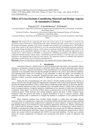
Figure 19. Deformation curve Figure 20. Stress distribution curve
The magnitude of stress and deformation are greater when compared to other polymer composites.
When compared with C and Box cross sections the I cross section induces very low stress and deformation.
Carbon epoxy and S-glass epoxy material of C and BOX cross section as high stress and deformation when
compare to I cross section [24]. Fig. 19 and 20 indicates the deformation and stress distribution curve for the
analysis performed on various materials with cross sections like steel, carbon epoxy and S-glass epoxy
composite. From the above curve it is clear that S-glass epoxy has high deformation and stress distribution when
compared to carbon epoxy polymeric composite and steel. Carbon epoxy and steel chassis gives almost nearer
value especially „I‟ cross section. But carbon epoxy polymeric composite induces very low level of deformation
and stress distribution when compared with steel. I-Cross section provides low deformation and stress
distribution when compared to other cross sections like C and Box. Carbon epoxy composites have low weight
when compared to steel.
VI. Conclusion
The existing heavy vehicle chassis of EICHER is taken for design and analysis with different cross
sections for different materials like Carbon/Epoxy and S-glass /Epoxy composites is performed. The model of
the chassis was created in Pro-E and analysed with ANSYS for same load conditions. After analysis a
comparison is made between existing conventional steel chassis and composite materials in terms of deflections
and stresses, to select the best one. The results of the steel and polymeric composites material with cross section
C, I, and Box are performed. It is inferred that by employing a carbon epoxy composites heavy vehicle chassis
for same load carrying capacity, there is a reduction in weight when compared to steel. Carbon epoxy induces
low deformation and stress distribution when compared to S-glass epoxy composite material and steel especially
in „I‟ section. Based on the results it was inferred that carbon epoxy composites with „I‟ section has superior
strength to withstand high load and induced low deformation and stress distribution when compared to steel and
composite material and other cross sections.
References
[1] Ravi Chandra, M., Sreenivasulu, S., Syed Altaf Hussain, “Modeling and Structural analysis of heavy vehicle chassis made of
polymeric composite material by three different cross sections”, International Journal of Modern Engineering Research, Vol. 2,
Issue. 4, July-August 2012, pp, 2594-2600.
[2] Hemant, B., Patil, Sharad, D., Kachave, Eknath, R., Deore, “Stress Analysis of Automotive Chassis with Various Thicknesses”,
IOSR Journal of Mechanical and Civil Engineering, Vol. 6, Issue. 1, March - April 2013, PP, 44-49.
[3] Hirak Patel, Khushbu, C., Panchal, Chetan S., Jadav, “Structural Analysis of Truck Chassis Frame and Design Optimization for
Weight Reduction”, International Journal of Engineering and Advanced Technology, Vol. 2, Issue. 4, April 2013.
[4] Ashutosh Dubey and Vivek Dwivedi, “Vehicle Chassis Analysis: Load Cases & Boundary Conditions for Stress Analysis”, 11th
National Conference on Machines and Mechanisms, IIT, Delhi, India, December 2003.
[5] Abhishek Singh, Vishal Soni, Aditya Singh, “Structural Analysis of Ladder Chassis for Higher Strength”, International Journal of
Emerging Technology and Advanced Engineering, Vol. 4, Issue. 2, February 2014.
[6] Anand Gosavi, Ashish Kumar Shrivastava, Ashish Kumar Sinha, “Structural analysis of six axle trailer frame design and
modification for weight reduction”, International Journal of Emerging Technology and Advanced Engineering, Vol. 4, Issue.
1, January 2014.
[7] Haval Kamal Asker, Thaker Salih Dawoodl and Arkan Fawzi Said, “stress analysis of standard truck chassis during Ramping on
block using finite element method”, ARPN Journal of Engineering and Applied Sciences, Vol. 7, No. 6, June 2012.
[8] Monika, S., Agrawal, Razik, Md., “Finite Element Analysis of Truck Chassis”, International Journal of Engineering Sciences &
Research Technology, Agrawal, 2(12), December 2013.
[9] Deulgaonkar, V.R., Dr. Matani, A.G., Dr. Kallurkar, S.P., “Advanced Mathematical Analysis of Chassis Integrated Platform
Designed for Unconventional loading by using simple technique for static load”, International Journal of Engineering and
Innovative Technology, Vol. 1, Issue. 3, March 2012.
[10] Kurdi, O., Abd- Rahman, R., Tamin, M. N., “Stress Analysis of Heavy Duty Truck Chassis Using Finite Element Method”, 2nd
Regional Conference on Vehicle Engineering & Technology, Universiti Teknologi Malaysia Institutional, Kuala Lumpur, Malaysia,
2008.](https://image.slidesharecdn.com/j012518692-160726082232/85/J012518692-6-320.jpg)
![Effect of Cross-Sections Considering Material and Design Aspects in Automotive Chassis
DOI: 10.9790/1684-12518692 www.iosrjournals.org 92 | Page
[11] Balbirsingh, R., Guron, Dr. Bhope, D.V., Prof. Yenarkar, Y. L., “Finite Element Analysis of Cross Member Bracket of Truck
Chassis”, IOSR Journal of Engineering, Vol. 3, Issue. 3 March 2013, PP, 10-16.
[12] Paul, I. D., Sarange, S. M., Bhole, G. P., and Chaudhari, J. R., “Structural Analysis Of Truck Chassis Using Finite Element
Method”, International J.of Multidispl.Research & Advcs. in Engg, Vol. 4, No. I January 2012, pp, 85-98.
[13] Harshad, K., Patel, Prof. Tushar, M., Patel, “ Structural Optimization Using FEA-DOE Hybrid Modeling –A Review”,
International Journal of Emerging Technology and Advanced Engineering, Vol. 3, Issue. 1, January 2013.
[14] Roslan Abd Rahman, Mohd Nasir Tamin, Ojo Kurdi, “Stress Analysis Of Heavy Duty Truck Chassis As A Preliminary Data For Its
Fatigue Life Prediction Using Fem”, Jurnal Mekanikal, No. 26, December 2008 pp, 76 – 85.
[15] Goolla Murali, Subramanyam, B., Dulam Naveen, “Design Improvement of a Truck Chassis based on Thickness”, Altair
Technology Conference, India, 2013.
[16] Dr. Rajappan, R., Vivekanandhan, M., “Static and Model Analysis of Chassis By Using FEA”, Proceedings of the “National
Conference on Emerging Trends In Mechanical Engineering 2013”.
[17] Sairam Kotari, Gopinath, V., “Static and Dynamic Analysis on Tatra Chassis”, International Journal of Modern Engineering
Research, Vol. 2, Issue. 1, pp, 086-094.
[18] Kim, H. S., Hwang, Y. S., Yoon, H. S., “Dynamic Stress Analysis of a Bus Systems”, Commercial Vehicle Engineering & Research
Center, Hyundai Motor Company, 772-1, Changduk, Namyang, Whasung, Kyunggi-Do, Korea.
[19] Sandip Godse, Prof. Patel, D.A., “Static Load Analysis Of Tata Ace Ex Chassis And Stress Optimisation Using Reinforcement
Technique”, International Journal of Engineering Trends and Technology, Vol. 4, Issue. 7, July 2013.
[20] Dr. Rajappan, R., Vivekanandhan, M., “Static and Modal Analysis of Chassis by Using FEA”, The International Journal Of
Engineering And Science, Vol. 2, Issue. 2, 2013, pp, 63-73.
[21] Tushar, M., Patel, Dr. Bhatt, M. G., and Harshad, K., Patel, “Analysis and validation of Eicher 11.10 chassis frame using Ansys”,
International Journal of Emerging Trends & Technology in Computer Science, Vol. 2, Issue. 2, March - April 2013.
[22] Salvi Gauri Sanjay, Kulkarni Abhijeet, Gandhi Pratik Pradeep, Baskar, P, “Finite Element Analysis of Fire Truck Chassis for Steel
and Carbon Fiber Materials”, Journal of Engineering Research and Applications, Vol. 4, Issue. 7, Version. 2, July 2014, pp, 69-
74.
[23] Vijayan.S.N, S.Sendhilkumar, “Structural Analysis of Automotive Chassis Considering Cross-Section and Material”, International
Journal of Mechanical Engineering and Automation, Volume 2, Number 8, 2015, pp. 370-376.
[24] Vijayan.S.N, S.Sendhilkumar, Kiran babu.K.M, “Design and Analysis of Automotive Chassis Considering Cross-Section and
Material”, International Journal of Current Research, Vol.7, Issue, 05, pp.15697-15701, May, 2015.
Appendix – I
Specifications of heavy vehicle chassis
PARAMETERS VALUE
Material of the chassis Steel 52
Chemical composition 0.20%C, 0.50%Si, 0.9%Mn, 0.03%P
and 0.025%S
Side bar of the chassis 200mm x 76 mm x 6mm
Cross bar of the chassis 180mm x 75 mm x 4mm
Front Overhang (a) 935 mm
Wheel Base (b) 3800 mm
Rear Overhang (c) 1620 mm
Young‟s modulus E 2 x 10⁵
N / mm2
Poisson Ratio 0.3
Radius of Gyration R
Width of the chassis
100 mm
80 mm](https://image.slidesharecdn.com/j012518692-160726082232/85/J012518692-7-320.jpg)

This document discusses the structural analysis of different cross-section designs and composite materials for an automotive chassis to reduce weight. The chassis of an existing heavy vehicle is modeled and analyzed using various polymer composite materials (carbon/epoxy and S-glass/epoxy) and cross-sections (C, I, box). Numerical analysis is performed and results are validated against analytical calculations. Analysis shows that a carbon/epoxy composite chassis with an I-cross section induces lower deformation and stress compared to other materials and designs, making it superior for withstanding high loads.