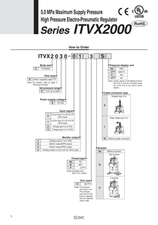
1. This document provides information on the ITVX2000 series high pressure electro-pneumatic regulator including its specifications, operating principles, and safety precautions.
2. The regulator can control air, nitrogen, oxygen, or argon pressure from 0.01 to 3 MPa with a maximum supply pressure of 5 MPa. It has analog and switch outputs for monitoring.
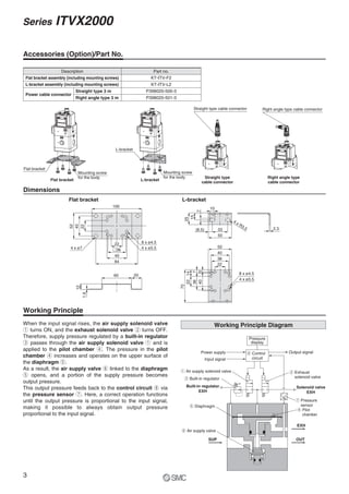
3. The regulator works by using solenoid valves and a built-in regulator to control the pressure in a pilot chamber, which then regulates the air supply valve to maintain a set output pressure proportional to the input signal.
![Application example
Laser beam machine
Series ITVX
High Pressure Electro-Pneumatic Regulator
This product is only for blowing gas. This product does not have sufficient pressure control for other
applications (driving, sealing, etc.).
5.0 MPa
0.01 to 3.0 MPa
3000 L/min [ANR]
Air, N2, O2, Ar
Maximum supply pressure: 5.0 MPa
Set pressure range: 0.01 to 3.0 MPa
Maximum flow rate: 3000 L/min [ANR]
Fluid: Air, N2, O2, Ar
Wetted parts: Fluorine grease
Stepless control of air pressure proportional to an electrical signal
O2
Air
High
pressure N2
Supply pressure: 5.0 MPa Set pressure: 3.0 MPa
5.0 MPa Maximum Supply Pressure
Digital pressure
display
NewNew
RoHS
Power
consumption
3W or less3W or less
Caution
CAT.ES60-21A](https://image.slidesharecdn.com/itvx-150205033409-conversion-gate01/85/Itvx-1-320.jpg)
![Application example
Laser beam machine
Series ITVX
High Pressure Electro-Pneumatic Regulator
This product is only for blowing gas. This product does not have sufficient pressure control for other
applications (driving, sealing, etc.).
5.0 MPa
0.01 to 3.0 MPa
3000 L/min [ANR]
Air, N2, O2, Ar
Maximum supply pressure: 5.0 MPa
Set pressure range: 0.01 to 3.0 MPa
Maximum flow rate: 3000 L/min [ANR]
Fluid: Air, N2, O2, Ar
Wetted parts: Fluorine grease
Stepless control of air pressure proportional to an electrical signal
O2
Air
High
pressure N2
Supply pressure: 5.0 MPa Set pressure: 3.0 MPa
5.0 MPa Maximum Supply Pressure
Digital pressure
display
NewNew
RoHS
Power
consumption
3W or less3W or less
Caution
CAT.ES60-21A](https://image.slidesharecdn.com/itvx-150205033409-conversion-gate01/75/Itvx-1-2048.jpg)
![Linearity
0 25 50 75 100
Setpressure(MPa)
Input signal (%F.S.)
Out
Return
0.0
0.5
1.0
1.5
2.0
2.5
3.0
3.5
Series ITVX2000
Hysteresis
0 25 50 75 100
Outputdeviationfactor(%F.S.)
Input signal (%F.S.)
−1.0
−0.5
0.0
0.5
1.0
Repeatability
0 1 2 3 4 5
Outputdeviationfactor(%F.S.)
Count
Out
Set point
Return
−1.0
−0.5
0.0
0.5
1.0
Flow-rate Characteristics
0 500 1,000 1,500 2,000
Setpressure(MPa)
Flow rate (L/min [ANR])
0.0
0.1
1.0
0.2
0.3
0.4
0.5
0.6
0.7
0.8
0.9
Pressure Characteristics
0.4 0.6 0.8 1.0 1.2
Outputdeviationfactor(%F.S.)
Supply pressure (MPa)
Set pressure: 0.4 MPa
Supply pressure: 1.0 MPa
−1.0
−0.5
0.0
0.5
1.0
4
Series ITVX2000
5.0 MPa Maximum Supply Pressure
High Pressure Electro-Pneumatic Regulator](https://image.slidesharecdn.com/itvx-150205033409-conversion-gate01/85/Itvx-5-320.jpg)
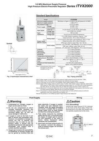
![Handling Design/Selection
Caution
1. The direct-current power supply to combine should
be UL authorized power supply.
1) Limited voltage current circuit in accordance with UL508.
A circuit in which power is supplied by the secondary coil of a
transformer that meets the following conditions.
• Maximum voltage (with no load):
30 [Vrms] (42.4 [V peak]) or less
• Maximum current:
1. 8 [A] or less (including when short circuited)
2. Limited by circuit protector (such as fuse) with the follow-
ing ratings
2) A circuit using max. 30 [Vrms] or less (42.4 [V peak]), which is
powered by UL1310 or UL1585 compatible Class-2 power
supply.
2. Operate these products only within the specified
voltage.
Using voltages beyond the specified levels could cause faults
or malfunctions.
3. Use 0 V as the baseline for the power supplied to this
product for output, control and input.
0 V
Output power
Control/Input power
+24 V
+24 V
0 V
Output power
Control/Input power
–24 V
+24 V
No load voltage [V peak]
0 to 20 [V]
Over 20 [V] to 30 [V]
Max. current rating [A]
5.0
100
Peak voltage
Caution
1. Do not use a lubricator on the supply side of this
product, as this can cause a malfunction.
2. If electric power is shut off due to a power failure or
any reason while the product is being controlled, air
supply at the set pressure will be continuously
consumed.
3. If supply pressure to this product is interrupted
while the power is still on, the internal solenoid
valve will continue to operate and a humming noise
may be generated. Since the life of the product may
be shortened, shut off the power supply also when
supply pressure is shut off.
4. Do not block three EXH ports on this product.
5. This product does not have a shut-off valve
function. If air pressure is supplied without electric
power being applied, output pressure may increase
to the pressure equivalent of the supply pressure.
Due to product construction, a very small amount
of air is discharged from the exhaust port when
output pressure is generated. Operate the system
to shut off the supply pressure when not operating
the product.
6. The product is adjusted to each specification at the
time of shipment from the factory. Do not perform
unnecessary disassembly or removal of parts as it
will cause failure.
7. The optional cable connector is a 4-core wire type.
When the monitor output (analog output or switch
output) is not being used, keep it from touching the
other wires as this can cause a malfunction.
8. Please note that the right angle cable does not rotate
and is limited to only one entry direction.
9. Take the following steps to avoid a malfunction due
to noise.
1) Remove power supply noise during operation by installing a
line filter, etc. in the AC power line.
2) For avoiding the influence of noise or static electricity, install
this product and its wiring as far as possible from strong
electric fields such as those of motors and power lines, etc.
3) Be sure to implement protective measures against load surge
for induction loads (solenoid valves, relays, etc.).
10. For details on the handling of this product, refer to
the operation manual which is included with the
product.
4. Each product needs to be powered by one power
supply unit.
The wiring of this product has the same common between the
GND for power and the signals; there is a possibility that a
wrong current occurs and prevents a proper operation if one
power supply unit controls multiple electro-pneumatic
regulators.
Series ITVX2000
Specific Product Precautions 2
Be sure to read before handling. Refer to back cover for Safety Instructions, “Handling
Precaution for SMC Products” (M-E03-3) and the Operation Manual. Please download it
via our website, http://www.smcworld.com
7](https://image.slidesharecdn.com/itvx-150205033409-conversion-gate01/85/Itvx-8-320.jpg)