Downloaded 168 times


![3 Determining Irrigation Requirements
Step three: Determining mm) per day. These figures are rough estimates for these
irrigation requirements types of climates for an average midsummer day.
To answer the questions “How much water has to be To help determine in which climate your project is located,
applied to the plant material?” and “How often and how consult the notes on “Hot,” “Warm,” or “Cool” that are
long does the system need to run?,” a number of factors listed below the PET table. Also listed are the humidity
need to be examined. ranges that establish the “Humid” and “Dry” classifications.
An irrigation system should always be designed to
The local climate is one of the main factors that influences adequately water the project in the “worst case” condition.
how much water is needed to maintain good plant growth. This is usually midsummer when the average daily
The plant water requirement includes the water lost by temperature is at or near its highest for the growing season
evaporation into the atmosphere from the soil and soil or when humidity is averaging its lowest percentages. Of
surface, and by transpiration, which is the amount of water course, a combination of these extremes produces the
used by the plant. The combination of these is greatest water requirement. When you have determined
evapotranspiration (ET). the climate type for the area where your project is located,
ETo stands for reference evapotranspiration, which is the use the highest number, the “worst case” condition listed at
maximum average rate of water use for plants in a given the top of the ET range for that climate type, as the
climate. Reference evapotranspiration is multiplied by a requirement for your project.
crop coefficient to obtain the ET rate for a specific plant or We will be discussing the precipitation rate of sprinklers
turf. Although it is a rough guide to water requirements and later in the design process. Choosing sprinklers to match
not geared to a specific plant, the table below and in the the irrigation requirement is a critical consideration for the
Technical Data section of this manual will help establish a designer. Later in this manual, we will also consider
ball park figure for your project. At the design stage, the matching the scheduling of automatic irrigation controls to
designer wants to provide an irrigation system that can both the sprinkler precipitation rate and the system
meet peak season (summer time) ET rates. irrigation requirement.
In the table, note the factors that affect the water use rate The soil type on the project site is a factor in determining
for a given climate type. The three categories of “Cool,” how fast and how often water can be applied to the plant
“Warm” and “Hot” indicate that temperature has an material.
influence on water use. The hotter the climate, the more
water loss is expected. Other major factors are humidity
and wind speed. If the air is humid, evaporation will be Soil type
lower as compared to a climate with the same average Soil absorbs and holds water in much the same way as a
temperature but drier air. sponge. A given texture and volume of soil will hold a given
amount of moisture. The intake rate of the soil will
Climate PET
influence the precipitation rate and type of sprinkler that
Climate Inches (millimeters) Daily can be utilized. The ability of soil to hold moisture, and the
Cool Humid .10 to .15 in (3 to 4 mm)
amount of moisture it can hold, will greatly affect the
Cool Dry .15 to .20 in (4 to 5 mm)
irrigation operational schedule.
Warm Humid .15 to .20 in (4 to 5 mm)
Warm Dry .20 to .25 in (5 to 6 mm) Soil is made up of sand, silt and clay particles. The
Hot Humid .25 to .30 in (6 to 8 mm) percentage of each of these three particles is what
Hot Dry .30 to .45 in (8 to 11 mm) “worst case” determines the actual soil texture. Because the percentage
Cool = under 70° F (21˚ C) as an average midsummer high of any one of these three particles can differ, there is
Warm = between 70° and 90° F (21˚ and 32˚ C) as midsummer highs virtually an unlimited number of soil types possible.
Hot = over 90° F (32˚C)
Humid = over 50% as average midsummer relative humidity [dry = under 50%] The simplest way to determine the soil type is to place a
moistened soil sample in your hand and squeeze. Take the
In the table, a “Cool Humid” climate has an ET range in sample from a representative part of the site, and from
inches (millimeters) of water required per day of .10 to .15 approximately the same depth to which you will be
in (3 to 4 mm). At the upper end of the scale, a “Hot Dry” watering. In other words, if you want to water to a depth of
climate produces a requirement of .30 to .45 in (8 to 11 6 in (15 cm), dig down 6 in (15 cm) to take your soil sample.
Landscape Irrigation Design Manual 19](https://image.slidesharecdn.com/10134907-111112145000-phpapp01/75/Irrigation-Design-Manual-27-2048.jpg)


![Selecting Sprinklers and Spacing Ranges
through the parallelogram patterns to triangular behind this to gallons per hour we need to multiply by 60 minutes.
second base, and continue sliding back through the To work this into the constant, we multiply 1.604 in x 60 min
patterns to rectangular again behind first base. This sliding and we come up with the 96.3 for the formula. (In the
method of spacing the sprinklers would continue right out International System Units version of the formula, because
to the part-circle sprinklers along the outfield fence. the multipliers already are in meters cubed per hour, you do
not need to convert the 1000 before using it in the formula.)
If the designer knows how many inches (millimeters) of
water per week or per day will be required to properly Let’s look at an example of a precipitation rate calculation
maintain the plant material for the project, the next thing to for four full circle impact sprinklers. Each sprinkler has a
know is the rate at which the sprinklers will apply the water. radius of throw of 40 ft (12 m) at 40 psi (3 bar), a discharge
The precipitation rate of the sprinklers selected should be of 4.4 gpm (1 m3/h) and the sprinklers are spaced at 40 ft
calculated to determine first if the rate exceeds the soil’s (12 m) square spacing. The diagram of the sprinkler pattern
intake rate (which it shouldn’t) and, secondly, if the rate will would look like Figure 43.
apply enough water during acceptable operating times to
Each full circle sprinkler delivers only 1/4 of its flow into
meet the irrigation requirement (which it should).
the area between the four sprinklers. The other 3/4 of each
The average precipitation rate is expressed in inches per hour sprinkler’s rotation pattern is outside the area. With 4.4
(millimeters per hour). A simple formula is used to calculate gpm (1 m3/h) total per sprinkler, only 1.1 gpm (0,25 m3/h)
precipitation rates for sprinklers using the area inside the is delivered per sprinkler into the area between them.
sprinkler spacing and the gallons per minute (cubic meters per When four sprinklers delivering 1.1 gpm (0,25 m3/h) each
hour) being applied to that area. The formula looks like this: are added together, they are the equivalent of one full circle
sprinkler or 4.4 gpm (1 m3/h). With full circle sprinklers,
PR = 96.3 x gpm (applied to the area)
you can use the equivalent of one sprinkler’s discharge as
SxL the gallons per minute (meters cubed per hour) for the
PR = 1000 x m3/h [applied to the area] precipitation rate formula.
SxL 40 ft
(12 m)
Where:
PR = the average precipitation PR = the average precipitation
rate in inches per hour rate in millimeters per hour
40 ft
96.3 = a constant which 1000 = a constant which (12 m)
incorporates inches per converts meters to
square foot per hour millimeters
gpm = the total gpm applied m3/h = the total m3/h applied
to the area by the to the area by the
sprinklers sprinklers 1.1 gpm (0,25 m3/h) contributed
by each sprinkler to area
S = the spacing between S = the spacing between
sprinklers sprinklers Figure 43: Square sprinkler spacing pattern with full circle sprinkler
L = the spacing between L = the spacing between
The formula for this example would be:
rows of sprinklers rows of sprinklers
PR = 96.3 x 4.4 gpm = 423.72 = .2648 in/h
The constant of 96.3 (1000) is derived as follows:
40 ft x 40 ft 1600
1 gal water = 231 in3 1 ft2 = 144 in2
(1000 mm = 1 m) PR = 1000 x 1 m3/h = 1000 = 6,94 mm/h
12 m x 12 m 144
Question: If one gallon of water was applied to 1 ft2
how deep in inches would the water be? The above calculation tells the designer that the sprinklers
at that spacing, if given the pressure required, will apply
231 in3/gal = 1.604 in deep
water at slightly more that 1/4 in (6,9 mm) per hour. Using
144 in2/ft2 the same 40 ft x 40 ft (12 m x 12 m) spacing that we used
One of the multipliers in the upper half of the equation is earlier, let’s look at those same sprinklers in half circle
the gallons per minute applied by the sprinklers. To convert configuration.
44 Landscape Irrigation Design Manual](https://image.slidesharecdn.com/10134907-111112145000-phpapp01/75/Irrigation-Design-Manual-52-2048.jpg)
![5 Selecting Sprinklers and Spacing Ranges
40 ft S The total amount of water being applied to the area by
(12 m)
these matched precipitation rate spray sprinklers is:
40 ft L Full circle sprinkler = 0.6 gpm (0,14 m3/h) [1/4 of its discharge]
(12 m)
Half circle sprinkler = 0.6 gpm (0,14 m3/h) [1/2 of its discharge]
2.2 gpm (0,5 m3/h) contributed
Half circle sprinkler = 0.6 gpm (0,14 m3/h) [1/2 of its discharge]
by each sprinkler to area
Quarter circle sprinkler = 0.6 gpm (0,14 m3/h) [all of its discharge]
Figure 44: Square sprinkler spacing pattern with part circle sprinkler
Total = 2.4 gpm (0,56 m3/h) applied to the area
With the same performance specs of 4.4 gpm (1 m3/h) per In calculating the rate for this example, the formula would be:
sprinkler and all the sprinklers now set at half circle, the
formula is: PR = 96.3 x 2.4 gpm = 231.12 = 1.75 in/h
PR = 96.3 x 8.8 gpm = 847.44 = .529 in/h 11 x 12 132
40 ft x 40 ft 1600 PR = 1000 x ,56 m3/h = 560 = 46,67 mm/h
PR = 1000 x 2 m3/h = 2000 = 13,89 mm/h 3x4 12
12 m x 12 m 144 Having completed the calculation, the designer knows to
Even though there are eight sprinklers in the diagram, we are expect a precipitation rate of 1.75 in/h (47 mm/h).
only interested in the area between four adjacent sprinklers.
Triangular spacing is just as easy to work with when
The 8.8 gal (2 m3/h) was determined by adding up the part
calculating the precipitation rate as square or rectangular
of the discharge from each sprinkler that it contributed to
spacing. The main difference is calculating the height of the
the area. With each sprinkler in the half circle setting, one
pattern before using it as one of the dimensions in the
half of its flow was distributed into the square pattern while
formula.
the other half went into the neighboring pattern. The
amount of flow per sprinkler, then, was 2.2 gpm (0,5 m3/h) In this example, large size rotor pop-up sprinklers are
multiplied by four sprinklers for a total of 8.8 gpm (2 m3/h). spaced head-to-head at 70 ft (21 m) in a triangular pattern.
The gallons per minute (meters cubed per second) from
Spray sprinklers have fixed arcs of coverage and some have
each of these full circle sprinklers is 27.9 (6,33 m3/h). The
matched precipitation rates. Let’s look at a PR calculation
pattern would look like this:
for four spray sprinklers in the corner of a lawn area with
these statistics:
Spacing: S = 11 ft (3 m), L = 12 ft (4 m)
Operating pressure at the sprinklers = 25 psi (1,7 bar)
Radius of throw = 11 ft (3 m), regardless of pattern
Discharge: Full circle = 2.4 gpm (0,56 m3/h) 70 ft
Half circle = 1.2 gpm (0,28 m3/h) (21 m)
Quarter circle = .6 gpm (0,14 m3/h)
The spacing pattern might look like this: 27.9 gpm each
(6.33 m 3/h)
Full circle Half circle Figure 46: Calculating triangular sprinkler spacing
2.4 gpm 1.2 gpm
(0,56 m3/h) (0,28 m3/h)
One dimension in the spacing pattern is 70 ft (21 m), the
spacing between sprinklers, and the other is the height of
11 ft the pattern, the spacing between rows of sprinklers. This
(3 m)
height is the spacing multiplied by .866. In this case, we
have a height calculation of 70 ft x .866 = 60.62 ft (21 m x
12 ft .866 = 18,19 m). The dimensions to use in the PR formula
(4 m) for this situation are 70 ft x 60.62 ft (21 m x 18,19 m).
Half circle Quarter circle
1.2 gpm .6 gpm
(0,28 m3/h) (0,14 m3/h) The easiest way to calculate the PR for triangular patterns is
Figure 45: PR calculation for four spray heads to treat them as parallelograms, using four sprinklers instead
Landscape Irrigation Design Manual 45](https://image.slidesharecdn.com/10134907-111112145000-phpapp01/75/Irrigation-Design-Manual-53-2048.jpg)


![Selecting Sprinklers and Spacing Ranges
Locating sprinklers on the plan watered along with the turf or ground cover without over
With all that has been covered concerning sprinkler watering, surround it with at least three sprinklers so it
performance, sprinkler spacing and calculating doesn’t affect coverage of the other plantings.
precipitation rates, we are now ready to use this
information to properly locate sprinklers on the plan.
Properly locating the sprinklers is extremely important! An
irrigation system is one of the few items that is purchased
and then buried in the ground. Major problems are difficult
to correct after a system has been installed, and even minor
mistakes in the design or installation phases of the project Figure 49: Sprinkler pattern for hedges
can be costly to correct.
A dense hedge, if not to be watered by bubblers or drip
The goal in positioning the sprinklers is to make sure all irrigation, can often be thrown into by nearby sprinklers. If,
areas that require irrigation have adequate sprinkler instead, bubblers are to be used for trees or hedges, a low
coverage. Remember not to stretch the spacing between flow bubbler should be used (.25 gpm to .50 gpm [0,06 to
sprinklers beyond their recommended ranges. The row of 0,11 m3/h or 0,02 to 0,03 L/s]) or a standard flow bubbler
sprinklers on the project that might be eliminated because (1 gpm [0,23 m3/h or 0,06 L/s] or more) using a basin to
all the other rows were stretched, will cost the system catch any runoff. For information on designing drip
owner many times the money saved on initial installation. irrigation, see the Rain Bird Xerigation Design Manual
To make up for poor coverage, the owner will likely apply (Catalog No. D39030C).
more water. Over the life of the system, much money will
2.Where possible, use the same types of sprinklers over a
be lost in water waste.
given area. Remember the next step after plotting the
Here are some of the things to keep in mind after you have sprinklers is to group them into valve circuits or laterals. If
selected the sprinkler for a particular area: the turf area on your plan is covered by all spray sprinklers
except for rotor pop-ups on one slightly wider spot, the
1. Begin laying out sprinklers in trouble areas first.
rotors will have to be valved separately from those spray
“Trouble areas” are those with odd shapes, prominent
sprinklers. Try not to isolate three or four special sprinklers
obstructions, confined spaces or other features that require
that will require their own valve if it really is not necessary.
special spacing considerations. After establishing the
sprinkler locations in the “trouble areas,” move out into the 3. After locating all the sprinklers on the plan, visually
open areas by using sliding or staggered spacing. check the entire system for proper spacing and good
coverage. This is the time to make any slight adjustments,
add or delete sprinklers and check spacing before drawing
in any pipe routing.
Let’s look at some typical sprinkler-locating methods for
Overthrow handling various types of planting areas.
Small planters and narrow planting beds can usually be
adequately irrigated with drip irrigation, flood bubblers,
stream bubblers or short-radius spray sprinklers. If a
planter is narrow with walled or bermed borders, flood
Figure 48: Sprinkler pattern for shrubs and trees bubblers can be used to fill the reservoir area under the
plants. Slightly wider planting areas can use stream
The exact locations of trees on (or to be planted on) the site
bubblers that can throw gentle streams out to a radius of 5
are important so the designer can provide for them in
ft (1,5 m). Narrow lawn strips can be watered by short-
sprinkler spacing. For trees or large bushes and hedges that
radius spray sprinklers with strip pattern nozzles.
are not to be irrigated separately, the sprinklers in the area
should surround and throw into or under the plants. For Let’s see how the designer handled planters and narrow
the sprinklers spaced too near, this larger foliage acts as a beds in the sample project (see Figure 50). From the
barrier to good distribution. If the tree or large bush can be designer’s plan, we can see that low-flow drip irrigation has
48 Landscape Irrigation Design Manual](https://image.slidesharecdn.com/10134907-111112145000-phpapp01/75/Irrigation-Design-Manual-56-2048.jpg)


![7 Sizing Pipe and Valves and Calculating System Pressure Requirements
This backflow prevention device, along with all the pipe the pipe sizes, a circuit using 1-1/4 in (32 mm) pipe with
and electric valves on the system, will need to be sized. flows equivalent to a neighboring circuit using 2 in (50 mm)
pipe was created. The 1-1/2 in valve will be larger than the
The designer begins by sizing the lateral valves. Because all
lateral it serves, however, the flow justifies using that size
the circuits require the same flow of 39.2 gpm (8,89 m3/h or
unit.
2,47 L/s), this only has to be done once. A few guidelines to
assist you in sizing valves are listed below.
• The flow through the valve should not produce a loss
greater than 10% of the static pressure available in the
main line.
• The valve should either be the same size as the largest
pipe in the lateral it serves, or no more than one
nominal size smaller than that pipe.
• The valve should not be larger than the pipes in the
lateral, unless a high flow (equivalent to a larger size
pipe) results from a split lateral.
In this sample rotor pop-up system, the static pressure at
the meter is 75 psi (5,17 bar). If there are no elevation Figure 66: Remote control valve
changes, then, when we have 75 psi (5,17 bar) static in the
main as well when no water is flowing. We know too, what
One caution about over-sizing automatic valves:
size pipes the valve for each circuit will be serving. So let’s
occasionally, a designer, dealing with low pressures to
size the valves for this system.
begin with, will look for ways to reduce pressure loss. If the
In your equipment catalog, under valves, turn to the PEB designer selects a large size valve because the flow loss is so
Series electric remote control valves. These units are high- low as to be unlisted on the performance chart, he or she
pressure, plastic, 24 volt valves available in three sizes. With may find the valve won’t operate once the system is
a flow of 40 [39.2] gpm (9,07 m3/h or 2,52 L/s) established installed. There must be a minimum pressure loss through
for each circuit we can begin our selection. Rule one says most types of automatic valves! The valves use this pressure
we cannot create a loss through the valve of more that 10% differential to open and close. Lack of data in the
of the 75 psi (5,17 bar) static pressure when flowing the 40 manufacturer’s performance chart is an indicator that the
gpm (9,07 m3/h or 2,52 L/s). valve should not be used at the high or low flows in
question.
Looking at the performance chart for the PEB series valves
(see page 68), we search for a size with a loss equal to or Getting back to our sample rotor job, we have selected the
less than 7.5 psi (0,52 bar) when flowing 40 gpm (9,07 m3/h 150-PEB, 1-1/2 in valve, for Circuits #1 and #2. The rest of
or 2,52 L/s). At that flow, the 1 in valve has a loss of 9.3 psi the circuits on the plan are just like Circuit #1, so all the
(0,64 bar), which is too high for this system. The next size valves on the project will be 150-PEB valves. If there were
up, 1-1/2 in (40 mm), shows a loss of 1.9 psi (0,13 bar) at 40 circuits requiring various flows on the project, they would
gpm (9,07 m3/h or 2,52 L/s) flow. This size fits our 10% or use differing valve sizes, selected using the same sizing
less static pressure loss rule. rules.
Rule number two says the valve should be the same size, or
The main line from the meter to the last valve now needs to
not more than one nominal size smaller, than the largest
be sized. Main lines need good, high-strength walls
pipe in the lateral. Sample Circuit #1 calls for the valve to
because they are under constant pressure. Let’s say the
feed a 2 in (50 mm) pipe. The 1-1/2 in valve satisfies this
designer has chosen Schedule 40 PVC pipe. Turning to that
rule, being one size smaller than the pipe served.
chart in the Technical Data section, the designer would
Rule number three applies to sample Circuit #2. Because look for the smallest size that will flow 40 gpm (9,07 m3/h
the designer split the circuit to balance the flow and reduce or 2,52 L/s) at a velocity of 5 ft/s (1,5 m/s) or less.
Landscape Irrigation Design Manual 67](https://image.slidesharecdn.com/10134907-111112145000-phpapp01/75/Irrigation-Design-Manual-75-2048.jpg)


![7 Sizing Pipe and Valves and Calculating System Pressure Requirements
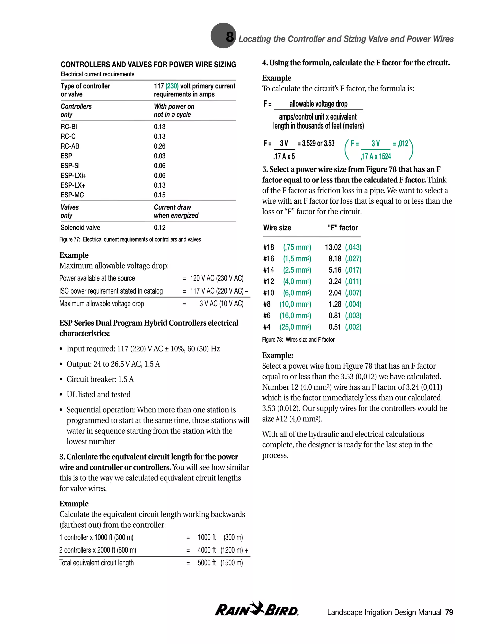
Exercises on calculating system • for 39.2 gpm (8,89 m3/h or
pressure requirements 2,47 L/s) through a 1-1/2 in
The procedure is outlined below to work backward from (40 mm) water meter ______________+
the “worst case” sprinkler of the “worst case” lateral, and • estimate for fittings loss:
hence all the way through the system main line until we 10% of all pipe losses ______________+
determine the minimum pressure requirement (75 psi
• any losses in pressure due to
[5,17 bar] in front of the water meter). In this case, we
elevation rise ______________+
created an imaginary “worst case” lateral by calculating
losses as if Circuit #1 was farther out on the main line
where Circuit #2 is. Remember this change if, after filling
Subtotal ______________+
in the blanks, you wish to follow the critical length of the
system we are analyzing. • any pressure gains from
elevation drop ______________+
Fill in the blanks. Assume the site is flat and has no
elevation change. Total pressure required by
the system ______________+
Pressure needed at sprinkler = 55 psi (3,79 bar)
Static pressure available to
Pressure loss: the site 75 psi (5,17 bar)+
• for 9.8 gpm (2,22 m3/h or Total pressure required by
0,62 L/s) through 47 ft the system 75 psi (5,17 bar)+
(14,3 m) of 3/4 in (20 mm) If this is a positive number,
Class 200 PVC pipe ______________+ the system will work ______________+
• for 19.6 gpm (4,45 m3/h or In looking at the residential plan we have also been
1,24 L/s) through 47 ft (14,3 m) following, we can see the designer had a high pressure
of 1-1/4 in (32 mm) Class 200 situation to deal with. With 111 psi (7,7 bar) at the meter
PVC pipe ______________+ and sprinklers requiring between 15 and 20 psi (1,03 and
• for 29.4 gpm (6,67 m3/h or 1,38 bar) to operate, there was “pressure to burn.” Rather
1,85 L/s) through 47 ft (14,3 m) than specifying very small pipe sizes that could cause high
of 1-1/2 in (40 mm) Class 200 velocity and/or surge pressure problems, the designer
PVC pipe ______________+ called for a main line pressure regulator. This component
• for 39.2 gpm (8,89 m3/h or can be set for a specific downstream pressure in the main
2,47 L/s) through 23.5 ft (7,2 m) line. This reduces the amount of pipe on the project that is
of 2 in (50 mm) Class 200 PVC subjected to high pressure and provides for a beginning
pipe ______________+ pressure that is closer to the sprinklers’ performance range.
• for 39.2 gpm (8,89 m3/h or In addition, the electric valves selected for the project have
2,47 L/s) through a 150-PEB, their own individual lateral pressure regulators. For the low
1-1/2 in electric valve ______________+ application or drip watering circuits, these are fixed-outlet
pressure regulators. As for the sprinkler circuits, they are
• for 39.2 gpm (8,89 m3/h or
the adjustable type. In this way, the designer has put
2,47 L/s) through 162.8 ft
complete pressure control into the system.
(50 m) of 2 in (50 mm)
Schedule 40 PVC pipe ______________+ Before we go on, there is one quick way for sizing pipe that
So far, the above is Circuit #1 + 40.7 ft (14,3 m) added to the is often used by designers. Instead of referring again and
main line as if it was farther out where Circuit #2 is located. again to a pipe chart, the designer can build a chart for flow
ranges. To do this, take the pipe chart for the lateral pipe
• for 39.2 gpm (8,89 m3/h or and make a quick note of the top flow for each size of pipe
2,47 L/s) through a PVB-125, before it enters the shaded area on the chart. The resulting
1-1/4 in (32 mm) backflow unit ______________+ chart for Class 200 PVC pipe would look like this:
Landscape Irrigation Design Manual 71](https://image.slidesharecdn.com/10134907-111112145000-phpapp01/75/Irrigation-Design-Manual-79-2048.jpg)


![td Technical Data
Pressure loss in valves and fittings
Equivalent length in feet of standard steel pipes
Nominal Globe Angle Sprinkler Gate Side outlet Run of Std. 45
pipe size valve valve angle valve valve std. tee std. tee elbow elbow
1/2 17 9 2 0.4 4 1 2 1
3/4 22 12 3 0.5 5 2 3 1
1 27 15 4 0.6 6 2 3 2
1 1/4 38 18 5 0.8 8 3 4 2
U.S. Standard Units
1 1/2 45 22 6 1.0 10 3 5 2
Technical Data
2 58 28 7 1.2 12 4 6 3
2 1/2 70 35 9 1.4 14 5 7 3
3 90 45 11 1.8 18 6 8 4
4 120 60 15 2.3 23 7 11 5
6 170 85 20 3.3 33 12 17 8
Pressure loss through copper and bronze fittings
Equivalent feet of straight tubing
Wrought copper Cast bronze
Nominal 90° 45° Tee Tee Side 90° 180° 90° 45° Tee Tee Side Compression
Tube Size Elbow Elbow Run Outlet Bend Bend Elbow Elbow Run Outlet Stop
3/8 1/2 1/2 1/2 1 1/2 1/2 1 1/2 1/2 2 9
1/2 1/2 1/2 1/2 1 1/2 1 1 1 1/2 2 13
5/8 1/2 1/2 1/2 2 1 1 2 1 1/2 3 17
3/4 1 1/2 1/2 2 1 2 2 1 1/2 3 21
1 1 1 1/2 3 2 2 4 2 1/2 5 30
11/4 2 1 1 4 2 3 5 2 1 7 —
11/2 2 2 1 5 2 4 8 3 1 9 —
2 2 2 1 7 3 8 11 5 2 12 —
21/2 2 3 2 9 4 16 14 8 2 16 —
3 3 4 — — 5 20 18 11 2 20 —
11/2 4 — — — 7 24 24 14 2 31 —
4 — — — — 8 28 28 17 2 37 —
5 — — — — 10 37 41 22 2 48 —
6 — — — — 13 47 52 28 2 61 —
Climate PET Estimated service line sizes
Climate Inches Daily Length of
Cool Humid .10 to .15 in 2 3/4 in 3 1/4 in 3 1/2 in 4 in 4 3/8 in 5 in
string
Cool Dry .15 to .20 in Size of service 3/4 in 1 1/4 in
Warm Humid .15 to .20 in line copper 1 in
Warm Dry .20 to .25 in
Size of service
Hot Humid .20 to .30 in line galvanized
3
/4 in 1 in 1 1/4 in
Hot Dry .30 to .45 in “worst case”
Cool = under 70° F as an average midsummer high
Warm = between 70° and 90° F as midsummer highs
Hot = over 90° F
Humid = over 50% as average midsummer relative humidity [dry = under 50%]
Landscape Irrigation Design Manual 103](https://image.slidesharecdn.com/10134907-111112145000-phpapp01/75/Irrigation-Design-Manual-111-2048.jpg)


![Technical Data
Pressure loss in valves and fittings (in bars)
Equivalent length in meters of standard steel pipes
Nominal Globe Angle Sprinkler Gate Side outlet Run of Std. 45
pipe size valve valve angle valve valve std. tee std. tee elbow elbow
15 mm 5,18 2,74 0,61 0,12 1,22 0,30 0,61 0,30
20 mm 6,71 3,66 0,91 0,15 1,52 0,61 0,91 0,30
25 mm 8,23 4,57 1,22 0,18 1,83 0,61 0,91 0,61
32 mm 11,58 5,49 1,52 0,24 2,44 0,91 1,22 0,61
40 mm 13,72 6,71 1,83 0,30 3,00 0,91 1,52 0,61
50 mm 17,68 8,53 2,13 0,37 3,66 1,22 1,83 0,91
63 mm 21,34 10,67 2,74 0,43 4,27 1,52 2,13 0,91
75 mm 27,43 13,72 3,35 0,55 5,49 1,83 2,44 1,22
110 mm 36,58 18,29 4,57 0,70 7,01 2,13 3,35 1,52
160 mm 51,82 25,91 6,10 1,01 10,06 3,66 5,18 2,44
Pressure loss through copper and bronze fittings (in bars)
Equivalent meters of straight tubing
Wrought copper Cast bronze
Nominal 90° 45° Tee Tee Side 90° 180° 90° 45° Tee Tee Side Compression
Tube Size Elbow Elbow Run Outlet Bend Bend Elbow Elbow Run Outlet Stop
10 mm 0,15 0,15 0,15 0,31 0,15 0,15 0,30 0,15 0,15 0,61 2,74
International System Units
15 mm 0,15 0,15 0,15 0,31 0,15 0,31 0,30 0,31 0,15 0,61 3,96
17 mm 0,15 0,15 0,15 0,61 0,30 0,31 0,61 0,31 0,15 0,91 5,18
Technical Data
20 mm 0,30 0,15 0,15 0,61 0,30 0,61 0,61 0,31 0,15 0,91 6,40
25 mm 0,30 0,30 0,15 0,92 0,61 0,61 1,22 0,61 0,15 1,52 9,14
32 mm 0,61 0,30 0,15 1,23 0,61 0,92 1,52 0,61 0,30 2,13 —
40 mm 0,61 0,61 0,30 1,53 0,91 1,23 2,44 0,92 0,30 2,74 —
50 mm 0,61 0,61 0,30 2,15 1,22 2,45 3,35 1,53 0,61 3,66 —
63 mm 0,61 0,91 0,61 2,76 1,52 4,91 4,27 2,45 0,61 4,88 —
75 mm 0,91 1,22 — — 2,13 6,14 5,49 3,37 0,61 6,10 —
90 mm 1,22 — — — 2,74 7,36 7,32 4,30 0,61 9,45 —
110 mm — — — — — 8,59 8,53 5,22 0,61 11,28 —
130 mm — — — — — 11,35 12,50 6,75 0,61 14,63 —
160 mm — — — — — 14,42 15,85 8,59 0,61 18,59 —
Climate PET Estimated service line sizes
Climate Millimeters Daily Length of
Cool Humid 3 to 4 mm 70 mm 83 mm 89 mm 10,2 cm 11,1 cm 12,7 cm
string
Cool Dry 4 to 5 mm Size of service
Warm Humid 4 to 5 mm line copper 20 mm 25 mm 32 mm
Warm Dry 5 to 6 mm
Size of service
Hot Humid 5 to 8 mm line galvanized
20 mm 25 mm 32 mm
Hot Dry 8 to 11 mm “worst case”
Cool = under 21˚ C as an average midsummer high
Warm = between 21˚ and 32˚ C as midsummer highs
Hot = over 32˚C
Humid = over 50% as average midsummer relative humidity [dry = under 50%]
116 Landscape Irrigation Design Manual](https://image.slidesharecdn.com/10134907-111112145000-phpapp01/75/Irrigation-Design-Manual-124-2048.jpg)


![a Appendix
Table of formulas
Calculating water pressure (area is constant):
P = force = F
area A
Calculating water flow (speed):
V= gpm V = 1273,24 x L/s
2.45 x dia2 dia2
Calculating daily average operating time:
OT = I x 60
PR x DA
Calculating pressure needed to operate the system:
PR = PS – (Po + Pls)
Calculating a circuit’s F factor:
F= allowable voltage drop
amps/control unit x equivalent
length in thousands of feet (meters)
Calculating precipitation rates:
PR = 96.3 x gpm (applied to the area) PR = 1000 x m3/h [applied to the area]
SxL SxL
Landscape Irrigation Design Manual 123](https://image.slidesharecdn.com/10134907-111112145000-phpapp01/75/Irrigation-Design-Manual-131-2048.jpg)


This document provides an overview of basic hydraulics concepts for landscape irrigation design. It discusses static water pressure, which refers to pressure in a closed system with no water movement. Static pressure is created by elevating water sources above the point of use through tanks, towers, or reservoirs, or by pressurizing water systems with pumps. The relationship between water pressure (psi or kg/cm2) and elevation (feet or meters of head) is explained. Higher elevations create greater static pressure that can be used to power irrigation systems. Examples are provided to demonstrate how to calculate static pressure from given elevations or pumping pressures.


