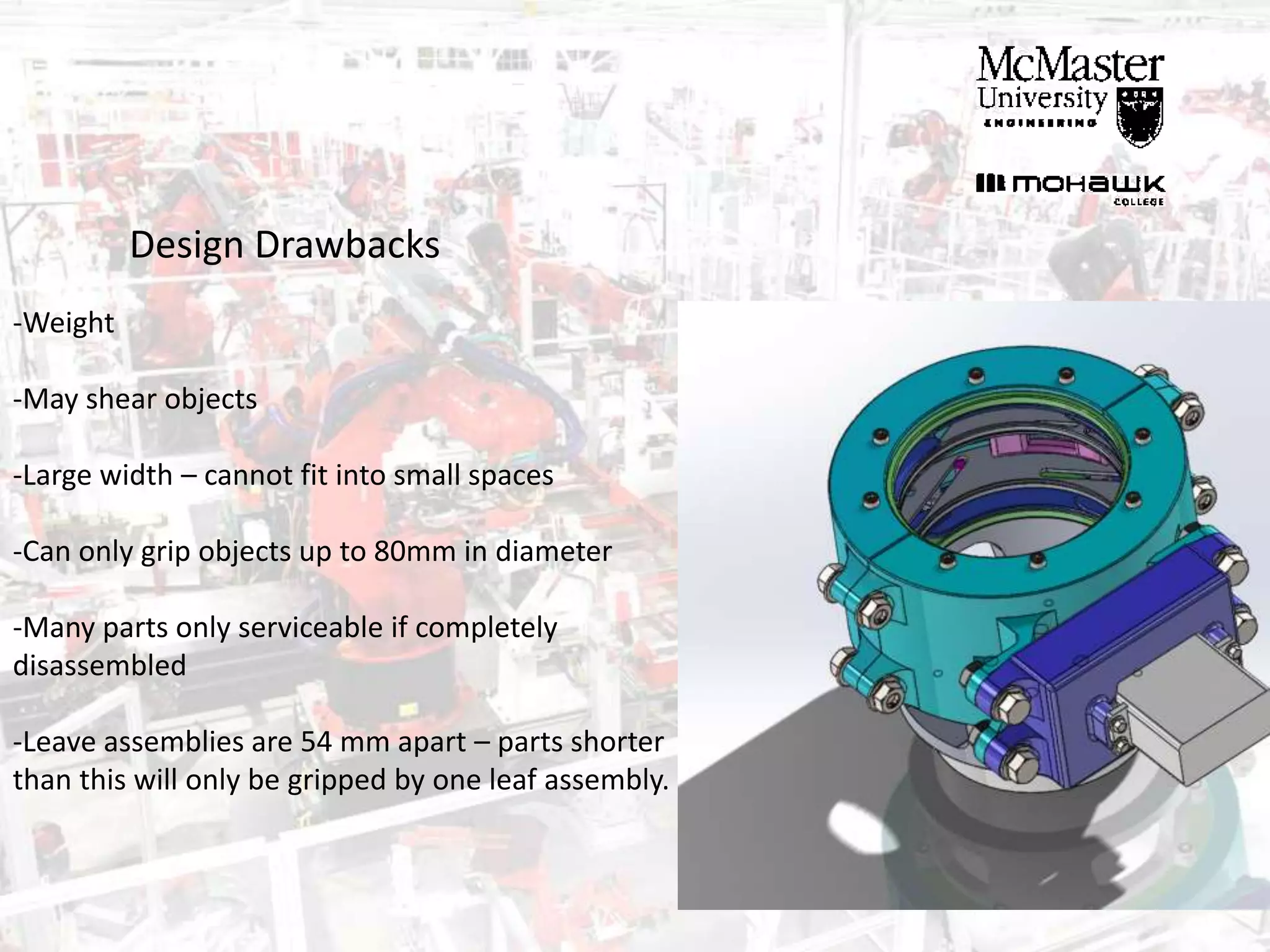
Jack Gillies & Jeremiah Gill
For AUTOTECH 2AC3
Instructor: Lucian Balan
SOLIDWORKS DESIGN
AND SIMULATION
PROJECT
March 19th, 2015
Constraints:
-Must be able to grip 3 prismatic shapes:
-Must be controlled by given servo motor, 5 rotations to close/open
-Must fit onto standard robot tool interface
-All parts must be able to be manufactured
-Assembly without interference
-Must use standard fasteners
-Robust and self-contained
Final Design
Final Design
Redesign
- After we finished the modeling, we realized the gripper isn’t
big enough to fit the cube
- We measured the cube face to face and ignored the
hypotenuse length of the cube
- Redesign took about 10 hours – Would have been easier if
we modeled more parametrically.
Final Design
-522.19 grams
-137 parts, 32 Unique parts
-Can grip objects up to 80mm in
width
- 84.3 mm maximum height from
arm interface
- 194 mm maximum width (to back
of servo)
Final Design
Assembly Animation
Inspiration
-Camera Shutter closes equally around central point
-Will make contact without lateral slip with any part.
-Operates by turning overlapping “leaves” towards inside
-Leaves are turned by pins which are driven by a central
turning ring
Initial Design
-5 Leaves overlapping (2mm thick)
-Leaves Spaced by washers of same thickness
-Assembly held in by retaining ring
Initial Design
-5 Pins of varying length (increments of 2mm) to turn the
leaves
-Pins are pushed through slots in turning ring
-Portion of bevel gear drives turning ring
Issues
-Overlap of leaves may cause “tipping” or
rocking of gripped piece
-We decided to mirror whole assembly so 2
apertures grip piece at different heights
Retaining Case
-Revolved profile of all turning parts to
create casing to retain rotational motion
-Mounting features for Motor assembly
-Identical mounting brackets for M6 bolts
-Upper holes machined for M4 screws to
hold in upper leaf base.
-This part will probably have to be casted
in aluminum.
Drive Train
-Total ratio needed is 39/1800 (turning ring degrees
per motor degree)
-Simple bevel gear and pinion would not be suitable
-Additional gears achieve following ratio:
15 𝑃1
41 𝐺1
15 𝑃2
41 𝐺2
18 𝐵𝑃1
120 𝐵𝑃2
≈ 39/1800
-Gearbox created to mount gears from motor to
Retaining case
Drive Train
Turner Synchronization
-Lower turning plate is driven by bevel gear
-Upper turning plate is connected by turner
synchros (shown in pink)
-Assembly is held together with set screws
-Plates slide inside grooves of retaining case
Spacer Cuff
-This part spaces the whole assembly out
from the arm interface
-This allows the gripper to grip taller parts in
closer to the center
Design Drawbacks
-Weight
-May shear objects
-Large width – cannot fit into small spaces
-Can only grip objects up to 80mm in diameter
-Many parts only serviceable if completely
disassembled
-Leave assemblies are 54 mm apart – parts shorter
than this will only be gripped by one leaf assembly.
Questions?

Iris Gripper SolidWorks Design

  • 1.
    Jack Gillies &Jeremiah Gill For AUTOTECH 2AC3 Instructor: Lucian Balan SOLIDWORKS DESIGN AND SIMULATION PROJECT March 19th, 2015
  • 2.
    Constraints: -Must be ableto grip 3 prismatic shapes: -Must be controlled by given servo motor, 5 rotations to close/open -Must fit onto standard robot tool interface -All parts must be able to be manufactured -Assembly without interference -Must use standard fasteners -Robust and self-contained
  • 3.
  • 4.
  • 5.
    Redesign - After wefinished the modeling, we realized the gripper isn’t big enough to fit the cube - We measured the cube face to face and ignored the hypotenuse length of the cube - Redesign took about 10 hours – Would have been easier if we modeled more parametrically.
  • 6.
    Final Design -522.19 grams -137parts, 32 Unique parts -Can grip objects up to 80mm in width - 84.3 mm maximum height from arm interface - 194 mm maximum width (to back of servo)
  • 7.
  • 8.
  • 10.
    Inspiration -Camera Shutter closesequally around central point -Will make contact without lateral slip with any part. -Operates by turning overlapping “leaves” towards inside -Leaves are turned by pins which are driven by a central turning ring
  • 11.
    Initial Design -5 Leavesoverlapping (2mm thick) -Leaves Spaced by washers of same thickness -Assembly held in by retaining ring
  • 13.
    Initial Design -5 Pinsof varying length (increments of 2mm) to turn the leaves -Pins are pushed through slots in turning ring -Portion of bevel gear drives turning ring
  • 14.
    Issues -Overlap of leavesmay cause “tipping” or rocking of gripped piece -We decided to mirror whole assembly so 2 apertures grip piece at different heights
  • 15.
    Retaining Case -Revolved profileof all turning parts to create casing to retain rotational motion -Mounting features for Motor assembly -Identical mounting brackets for M6 bolts -Upper holes machined for M4 screws to hold in upper leaf base. -This part will probably have to be casted in aluminum.
  • 16.
    Drive Train -Total rationeeded is 39/1800 (turning ring degrees per motor degree) -Simple bevel gear and pinion would not be suitable -Additional gears achieve following ratio: 15 𝑃1 41 𝐺1 15 𝑃2 41 𝐺2 18 𝐵𝑃1 120 𝐵𝑃2 ≈ 39/1800 -Gearbox created to mount gears from motor to Retaining case
  • 17.
  • 18.
    Turner Synchronization -Lower turningplate is driven by bevel gear -Upper turning plate is connected by turner synchros (shown in pink) -Assembly is held together with set screws -Plates slide inside grooves of retaining case
  • 19.
    Spacer Cuff -This partspaces the whole assembly out from the arm interface -This allows the gripper to grip taller parts in closer to the center
  • 20.
    Design Drawbacks -Weight -May shearobjects -Large width – cannot fit into small spaces -Can only grip objects up to 80mm in diameter -Many parts only serviceable if completely disassembled -Leave assemblies are 54 mm apart – parts shorter than this will only be gripped by one leaf assembly.
  • 21.