Downloaded 10 times
![Hydrodynamic Analysis in Regular Waves
6
Where
Mx = ρA1(L+2l)
My = ρA1(b1+α-2(b3+b4+2l)+2b2α-1)
mx = ρA1[0.667b2(α2+α-2) + (α2 -1)(b3+b4+2l)]
my = ρA1[2b2(1 - α-1) + (1 – α-2)
Equation of motion :
{x(t), y(t), fe(t)} = {X, Y, Fe}eiωt
(Mb+Mt)x + Bx + ρgSx = fe(t) + ft(t) + fp(t)](https://image.slidesharecdn.com/ipsbuoy-151108191131-lva1-app6891/85/IPS-Buoy-6-320.jpg)
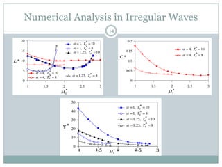
![Numerical Analysis in Irregular Waves
Pierson-Moskowitz spectral distribution :
S(ω) = 526Hs
2 Te
-4 ω-5 exp(-1054 Te
-4 ω-4 )
[ Hs : Significant wave height ; Te: Energy period ]
Time averaged power in irregular wave :
Pirr(Hs , Te) = ∫ Preg(ω) S(ω) dω
Pirr,max = 149.5 Hs
2 Te
3
Non-dimensionalized parameters :
Te
* = Te (g/a)1/2 ; Pirr
* = Pirr/Pirr,max ; D2
* = D2/a
13
0
__
__
__
S(ω) = 526Hs
2 Te
-4 ω-5 exp(-1054 Te
-4 ω-4 )](https://image.slidesharecdn.com/ipsbuoy-151108191131-lva1-app6891/85/IPS-Buoy-13-320.jpg)

![References
17
Falcão AF de O. Wave energy utilization: a review of the technologies. Renew
Sust Energy Rev 2010; 14:899-918.
Masuda Y. Wave-activated generator. Int. colloq. exposition oceans, Bordeaux,
France; 1971.
Noren SA. Apparatus for recovering the kinetic energy of sea waves. US Patent
No. 4,773,221; 1988 [original Swedish Patent No. 8104407; 1981].
Salter SH, Lin CP. Wide tank efficiency measurements on a model of the sloped
IPS buoy. In: Proc. 3rd European wave energy conf., Patras, Greece; 1998. p.
200-6.
Evans DV. The oscillating water column wave-energy device. J Inst Math Appl
1978;22:423-33.
Munson BR, Young DF, Okiishi TH. Fundamentals of fluid mechanics. 2nd ed.
New York: Wiley; 1994
Falnes J. Optimum control of oscillation of wave-energy converters. Int J
Offshore Polar Eng 2002;12:147-55.](https://image.slidesharecdn.com/ipsbuoy-151108191131-lva1-app6891/85/IPS-Buoy-17-320.jpg)


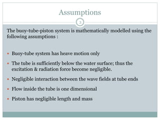
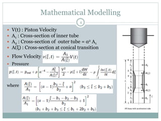
This document describes the hydrodynamic analysis of the IPS Buoy wave energy converter including the effect of non-uniform acceleration tube cross-section. The IPS Buoy system uses the relative motion between a submerged vertical acceleration tube and a piston inside the tube to generate power as they oscillate in heave motion due to incoming waves. The analysis involves developing mathematical models of the system and its components under assumptions like one-dimensional flow inside the tube. Numerical results are presented for the power absorbed and other parameters in regular and irregular wave conditions.


