This document describes a generic process for air vehicle concept design and assessment used by QinetiQ Ltd. The process involves:
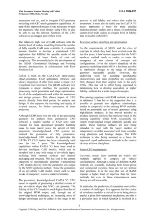
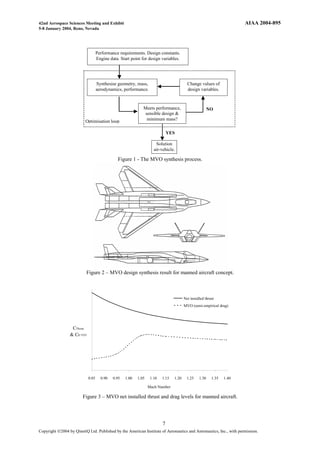
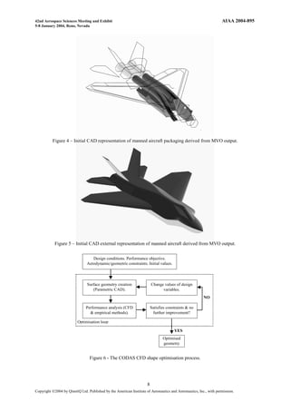
1) Conceptual design using multivariate optimization (MVO) to minimize mass while meeting performance requirements. This provides an initial 2D design.
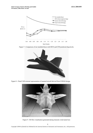
2) Creation of an initial 3D CAD model from MVO output to represent the internal and external geometry.
3) Detailed configuration design using constrained optimization (CODAS) to refine the external surfaces and internal components, improving performance predictions.
Wind tunnel testing then provides performance data, with computational fluid dynamics (CFD) used for additional analysis between design and testing. The process aims to accurately assess novel air vehicle concepts against operational