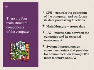
+ Module 1
Introduction
Computer Architecture
•The operational units
and their
interconnections that
realize the architectural
specifications
•Hardware details transparent to the
programmer, control signals,
interfaces between the computer and
peripherals, memory technology
used
•Instruction set, number
of bits used to represent
various data types, I/O
mechanisms, techniques
for addressing memory
•Attributes of a system visible to the
programmer
•Have a direct impact on the logical
execution of a program
Computer
Architecture
Architectural
attributes
include:
Computer
Organization
Organizational
attributes
include:
Computer Organization
+
Structure and Function
 Hierarchical system
 Set of interrelated
subsystems
 Hierarchical nature of complex
systems is essential to both
their design and their
description
 Designer need only deal with
a particular level of the system
at a time
 Concerned with structure
and function at each level
 Structure
 The way in which
components relate to each
other
 Function
 The operation of individual
components as part of the
structure
+
Function
 A computer can perform
four basic functions:
● Data processing
● Data storage
● Data movement
● Control
+
Operations
(a)
Data movement
+
Operations
(b)
Data storage
+
Operations
(c)
Data processing
+
Operations
(d)
Control
The
Computer
Structure
+
 CPU – controls the operation
of the computer and performs
its data processing functions
 Main Memory – stores data
 I/O – moves data between the
computer and its external
environment
 System Interconnection –
some mechanism that provides
for communication among CPU,
main memory, and I/O
There are four
main structural
components
of the computer:
+
CPU
 Control Unit
 Controls the operation of the CPU
and hence the computer
 Arithmetic and Logic Unit (ALU)
 Performs the computer’s data
processing function
 Registers
 Provide storage internal to the CPU
 CPU Interconnection
 Some mechanism that provides for
communication among the control
unit, ALU, and registers
Major structural
components:
+
Computer
Evolution and
Performance
+
History of Computers
 ENIAC
 Electronic Numerical Integrator And Computer
 Designed and constructed at the University of Pennsylvania
 Started in 1943 – completed in 1946
 By John Mauchly and John Eckert
 World’s first general purpose electronic digital computer
 Army’s Ballistics Research Laboratory (BRL) needed a way to supply trajectory tables for
new weapons accurately and within a reasonable time frame
 Was not finished in time to be used in the war effort
 Its first task was to perform a series of calculations that were used to help
determine the feasibility of the hydrogen bomb
 Continued to operate under BRL management until 1955 when it was disassembled
First Generation: Vacuum Tubes
ENIAC
Weighed
30
tons
Occupied
1500
square
feet
of
floor
space
Contained
more
than
18,000
vacuum
tubes
140 kW
Power
consumption
Capable
of
5000
additions
per
second
Decimal
rather
than
binary
machine
Memory
consisted
of 20
accumulators,
each
capable
of
holding
a
10 digit
number
Major
drawback
was the need
for manual
programming
by setting
switches
and
plugging/
unplugging
cables
+
John von Neumann
 First publication of the idea was in 1945
 Stored program concept
 Attributed to ENIAC designers, most notably the mathematician
John von Neumann
 Program represented in a form suitable for storing in memory
alongside the data
 IAS computer
 Princeton Institute for Advanced Studies
 Prototype of all subsequent general-purpose computers
 Completed in 1952
EDVAC (Electronic Discrete Variable Computer)
Structure of von Neumann Machine
+
IAS Memory Formats
 Both data and instructions are
stored there
 Numbers are represented in
binary form and each instruction
is a binary code
 The memory of the IAS
consists of 1000 storage
locations (called words) of
40 bits each
+
Structure
of
IAS
Computer
+ Registers
• Contains a word to be stored in memory or sent to the I/O unit
• Or is used to receive a word from memory or from the I/O unit
Memory buffer register
(MBR)
• Specifies the address in memory of the word to be written from
or read into the MBR
Memory address
register (MAR)
• Contains the 8-bit opcode instruction being executed
Instruction register (IR)
• Employed to temporarily hold the right-hand instruction from a
word in memory
Instruction buffer
register (IBR)
• Contains the address of the next instruction pair to be fetched
from memory
Program counter (PC)
• Employed to temporarily hold operands and results of ALU
operations
Accumulator (AC) and
multiplier quotient
(MQ)
+
IAS
Operations

Introductions and IAS computer.pptx

  • 1.
  • 2.
    Computer Architecture •The operationalunits and their interconnections that realize the architectural specifications •Hardware details transparent to the programmer, control signals, interfaces between the computer and peripherals, memory technology used •Instruction set, number of bits used to represent various data types, I/O mechanisms, techniques for addressing memory •Attributes of a system visible to the programmer •Have a direct impact on the logical execution of a program Computer Architecture Architectural attributes include: Computer Organization Organizational attributes include: Computer Organization
  • 3.
    + Structure and Function Hierarchical system  Set of interrelated subsystems  Hierarchical nature of complex systems is essential to both their design and their description  Designer need only deal with a particular level of the system at a time  Concerned with structure and function at each level  Structure  The way in which components relate to each other  Function  The operation of individual components as part of the structure
  • 4.
    + Function  A computercan perform four basic functions: ● Data processing ● Data storage ● Data movement ● Control
  • 5.
  • 6.
  • 7.
  • 8.
  • 9.
  • 10.
  • 11.
    +  CPU –controls the operation of the computer and performs its data processing functions  Main Memory – stores data  I/O – moves data between the computer and its external environment  System Interconnection – some mechanism that provides for communication among CPU, main memory, and I/O There are four main structural components of the computer:
  • 12.
    + CPU  Control Unit Controls the operation of the CPU and hence the computer  Arithmetic and Logic Unit (ALU)  Performs the computer’s data processing function  Registers  Provide storage internal to the CPU  CPU Interconnection  Some mechanism that provides for communication among the control unit, ALU, and registers Major structural components:
  • 13.
  • 14.
    + History of Computers ENIAC  Electronic Numerical Integrator And Computer  Designed and constructed at the University of Pennsylvania  Started in 1943 – completed in 1946  By John Mauchly and John Eckert  World’s first general purpose electronic digital computer  Army’s Ballistics Research Laboratory (BRL) needed a way to supply trajectory tables for new weapons accurately and within a reasonable time frame  Was not finished in time to be used in the war effort  Its first task was to perform a series of calculations that were used to help determine the feasibility of the hydrogen bomb  Continued to operate under BRL management until 1955 when it was disassembled First Generation: Vacuum Tubes
  • 15.
  • 16.
    + John von Neumann First publication of the idea was in 1945  Stored program concept  Attributed to ENIAC designers, most notably the mathematician John von Neumann  Program represented in a form suitable for storing in memory alongside the data  IAS computer  Princeton Institute for Advanced Studies  Prototype of all subsequent general-purpose computers  Completed in 1952 EDVAC (Electronic Discrete Variable Computer)
  • 17.
    Structure of vonNeumann Machine
  • 18.
    + IAS Memory Formats Both data and instructions are stored there  Numbers are represented in binary form and each instruction is a binary code  The memory of the IAS consists of 1000 storage locations (called words) of 40 bits each
  • 19.
  • 20.
    + Registers • Containsa word to be stored in memory or sent to the I/O unit • Or is used to receive a word from memory or from the I/O unit Memory buffer register (MBR) • Specifies the address in memory of the word to be written from or read into the MBR Memory address register (MAR) • Contains the 8-bit opcode instruction being executed Instruction register (IR) • Employed to temporarily hold the right-hand instruction from a word in memory Instruction buffer register (IBR) • Contains the address of the next instruction pair to be fetched from memory Program counter (PC) • Employed to temporarily hold operands and results of ALU operations Accumulator (AC) and multiplier quotient (MQ)
  • 21.

Editor's Notes

  • #1 This book is about the structure and function of computers. Its purpose is to present, as clearly and completely as possible, the nature and characteristics of modern-day computers. This task is a challenging one for two reasons. First, there is a tremendous variety of products, from single-chip microcomputers costing a few dollars to supercomputers costing tens of millions of dollars, that can rightly claim the name computer. Variety is exhibited not only in cost, but also in size, performance, and application. Second, the rapid pace of change that has always characterized computer technology continues with no letup. These changes cover all aspects of computer technology, from the underlying integrated circuit technology used to construct computer components to the increasing use of parallel organization concepts in combining those components. In spite of the variety and pace of change in the computer field, certain fundamental concepts apply consistently throughout. To be sure, the application of these concepts depends on the current state of technology and the price/performance objectives of the designer. The intent of this book is to provide a thorough discussion of the fundamentals of computer organization and architecture and to relate these to contemporary computer design issues. This chapter introduces the descriptive approach to be taken.
  • #2 In describing computers, a distinction is often made between computer architecture and computer organization. Although it is difficult to give precise definitions for these terms, a consensus exists about the general areas covered by each (e.g., see [VRAN80], [SIEW82], and [BELL78a]); an interesting alternative view is presented in [REDD76]. Computer architecture refers to those attributes of a system visible to a programmer or, put another way, those attributes that have a direct impact on the logical execution of a program. Computer organization refers to the operational units and their interconnections that realize the architectural specifications. Examples of architectural attributes include the instruction set, the number of bits used to represent various data types (e.g., numbers, characters), I/O mechanisms, and techniques for addressing memory. Organizational attributes include those hardware details transparent to the programmer, such as control signals; interfaces between the computer and peripherals; and the memory technology used. For example, it is an architectural design issue whether a computer will have a multiply instruction. It is an organizational issue whether that instruction will be implemented by a special multiply unit or by a mechanism that makes repeated use of the add unit of the system. The organizational decision may be based on the anticipated frequency of use of the multiply instruction, the relative speed of the two approaches, and the cost and physical size of a special multiply unit. Historically, and still today, the distinction between architecture and organization has been an important one. Many computer manufacturers offer a family of computer models, all with the same architecture but with differences in organization. Consequently, the different models in the family have different price and performance characteristics. Furthermore, a particular architecture may span many years and encompass a number of different computer models, its organization changing with changing technology.
  • #3 A computer is a complex system; contemporary computers contain millions of Elementary electronic components. How, then, can one clearly describe them? The key is to recognize the hierarchical nature of most complex systems, including the computer [SIMO96]. A hierarchical system is a set of interrelated subsystems, each of the latter, in turn, hierarchical in structure until we reach some lowest level of elementary subsystem. The hierarchical nature of complex systems is essential to both their design and their description. The designer need only deal with a particular level of the system at a time. At each level, the system consists of a set of components and their interrelationships. The behavior at each level depends only on a simplified, abstracted characterization of the system at the next lower level. At each level, the designer is concerned with structure and function: • Structure: The way in which the components are interrelated. • Function: The operation of each individual component as part of the structure. In terms of description, we have two choices: starting at the bottom and building up to a complete description, or beginning with a top view and decomposing the system into its subparts. Evidence from a number of fields suggests that the top-down approach is the clearest and most effective [WEIN75]. The approach taken in this book follows from this viewpoint. The computer system will be described from the top down. We begin with the major components of a computer, describing their structure and function, and proceed to successively lower layers of the hierarchy. The remainder of this section provides a very brief overview of this plan of attack.
  • #4 Both the structure and functioning of a computer are, in essence, simple. Figure 1.1 depicts the basic functions that a computer can perform. In general terms, there are only four: • Data processing • Data storage • Data movement • Control The computer, of course, must be able to process data. The data may take a wide variety of forms, and the range of processing requirements is broad. However, we shall see that there are only a few fundamental methods or types of data processing. It is also essential that a computer store data. Even if the computer is processing data on the fly (i.e., data come in and get processed, and the results go out immediately), the computer must temporarily store at least those pieces of data that are being worked on at any given moment. Thus, there is at least a short-term data storage function. Equally important, the computer performs a long-term data storage function. Files of data are stored on the computer for subsequent retrieval and update. The computer must be able to move data between itself and the outside world. The computer’s operating environment consists of devices that serve as either sources or destinations of data. When data are received from or delivered to a device that is directly connected to the computer, the process is known as input– output (I/O), and the device is referred to as a peripheral. When data are moved over longer distances, to or from a remote device, the process is known as data communications. Finally, there must be control of these three functions. Ultimately, this control is exercised by the individual(s) who provides the computer with instructions. Within the computer, a control unit manages the computer’s resources and orchestrates the performance of its functional parts in response to those instructions.
  • #5 At this general level of discussion, the number of possible operations that can be performed is few. Figure 1.2 depicts the four possible types of operations. The computer can function as a data movement device (Figure 1.2a), simply transferring data from one peripheral or communication line to another.
  • #6 It can also function as a data storage device (Figure 1.2b), with data transferred from the external environment to computer storage (read) and vice versa (write).
  • #7 The final two diagrams show operations involving data processing, on data either in storage (Figure 1.2c)
  • #8 En route between storage and the external environment (Figure 1.2d).
  • #9 Figure 1.3 is the simplest possible depiction of a computer. The computer interacts in some fashion with its external environment. In general, all of its linkages to the external environment can be classified as peripheral devices or communication lines. We will have something to say about both types of linkages.
  • #10 But of greater concern in this book is the internal structure of the computer itself, which is shown in Figure 1.4. There are four main structural components: Central Processing Unit (CPU) Main Memory I/O System Interconnection
  • #11 There are four main structural components: • Central processing unit (CPU): Controls the operation of the computer and performs its data processing functions; often simply referred to as processor. • Main memory: Stores data. • I/O: Moves data between the computer and its external environment. • System interconnection: Some mechanism that provides for communication among CPU, main memory, and I/O. A common example of system interconnection is by means of a system bus, consisting of a number of conducting wires to which all the other components attach.
  • #12 There may be one or more of each of the aforementioned components. Traditionally, there has been just a single processor. In recent years, there has been increasing use of multiple processors in a single computer. Some design issues relating to multiple processors crop up and are discussed as the text proceeds; Part Five focuses on such computers. Each of these components will be examined in some detail in Part Two. However, for our purposes, the most interesting and in some ways the most complex component is the CPU. Its major structural components are as follows: • Control unit: Controls the operation of the CPU and hence the computer. • Arithmetic and logic unit (ALU): Performs the computer’s data processing functions. • Registers: Provides storage internal to the CPU. • CPU interconnection: Some mechanism that provides for communication among the control unit, ALU, and registers.
  • #13 We begin our study of computers with a brief history. This history is itself interesting and also serves the purpose of providing an overview of computer structure and function. Next, we address the issue of performance. A consideration of the need for balanced utilization of computer resources provides a context that is useful throughout the book. Finally, we look briefly at the evolution of the two systems that serve as key examples throughout the book: the Intel x86 and ARM processor families.
  • #14 The ENIAC (Electronic Numerical Integrator And Computer), designed and constructed at the University of Pennsylvania, was the world’s first general purpose electronic digital computer. The project was a response to U.S. needs during World War II. The Army’s Ballistics Research Laboratory (BRL), an agency responsible for developing range and trajectory tables for new weapons, was having difficulty supplying these tables accurately and within a reasonable time frame. Without these firing tables, the new weapons and artillery were useless to gunners. The BRL employed more than 200 people who, using desktop calculators, solved the necessary ballistics equations. Preparation of the tables for a single weapon would take one person many hours, even days. John Mauchly, a professor of electrical engineering at the University of Pennsylvania, and John Eckert, one of his graduate students, proposed to build a general-purpose computer using vacuum tubes for the BRL’s application. In 1943, the Army accepted this proposal, and work began on the ENIAC.
  • #15 The resulting machine was enormous, weighing 30 tons, occupying 1500 square feet of floor space, and containing more than 18,000 vacuum tubes. When operating, it consumed 140 kilowatts of power. It was also substantially faster than any electromechanical computer, capable of 5000 additions per second. The ENIAC was a decimal rather than a binary machine. That is, numbers were represented in decimal form, and arithmetic was performed in the decimal system. Its memory consisted of 20 accumulators, each capable of holding a 10-digit decimal number. A ring of 10 vacuum tubes represented each digit. At any time, only one vacuum tube was in the ON state, representing one of the 10 digits. The major drawback of the ENIAC was that it had to be programmed manually by setting switches and plugging and unplugging cables. The ENIAC was completed in 1946, too late to be used in the war effort. Instead, its first task was to perform a series of complex calculations that were used to help determine the feasibility of the hydrogen bomb. The use of the ENIAC for a purpose other than that for which it was built demonstrated its general-purpose nature. The ENIAC continued to operate under BRL management until 1955, when it was disassembled.
  • #16 The task of entering and altering programs for the ENIAC was extremely tedious. But suppose a program could be represented in a form suitable for storing in memory alongside the data. Then, a computer could get its instructions by reading them from memory, and a program could be set or altered by setting the values of a portion of memory. This idea, known as the stored-program concept, is usually attributed to the ENIAC designers, most notably the mathematician John von Neumann, who was a consultant on the ENIAC project. Alan Turing developed the idea at about the same time. The first publication of the idea was in a 1945 proposal by von Neumann for a new computer, the EDVAC (Electronic Discrete Variable Computer). In 1946, von Neumann and his colleagues began the design of a new stored program computer, referred to as the IAS computer, at the Princeton Institute for Advanced Studies. The IAS computer, although not completed until 1952, is the prototype of all subsequent general-purpose computers.
  • #17 Figure 2.1 shows the general structure of the IAS computer (compare to middle portion of Figure 1.4). It consists of • A main memory, which stores both data and instructions • An arithmetic and logic unit (ALU) capable of operating on binary data • A control unit, which interprets the instructions in memory and causes them to be executed • Input/output (I/O) equipment operated by the control unit
  • #18 The memory of the IAS consists of 1000 storage locations, called words, of 40 binary digits (bits) each. Both data and instructions are stored there. Numbers are represented in binary form, and each instruction is a binary code. Figure 2.2 illustrates these formats. Each number is represented by a sign bit and a 39-bit value. A word may also contain two 20-bit instructions, with each instruction Consisting of an 8-bit operation code (opcode) specifying the operation to be Performed and a 12-bit address designating one of the words in memory (numbered from 0 to 999).
  • #19 The control unit operates the IAS by fetching instructions from memory and executing them one at a time. To explain this, a more detailed structure diagram is needed, as indicated in Figure 2.3. This figure reveals that both the control unit and the ALU contain storage locations, called registers.
  • #20  Memory buffer register (MBR): Contains a word to be stored in memory or sent to the I/O unit, or is used to receive a word from memory or from the I/O unit. • Memory address register (MAR): Specifies the address in memory of the word to be written from or read into the MBR. • Instruction register (IR ): Contains the 8-bit opcode instruction being executed. • Instruction buffer register (IBR): Employed to hold temporarily the right-hand instruction from a word in memory. • Program counter (PC): Contains the address of the next instruction pair to be fetched from memory. • Accumulator (AC) and multiplier quotient (MQ): Employed to hold temporarily operands and results of ALU operations. For example, the result of multiplying two 40-bit numbers is an 80-bit number; the most significant 40 bits are stored in the AC and the least significant in the MQ.
  • #21 The IAS operates by repetitively performing an instruction cycle, as shown in Figure 2.4. Each instruction cycle consists of two sub-cycles. During the fetch cycle, the opcode of the next instruction is loaded into the IR and the address portion is loaded into the MAR. This instruction may be taken from the IBR, or it can be obtained from memory by loading a word into the MBR, and then down to the IBR, IR, and MAR. Why the indirection? These operations are controlled by electronic circuitry and result in the use of data paths. To simplify the electronics, there is only one register that is used to specify the address in memory for a read or write and only one register used for the source or destination. Once the opcode is in the IR, the execute cycle is performed. Control circuitry interprets the opcode and executes the instruction by sending out the appropriate control signals to cause data to be moved or an operation to be performed by the ALU. Figure 2.4 shows several examples of instruction execution by the control unit. Note that each operation requires several steps. Some of these are quite elaborate. The multiplication operation requires 39 suboperations, one for each bit position except that of the sign bit.