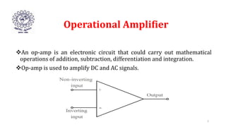
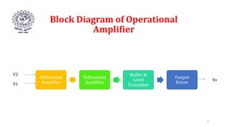
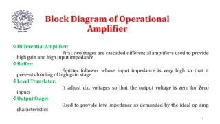
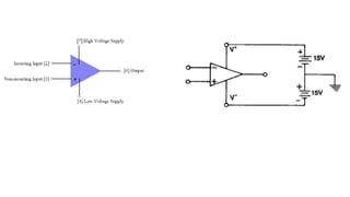
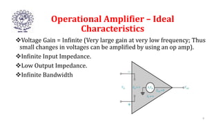
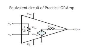
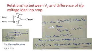
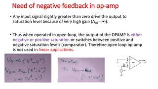
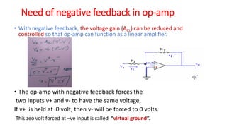
Operational Amplifier
IC 741
Operational Amplifier
An op-amp is an electronic circuit that could carry out mathematical
operations of addition, subtraction, differentiation and integration.
Op-amp is used to amplify DC and AC signals.
2
Block Diagram of Operational
Amplifier
Differential
Amplifier
Differential
Amplifier
Buffer &
Level
Translator
Output
Driver
3
V2
V1
Vo
Block Diagram of Operational
Amplifier
Differential Amplifier:
First two stages are cascaded differential amplifiers used to provide
high gain and high input impedance
Buffer:
Emitter follower whose input impedance is very high so that it
prevents loading of high gain stage
Level Translator:
It adjust d.c. voltages so that the output voltage is zero for Zero
inputs
Output Stage:
Used to provide low impedance as demanded by the ideal op amp
characteristics
4
Active component!
Introduction
Basic Symbol
Operational Amplifier – Ideal
Characteristics
Voltage Gain = Infinite (Very large gain at very low frequency; Thus
small changes in voltages can be amplified by using an op amp).
Infinite Input Impedance.
Low Output Impedance.
Infinite Bandwidth
8
Equivalent circuit of Practical OP.Amp
Ideal vs typical op amp
Ideal Op-Amp Typical Op-Amp
Input Resistance infinity 106  (bipolar)
109  - 1012  (FET)
Input Current 0 10-12 – 10-8 A
Output Resistance 0 100 – 1000 
Operational Gain infinity 105 - 109
Common Mode Gain 0 10-5
Bandwidth infinity Attenuates and phases at high
frequencies (depends on slew
rate)
Temperature independent Bandwidth and gain
Relationship between Vo and difference of i/p
voltage ideal op amp
V0 α difference of i/p voltage
V0 α (V+ - V-)
+Vsat
-Vsat
Open loop operation of Practical Op Amp
• Open loop gain high
• A ~= 106
• Small difference in the input
voltages result in a very large
output voltage
• Output limited by supply voltages
• Comparator
• If V+>V-, Vout = HVS (+15V)
• If V+<V-, Vout = LVS (-15V)
• If V+=V-, Vout = 0V
Limitations of Open Loop
Configuration in Operational
Amplifier
Distortion is introduced in the amplified output signal.
Open loop gain does not remains constant but varies with respect to
temperature and power supply.
Bandwidth of Op-amp is very small and almost equal to zero and it
makes it insufficient for practical use.
Applications:
Comparator
14
Need of negative feedback in op-amp
• Any input signal slightly greater than zero drive the output to
saturation level because of very high gain (AOL= ∞).
• Thus when operated in open-loop, the output of the OPAMP is either
negative or positive saturation or switches between positive and
negative saturation levels (comparator). Therefore open loop op-amp
is not used in linear applications.
Need of negative feedback in op-amp
• With negative feedback, the voltage gain (ACL) can be reduced and
controlled so that op-amp can function as a linear amplifier.
• The op-amp with negative feedback forces the
two Inputs v+ and v- to have the same voltage,
If v+ is held at 0 volt, then v- will be forced to 0 volts.
This zeo volt forced at –ve input is called “virtual ground”.
Basic Applications circuits
• Inverting op amp
• Non-inverting op amp
• Voltage follower

Introduction to Operational Amplifier.pptx

  • 1.
  • 2.
    Operational Amplifier An op-ampis an electronic circuit that could carry out mathematical operations of addition, subtraction, differentiation and integration. Op-amp is used to amplify DC and AC signals. 2
  • 3.
    Block Diagram ofOperational Amplifier Differential Amplifier Differential Amplifier Buffer & Level Translator Output Driver 3 V2 V1 Vo
  • 4.
    Block Diagram ofOperational Amplifier Differential Amplifier: First two stages are cascaded differential amplifiers used to provide high gain and high input impedance Buffer: Emitter follower whose input impedance is very high so that it prevents loading of high gain stage Level Translator: It adjust d.c. voltages so that the output voltage is zero for Zero inputs Output Stage: Used to provide low impedance as demanded by the ideal op amp characteristics 4
  • 6.
  • 8.
    Operational Amplifier –Ideal Characteristics Voltage Gain = Infinite (Very large gain at very low frequency; Thus small changes in voltages can be amplified by using an op amp). Infinite Input Impedance. Low Output Impedance. Infinite Bandwidth 8
  • 9.
    Equivalent circuit ofPractical OP.Amp
  • 10.
    Ideal vs typicalop amp Ideal Op-Amp Typical Op-Amp Input Resistance infinity 106  (bipolar) 109  - 1012  (FET) Input Current 0 10-12 – 10-8 A Output Resistance 0 100 – 1000  Operational Gain infinity 105 - 109 Common Mode Gain 0 10-5 Bandwidth infinity Attenuates and phases at high frequencies (depends on slew rate) Temperature independent Bandwidth and gain
  • 11.
    Relationship between Voand difference of i/p voltage ideal op amp V0 α difference of i/p voltage V0 α (V+ - V-)
  • 12.
  • 13.
    Open loop operationof Practical Op Amp • Open loop gain high • A ~= 106 • Small difference in the input voltages result in a very large output voltage • Output limited by supply voltages • Comparator • If V+>V-, Vout = HVS (+15V) • If V+<V-, Vout = LVS (-15V) • If V+=V-, Vout = 0V
  • 14.
    Limitations of OpenLoop Configuration in Operational Amplifier Distortion is introduced in the amplified output signal. Open loop gain does not remains constant but varies with respect to temperature and power supply. Bandwidth of Op-amp is very small and almost equal to zero and it makes it insufficient for practical use. Applications: Comparator 14
  • 15.
    Need of negativefeedback in op-amp • Any input signal slightly greater than zero drive the output to saturation level because of very high gain (AOL= ∞). • Thus when operated in open-loop, the output of the OPAMP is either negative or positive saturation or switches between positive and negative saturation levels (comparator). Therefore open loop op-amp is not used in linear applications.
  • 16.
    Need of negativefeedback in op-amp • With negative feedback, the voltage gain (ACL) can be reduced and controlled so that op-amp can function as a linear amplifier. • The op-amp with negative feedback forces the two Inputs v+ and v- to have the same voltage, If v+ is held at 0 volt, then v- will be forced to 0 volts. This zeo volt forced at –ve input is called “virtual ground”.
  • 17.
    Basic Applications circuits •Inverting op amp • Non-inverting op amp • Voltage follower